Table of Contents
Advertisement
Quick Links
Advertisement
Table of Contents

Related Manuals for Westermo MRD-405


Summary of Contents for Westermo MRD-405
- Page 1 MRD-405 Industrial 4G LTE Router...
- Page 2 6623-2212...
-
Page 3: General Information
Under no circumstances shall Westermo be responsible for any loss of data or income or any special, incidental, and consequential or indirect damages howsoever caused. -
Page 4: Safety And Regulations
Safety and Regulations Warning signs are provided to prevent personal injury and/or damages to the product. The following levels are used: Level of warning Description Consequence Consequence personal injury material damage Indicates a potentially Possible death or Major damage to the hazardous situation major injury product... -
Page 5: Before Installation
During installation, ensure a protective earthing conductor is first connected to the protective earthing terminal (only valid for metallic housings). Westermo recommends a cross-sectional area of at least 4 mm2. Upon removal of the product, ensure that the protective earthing conductor is disconnected last. - Page 6 RADIO PRODUCTS Observe the usage limitations of radio products at filling stations, in chemical plants, in systems with explosives or potentially explosive locations. The product may not be used in airplanes. Exercise particular caution near personal medical aids, such as pacemakers and hearing aids.
-
Page 7: Care Recommendations
If the product is used in a manner not according to specification, the protection provided by the equipment may be impaired. If the product is not working properly, contact the place of purchase, nearest Westermo distributor office or Westermo technical support. -
Page 8: Simplified Eu Declaration Of Conformity
Simplified EU Declaration of Conformity Hereby, Westermo declares that the equipment is in compliance with applicable EU directives. The full EU declaration of conformity and other detailed information are available at the respective product page at www.westermo.com. Agency Approvals and Standards Compliance... -
Page 9: Type Tests And Environmental Conditions
Type Tests and Environmental Conditions Phenomena Test Description Test levels EN 61000-4-2 Enclosure contact ± 6 kV (crit A)* Enclosure air ± 8 kV (crit A)* RF field AM modulated IEC 61000-4-3 Enclosure 10 V/m (crit A)* (80 – 2700 MHz) Fast transient EN 61000-4-4 Signal ports... -
Page 10: Available Models
Devices connected to the Internet require countermeasures towards cyber threats. The MRD-405 offers protection of transmissions from malicious eavesdroppers via encrypted communication tunnels (VPN), and features a simple, yet powerful, packet inspection firewall. -
Page 11: Interface Specifications
Interface Specifications Power Rated voltage 12 – 24 VDC Operating voltage 10 – 36 VDC Start-up current (max) 400 mA Rated frequency Consumption guidance* Voltage Mode Consumption 24 VDC Not registered 44 mA 1.056 W 24 VDC GSM and UMTS registered 50 mA 1.2 W 24 VDC... - Page 12 Electrical specification 3 volts SIM supported Number of slots Cellular Technologies Technology MRD-405 MRD-405-AU Frequency (MHz) Frequency (MHz) 900/1800 850/900/1800/1900 B1 (2100), B5 (850), B8 (900) B1 (2100), B2 (1900), B5 (850), B8 (900) B1 (2100), B3 (1800), B5 (850),...
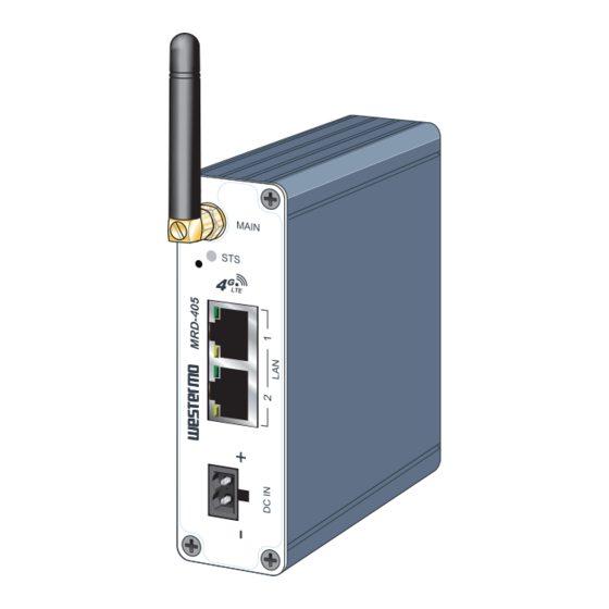
- Page 13 Connections SIM card reader Ethernet TX connections Antenna (RJ-45 connector) LAN1-2 MAIN Position Direction Description Led indicators In/Out Factory default reset switch In/Out TD– In/Out – Not Connected – Not Connected In/Out RD– – Not Connected – Not Connected Power connector Protective earth...
-
Page 14: Led Indicators
LED Indicators State Status Description Startup/POST NOT LIT Power issue No wireless network has been detected Running/Normal RED FLASH A wireless network has been detected GREEN Power up self test OK/no issues Connected GREEN 1 BLINK Signal strength indication: GREEN 2 BLINK 1 - Very poor GREEN 3 BLINK 2 - Normal... - Page 15 Protocols and Functionality Ethernet Technologies IEEE 802.3 for 10BaseT IEEE 802.3u for 100BaseTX Layer-2 QoS IEEE 802.1p Class of Service Positioning (GNSS) Passive and Active antenna GPS/GLONASS/BeiDou/Galileo/QZSS IP Routing, Static IP routing Firewall, Stateful inspection Firewall/ACL, NAT, Port Forwarding 1 x IPsec VPN, PSK & X.509, Fail-over and Cyber Security 1 x OpenVPN/SSL VPN client Simple Certificate Enrollment Protocol (SCEP)
-
Page 16: Getting Started
Getting Started Installing the SIM Card … Insert the SIM card into the SIM card reader with the contacts facing up. SIM card reader Note: Before removing or inserting the SIM card, ensure that the power has been turned off and the power connector has been removed from the MRD. -
Page 17: Windows Pc Network Settings
Configuration Accessing and Using the Web Interface All configuration of the MRD can be done via the web interface. In order to view the web pages a computer with a fixed IP address, on the same sub-net as the MRD, will need to be connected to one of the LAN ports. - Page 18 Figure 1 7. The Internet Protocol (TCP/IP)Properties dialog box, change the settings to match those shown in Figure 2, and then click ”OK. Figure 2 Note: If a web browser was open prior to making the network changes, then it will need to be closed and re-started before attempting to connect to the MRD.
- Page 19 IP address settings of the PC. Enter the following login details: • User Name: admin • Password: westermo • The Status summary page will be displayed, it will be similar to Figure 3. Figure 3 Note: If the unit is not yet configured it is likely that the Network Status and Connection Status will indicate a fault condition.
- Page 20 Basic Configuration The three sections below detail the steps needed to configure the MRD for basic packet mode functionality. For details on how to configure the unit for Circuit Switched mode and for more advanced configuration refer to the Advanced Configuration section of the Reference Guide.
- Page 21 Adding a Network Connection Profile To access the wireless packet mode settings click on the ”Packet mode'' tab. The screen shown in Figure 6 will be displayed. The page shows the connection configuration details and is divided into two sections. The first section shows the current connection state for the selected profile.
- Page 22 Figure 7 Enter APN Set Authentication Enter username Enter password Click ”Update” to save profile Note: In order to set a password click the check-box marked New. The password can now be entered in the text field. The password is visible as it is being typed so that it can be checked for errors prior to being set.
-
Page 23: Enable The Wireless Connection
Enable the Wireless Connection To complete the configuration of the wireless connection, set the ”Connection state” to ”Always connect” and click the ”Update” button to save the changes. Once the changes have been set, the MRD will initiate a connection. Normally it will take up to 30 seconds to esablish a connection. -
Page 24: Setting The Ip Address
Configure the LAN Interface and DHCP Server To access the configuration page for the LAN interface and DHCP Server, select ”Interfaces” from the top level menu. A LAN interface screen similar to the one shown in Figure 10 will be displayed. Figure 10 Setting the IP Address If it is desired to change the IP address of the LAN port, follow the steps below:... - Page 25 Under the ”DHCP Server Configuration table”: • Check the ”Enabled box”. • Enter the first address of the group in the ”Start Address box”. • Enter the last address of the group in the ”End Address box”. • Enter a lease time for the ”Default Lease time”. •...
-
Page 26: Earth Connection
Mounting The MRD-405 should be mounted on 35 mm DIN-rail, which is horizontally mounted inside an apparatus cabinet or similar. Snap on mounting, see figure. Mount the MRD-405 with the integrated DIN-clip: Earth connection For correct function, the ground connection on the unit needs to be properly connected to a solid ground. - Page 27 Dimensions Measurements are stated in millimeters. 6623-2212...
- Page 28 Westermo • Metallverksgatan 6, SE-721 30 Västerås, Sweden Tel +46 16 42 80 00 Fax +46 16 42 80 01 E-mail: info@westermo.com www.westermo.com REV. D 6623-2212 2022-12 Westermo Network Technologies AB...
Need help?
Do you have a question about the MRD-405 and is the answer not in the manual?
Questions and answers