
Related Manuals for Westermo Viper-12 Series


Summary of Contents for Westermo Viper-12 Series
- Page 1 User Guide 6641-2242 Viper-12 S E R I E S SRV 1 SRV 2 X1 2 RST P FRN T CO N X1 2 12-port Ethernet M12 switch / GigE www.westermo.com...
-
Page 2: Software Tools
Under no circumstances shall Westermo be responsible for any loss of data or income or any special, incidental, and consequential or indirect damages howsoever caused. -
Page 3: Before Installation
Safety Before installation: Read this manual completely and gather all information on the unit. Make sure that you understand it fully. Check that your application does not exceed the safe operating specifications for this unit. This unit should only be installed by qualified personnel. This unit should be built-in to an apparatus cabinet, or similar, where access is restricted to service personnel only. -
Page 4: Care Recommendations
… Do not cover or bring mechanical force to the ventilation membrane on the back of the unit. If the unit is not working properly, contact the place of purchase, nearest Westermo distributor office or Westermo Tech support. Maintenance No maintenance is required, as long as the unit is used as intended within the specified conditions. -
Page 5: Agency Approvals And Standards Compliance
Agency approvals and standards compliance Type Approval / Compliance EN 61000-6-1, Immunity residential environments EN 61000-6-2, Immunity industrialokokvironments EN 61000-6-3, Emission residential environments EN 61000-6-4, Emission industrial environments EN 50121-3-2, Railway applications – Rolling stock – apparatus EN 50121-4/IEC 62236-4, Railway signaling and telecommunications apparatus FCC Part 15 Class B Safety EN 60950-1, IT equipment... -
Page 6: Declaration Of Conformity
Declaration of Conformity Westermo Teleindustri AB Declaration of conformity The manufacturer Westermo Teleindustri AB SE-640 40 Stora Sundby, Sweden Herewith declares that the product(s) Type of product Model Art no 12-port unmanaged Ethernet M12 Switch Viper-012 3641-0540 12-port managed Ethernet M12 Switch... - Page 7 Declaration of Conformity Westermo Teleindustri AB Declaration of conformity The manufacturer Westermo Teleindustri AB SE-640 40 Stora Sundby, Sweden Herewith declares that the product(s) Type of product Model Art no 12-port managed Gig Ethernet M12 Switch Viper-112-T3G, -212-T3G 3641-0530, -0550 is in conformity with the following EC directive(s).
-
Page 8: Type Tests And Environmental Conditions
Type tests and environmental conditions Environmental phenomena Basic standard Description Test levels EN 61000-4-2 Enclosure Contact: ±6 kV Air: ±8 kV Fast transients EN 61000-4-4 Power port ±5 kV Signal ports ±2 kV Earth port ±1 kV Surge EN 61000-4-5 Power port L-E: ±2 kV, 12Ω, 9 μF, 1.2/50 μs L-L: ±1 kV, 2Ω, 18 μF, 1.2/50 μs... - Page 9 Description Designed for harsh industrial environments The Viper-12 series is a series of managed and unmanaged rugged Ethernet switches designed for applications with severe operating conditions and extreme environments. With an ultra robust design, sealed to IP67 and vibration resistant to and exceeding...
-
Page 10: Interface Specifications
Viper-x12-T3G: X1-X3, X5-X7, X9-X11: 1500 VAC rms to other ports X4, X8, X12: 500 VAC rms to other ports Connection 4-pin M12 D-code, auto MDI/MDI-X, use e g Westermo cable 3146-1100 M12-M12 – 1 m 3146-1101 M12-M12 – 5 m 3146-1103 RJ45-M12 – 1 m 3146-1104 RJ45-M12 –... - Page 11 Circuit type SELV Isolation to Ethernet ports, 1500 VAC rms DC, 1500 VAC rms No isolation to CON Connection 5-pin M12 female A-code, use Westermo USB plug 3641-0190 CON, Console port Electrical specification RS-232 Data rate 115.2 kbit/s Data format...
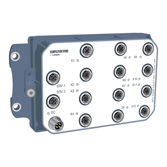
- Page 12 Location of interface ports and LED’s, Viper-012/112/212 Ethernet connection TX LED indicators (for details see page 15) connection Console connection RSTP FRNT Power connection Earth connection 6641-2242...
- Page 13 Viper-112/212 Managed Viper-012 Unmanaged SRV 1 RSTP FRNT SRV 2 SRV 1 & SRV 2 only for internal use by Westermo staff Power Pin number Signal No 1 +DC1 No 2 +DC2 No 3 -COM No 4 -COM Pin number...
- Page 14 Location of interface ports and LED’s, Viper-112/212-T3G Ethernet connection TX LED indicators (for details see page 15) connection Console connection Power connection GigE Earth connection 6641-2242...
- Page 15 Viper-112-T3G / Viper-212-T3G Ethernet connection Pin number Signal No 1 No 2 No 3 TX– No 4 RD– Housing Shield Power connection Pin number Signal No 1 +DC1 No 2 +DC2 No 3 -COM No 4 -COM Viper-x12-T3G supports redundant power connection. The positive inputs are +DC1 and +DC2, the negative input for both supplies are –COM.
- Page 16 The USB port can be used to copy configuration and log files to/from the switch. The following steps needs to be taken 1. Connect the USB plug (use Westermo USB plug 3641-0190) to the USB port. 2. Access the switch CLI (via console cable or SSH) 3.
-
Page 17: Led Indicators
LED Indicators Status Description Unit has no power. GREEN All OK, no alarm condition. Alarm condition, or until unit has started up. (Alarm conditions are configurable, see ''WeOS RSTP Management Guide''). FRNT BLINK Location indicator ("Here I am!"). Activated when connected to IPConfig Tool, or when configuring the unit via Web or CLI. -
Page 18: Wall Mounting
Wall mounting There are four 6 mm bore holes intended for mounting the unit. The unit can be mounted vertical or horizontal. Use four M5 screws with 12 mm washer on a flat and stable surface. RSTP FRNT Connection of cables Recommended tightening torque for the M12 connectors: 0.6 Nm Note that unused connectors must be covered by a protective cap (delivered with the unit), tightened to the specified torque, in order to fulfill the specified ingress protection... -
Page 19: Getting Started
This product runs Westermo Operating System (WeOS) which provides several management tools that can be used for configuration of the unit. • IPConfig tool This is a custom Westermo tool used for discovery of attached Westermo units. • Web Configuration of the unit using the web browser. -
Page 20: Referring Documents
Referring documents Type Description Document number Management Guide Westermo OS management guide 6101-3201 Factory default It is possible to set the unit to factory default settings by using two standard Ethernet M12 cables. 1. Power off the switch and disconnect all Ethernet cables. - Page 21 Dimensions Measurements are stated in millimeters. Description Date Designer Approved Created 130225 PaPu ToDu 174 ±1 164 ±1 65,4 ±1 11 ±1 142 ±1 54,1 ±1 73,5 48,8 23,3 6,7 ±1 6,5 - 0,5(4x) Pos No Quantity Description Designation / Dimension Material / Remark Designer Approved...
-
Page 22: Sales Units
Other Offices infos@westermo.fr sales@westermo.com.sg www.westermo.fr www.westermo.com Germany Sweden info@westermo.de info.sverige@westermo.se www.westermo.de www.westermo.se For complete contact information, please visit our website at www.westermo.com/contact or scan the QR code REV. D 6641-2242 2015-11 Westermo Teleindustri AB, Sweden – A Beijer Electronics Group Company...
Need help?
Do you have a question about the Viper-12 Series and is the answer not in the manual?
Questions and answers