
Related Manuals for Westermo MDI-118 Series


Summary of Contents for Westermo MDI-118 Series
- Page 1 MDI-118 Series MDI-112 Series User’s Manual Version 1.1 Industrial Managed Ethernet Switch...
-
Page 2: Copyright Notice
Copyright Notice Copyright 2013 Westermo Teleindustri AB All rights reserved. Reproduction in any form or by any means without permission is prohibited. - Page 3 Federal Communications Commission (FCC) Statement This equipment has been tested and found to comply with the limits for a Class A digital device, pursuant to Part 15 of the FCC Rules. These limits are designed to provide reasonable protection against harmful interference when the equipment is operated in a commercial environment.
- Page 4 Index Introduction ......................2 Overview ....................2 Major Features ................... 2 Package List ....................3 Hardware Installation .....................4 Hardware Introduction ................4 Wiring Power Inputs .................. 6 Wiring Digital Output ................. 7 Wiring Earth Ground .................. 8 Wiring Fast Ethernet Ports ................. 8 Wiring Fiber Ports ..................
- Page 5 4.15 Logout ....................152 Appendix ......................153 Pin Assignment of the RS-232 Console Cable ........153 Private MIB ..................... 154 ModBus TCP /IP ..................155 Revision History..................170...
-
Page 6: Introduction
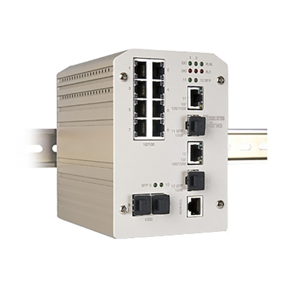
1 Introduction Welcome to Westermo i-line MDI-118/MDI-112 Series User Manual. Following topics are covered in this chapter: Overview Major Features Package Checklist Overview The MDI-118-F2G is equipped with 16 10/100TX Fast Ethernet ports and 2 1000Base-T/Gigabit SFP combo ports. The MDI-112-F4G is equipped with 8 10/100TX Fast Ethernet ports, 2 Gigabit SFP and 2 1000Base-T/Gigabit SFP Combo ports. -
Page 7: Package List
Jumbo Frame up to 9,216 byte RSTP/STP, 256 802.1Q VLAN, QoS and up to 6/8 trunk groups IGMP Snooping, GMRP Rate Control for multicast message management LLDP for network topology live update SNMP V1/V2c/V3, RMON for remote management ... -
Page 8: Hardware Installation
2 Hardware Installation This chapter includes hardware introduction, installation and configuration information. Following topics are covered in this chapter: Hardware Introduction Dimension Panel Layout Bottom View Wiring Power Inputs Wiring Digital Input Wiring Relay Output Wiring Ethernet Ports Wiring Combo Ports Wiring RS-232 console cable DIN-Rail Mounting Installation Wall-Mounting Installation... - Page 9 Figure of MDI-118-F2G Figure of MDI-112-F4G...
-
Page 10: Wiring Power Inputs
Wiring Power Inputs DC Power Input Follow below steps to wire the redundant DC power inputs. Insert positive and negative wires into V+ and V- contacts respectively of the terminal block connector Tighten the wire-clamp screws to prevent DC wires from being loosened. Power 1 and Power 2 support power redundancy and polarity reverse protection functions. -
Page 11: Wiring Digital Output
Wiring Digital Output The switch provides two digital outputs, also known as Relay Output. The relay contacts are energized (open) for normal operation and will close for fault conditions. The fault conditions include power failure, Ethernet port link break or other pre-defined events which can be configured in management UI. -
Page 12: Wiring Earth Ground
Wiring Earth Ground To ensure the system will not be damaged by noise or any electrical shock, we suggest you to make exact connection with switch with Earth Ground. For DC input, loosen the earth ground screw using a screw driver; then tighten the screw after earth ground wire is connected. -
Page 13: Wiring Fiber Ports
10Base-T: 2-pair UTP/STP Cat. 3, 4, 5 cable, EIA/TIA-568 100-ohm (100m) 100 Base-TX: 2-pair UTP/STP Cat. 5 cable, EIA/TIA-568 100-ohm (100m) 1000 Base-TX: 4-pair UTP/STP Cat. 5 cable, EIA/TIA-568 100-ohm (100m) Wiring Fiber Ports Small Form-factor Pluggable (SFP) The SFP ports fulfill the SFP standard. To ensure the system reliability, it is recommended to use the approved Gigabit SFP Transceiver. -
Page 14: Din-Rail Mounting Installation
DIN-Rail Mounting Installation The DIN-Rail clip is already attached to the Switch when packaged. If the DIN-Rail clip is not screwed on the Switch, follow the instructions and the figure below to attach the DIN-Rail clip to the switch. 1. Use the screws to attach DIN-Rail clip to the real panel 2. - Page 15 Lightly push the bottom of DIN-Rail clip into the track. Check if the DIN-Rail clip is tightly attached to the track. To remove the switch from the track, reverse the steps above.
-
Page 16: Wall Mounting Installation
2.10 Wall Mounting Installation Follow the steps below to install the switch with the wall mounting plate. 1. To remove the DIN-Rail clip from the switch, loosen the screws. 2. Place the wall mounting plate on the rear panel of the switch. 3. -
Page 17: Safety Warning
2.11 Safety Warning The Equipment intended for installation in a Restricted Access Location. The warning test is provided in user manual. Below is the information: ”For tilslutning af de ovrige ledere, se medfolgende installationsvejledning”. “Laite on liitettava suojamaadoitus-koskettimilla varustettuun pistorasiaan” „Apparatet ma tilkoples jordet stikkontakt“... -
Page 18: Preparation For Management
Console port of the switch. If you lose/lost the cable, please follow the console cable PIN assignment to find a new one or contact your closest Westermo sales office. (Refer to the appendix). Go to Start -> Program -> Accessories -> Communication -> Hyper Terminal Give a name to the new console connection. -
Page 19: Preparation For Web Interface
Type http://192.168.2.200 (or the IP address of the switch). And then press Enter. The login screen will appear next. Type in the user name and the password. Default user name is admin and password westermo. 10. Select Language type: English and Simplified Chinese. - Page 20 Click on Enter or OK. The Welcome page of the web-based management interface will then appear. Once you enter the web-based management interface, you can freely change the IP address to fit your network environment. Note 1: Internet Explorer 5.0 or later versions do not allow Java applets to open sockets by default.
-
Page 21: Preparation For Telnet Console
The login screen will appear next. Key in the user name and the password. The default user name is admin and password is westermo. Press Enter or click on OK. The welcome page of the web-based management interface will then appear. - Page 22 3.3.2 SSH (Secure Shell) The switch also support SSH console. You can remotely connect to the switch by command line interface. The SSH connection can secure all the configuration commands you send to the switch. When you wish to establish a SSH connection with the switch, you should download the SSH client tool first.
- Page 23 3. After few seconds, the SSH connection is opened. 4. Type the Login Name and its Password. The default Login Name and Password are admin / westermo. 5. All the commands you see in SSH are the same as the CLI commands you see via RS-232 console.
-
Page 24: Feature Configuration
4 Feature Configuration This chapter explains how to configure the software features. There are four ways to access the switch: Serial console, Telnet/SSH, Web browser and SNMP. Following topics are covered in this chapter: Command Line Interface (CLI) Introduction Basic Setting Port Configuration Network Redundancy VLAN... -
Page 25: Command Line Interface Introduction
Command Line Interface Introduction The Command Line Interface (CLI) is one of the user interfaces to the switch’s embedded software system. You can view the system information, show the status, configure the switch and receive a response back from the system by typing in a command. - Page 26 Global Configuration Mode: Type configure terminal in privileged EXEC mode you will then enter global configuration mode. In global configuration mode, you can configure all the features that the system provides you. Type interface IFNAME/VLAN to enter interface configuration mode, exit to leave.
- Page 27 Available command lists of the global configuration mode. Switch(config)# interface fa1 Switch(config-if)# acceptable Configure 802.1Q acceptable frame types of a port. auto-negotiation Enable auto-negotiation state of a given port description Interface specific description duplex Specify duplex mode of operation for a port End current mode and change to enable mode exit Exit current mode and down to previous mode...
- Page 28 Summary of the 5 command modes. Command Main Function Enter and Exit Method Prompt Mode User EXEC This is the first level of access. Enter: Login successfully Switch> User can ping, telnet remote Exit: exit to logout. device, and show some basic Next mode: Type enable to information enter privileged EXEC mode.
- Page 29 Here are some useful commands to see available commands. It can save time when typing and avoid errors. ? To see all the available commands in this mode. It helps you to see the next command you can/should type as well. Switch(config)# interface (?) IFNAME Interface's name vlan...
-
Page 30: Basic Setting
Basic Setting The Basic Setting group provides you to configure switch information, IP address and user name/password of the system. It also allows you to do firmware upgrade, backup and restore configuration, reload factory default, and reboot the system. Following commands are included in this section: 4.2.1 Switch Setting 4.2.2 Admin Password 4.2.3 IP Configuration... - Page 31 User name: You can type in a new user name here. The default setting is admin. Password: You can type in a new password here. The default setting is westermo. Confirm Password: You need to type the new password again to confirm it.
- Page 32 Figure 4.2.2.2 Popup alert window for Incorrect username. 4.2.3 IP Configuration This function allows users to configure the switch’s IP address settings. DHCP Client: You can select to Enable or Disable DHCP Client function. When DHCP Client function is enabled, an IP address will be assigned to the switch from the network’s DHCP server.
- Page 33 IPv6 Configuration –An IPv6 address is represented as eight groups of four hexadecimal digits, each group representing 16 bits (two octets). The groups are separated by colons (:), and the length of IPv6 address is 128bits. An example of an IPv6 address is: 2001:0db8:85a3:0000:0000:8a2e:0370:7334. The default IP address of the Managed Switch is fe80:0:0:0:212:77ff:fe60:ce8c, and the Leading zeroes in a group may be omitted.
- Page 34 4.2.4 Time Setting Time Setting source allow user to set the time manually or via a NTP server. Network Time Protocol (NTP) is used to synchronize computer clocks in the network. You can configure NTP settings here to synchronize the clocks of several switches on the network.
- Page 35 Switch(config)# clock timezone 01 (GMT-12:00) Eniwetok, Kwajalein 02 (GMT-11:00) Midway Island, Samoa 03 (GMT-10:00) Hawaii 04 (GMT-09:00) Alaska 05 (GMT-08:00) Pacific Time (US & Canada) , Tijuana 06 (GMT-07:00) Arizona 07 (GMT-07:00) Mountain Time (US & Canada) 08 (GMT-06:00) Central America 09 (GMT-06:00) Central Time (US &...
- Page 36 38 (GMT+03:00) Baghdad 39 (GMT+03:00) Kuwait, Riyadh 40 (GMT+03:00) Moscow, St. Petersburg, Volgograd 41 (GMT+03:00) Nairobi 42 (GMT+03:30) Tehran 43 (GMT+04:00) Abu Dhabi, Muscat 44 (GMT+04:00) Baku, Tbilisi, Yerevan 45 (GMT+04:30) Kabul 46 (GMT+05:00) Ekaterinburg 47 (GMT+05:00) Islamabad, Karachi, Tashkent 48 (GMT+05:30) Calcutta, Chennai, Mumbai, New Delhi 49 (GMT+05:45) Kathmandu 50 (GMT+06:00) Almaty, Novosibirsk...
- Page 37 Daylight Saving Time: Set when Enable Daylight Saving Time start and end, during the Daylight Saving Time, the device’s time is one hour earlier than the actual time. Daylight Saving Start and Daylight Saving End: the functions allows user to selects and apply the daylight saving start and end week by monthly basis.
- Page 38 4.2.6 DHCP Server You can select to Enable or Disable DHCP Server function. It will assign a new IP address to link partners, and also supports DHCP server option 82 with forwarding policy, and provides port-based DHCP server with IP address binding feature.
- Page 39 removing function. You can type in the specified IP and MAC address, then click Add to add a new MAC&IP address binding rule for a specified link partner, like PLC or any device without DHCP client function. To remove from the binding list, just select the rule to remove and click Remove.
- Page 40 DHCP Leased Entries: the switch provides an assigned IP address list for user check. It will show the MAC and IP address that was assigned by the switch. Click the Reload button to refresh the listing. DHCP Relay Agent You can select to Enable or Disable DHCP relay agent function, and then select the modification type of option 82 field, circuit ID, remote ID.
- Page 41 Relay policy drop: Drops the option 82 field and do not add any option 82 field. Relay policy keep: Keeps the original option 82 field and forwards to server. Relay policy replace: Replaces the existing option 82 field and adds new option 82 field.
- Page 42 the configuration back to the switch. This mode is only provided by Web UI while CLI is not supported. TFTP Server mode: In this mode, the switch acts as TFTP client. Before you do so, make sure that your TFTP server is ready. Then please type the IP address of TFTP Server and Backup configuration file name.
- Page 43 Note: point to the wrong file will cause the entire configuration missed. 4.2.8 Firmware Upgrade In this section, you can update the latest firmware for your switch. Westermo provides the latest firmware in the web site. The new firmware may include new features, bug fixes or other software changes.
- Page 44 There are 2 modes for users to backup/restore the configuration file, Local File mode and TFTP Server mode. Local File mode: In this mode, the switch acts as the file server. Users can browse the target folder and then type the file name to backup the configuration. Users also can browse the target folder and select the existed configuration file to restore the configuration back to the switch.
- Page 45 Popup message screen to show you that have done the command. Click on OK to close the screen. Then please go to Reboot page to reboot the switch. Click on OK. The system will then auto reboot the device. Note: If you already configured the IP of your device to other IP address, when you use this command by CLI and Web UI, our software will not reset the IP address to default IP.
- Page 46 Switch(config)# hostname WORD Network name of this system Switch(config)# hostname SWITCH SWITCH(config)# System Location SWITCH(config)# snmp-server location Sweden System Contact SWITCH(config)# snmp-server contact support@westermo.se Display SWITCH# show snmp-server name SWITCH SWITCH# show snmp-server location Sweden SWITCH# show snmp-server contact support@westermo.se SWITCH>...
- Page 47 Display SWITCH# show administrator Administrator account information name: super password: super IP Configuration IP Address/Mask SWITCH(config)# int vlan 1 (192.168.2.8, SWITCH(config-if)# ip 255.255.255.0 address dhcp SWITCH(config-if)# ip address 192.168.2.8/24 SWITCH(config-if)# ip dhcp client SWITCH(config-if)# ip dhcp client renew Gateway SWITCH(config)# ip route 0.0.0.0/0 192.168.2.254/24 Remove Gateway SWITCH(config)# no ip route 0.0.0.0/0 192.168.2.254/24 Display...
- Page 48 select. IEEE 1588 Switch(config)# ptpd run <cr> preferred-clock Preferred Clock slave Run as slave Display SWITCH# sh ntp associations Network time protocol Status : Disabled Primary peer : N/A Secondary peer : N/A SWITCH# show clock Sun Jan 1 04:14:19 2006 (GMT) Greenwich Mean Time: Dublin, Edinburgh, Lisbon, London SWITCH# show clock timezone clock timezone (26) (GMT) Greenwich Mean Time: Dublin,...
- Page 49 Switch(config-dhcp)#default-router 192.168.17.254 Lease time configure Switch(config-dhcp)#lease 300 (300 sec) DHCP Relay Agent Enable DHCP Relay Agent Switch# Switch# configure terminal Switch(config)# router dhcp Switch(config-dhcp)# service dhcp Switch(config-dhcp)# ip dhcp relay information option Enable DHCP Relay policy Switch(config-dhcp)# ip dhcp relay information policy replace drop Relay Policy...
- Page 50 Note 1: To backup the latest startup configuration file, you should save current settings to flash first. You can refer to 4.12 to see how to save settings to the flash. Note 2: 192.168.2.33 is the TFTP server’s IP and default.conf is name of the configuration file.
-
Page 51: Port Configuration
Port Configuration Port Configuration group enables you to enable/disable port state, or configure port auto-negotiation, speed, and duplex, flow control, rate limit control and port aggregation settings. It also allows you to view port status and aggregation information. Following commands are included in this section: 4.3.1 Port Control 4.3.2... - Page 52 Duplex(10 Half), 100M Full Duplex(100 Full) and 100M Half Duplex(100 Half). Gigabit Ethernet Port: AutoNegotiation, 10M Full Duplex(10 Full), 10M Half Duplex(10 Half), 100M Full Duplex(100 Full), 100M Half Duplex(100 Half), 1000M Full Duplex(1000 Full), 1000M Half Duplex(1000 Half). The default mode is Auto Negotiation mode. In Flow Control column, “Symmetric”...
- Page 53 Unknown info, it may mean that the vendor doesn’t provide their information or that the information of their transceiver can’t be read. 2. if the plugged DDM SFP transceiver is not certified by Westermo, the DDM function will not be supported. But the communication will not be disabled.
- Page 54 the volume in the blank. The volume of the switch is step by 8Kbps. 4.3.4 Storm Control The Storm Control is similar to Rate Control. Rate Control filters all the traffic over the threshold you configure in the User Interface. Storm Control allows user to define the Rate for specific Packet Types.
- Page 55 Packet type: You can assign the Rate for specific packet types based on packet number per second. The packet types of the Ingress Rule listed here include Broadcast, DLF (Destination Lookup Failure) and Multicast. Choose Enable/Disable to enable or disable the storm control for a specific port. Rate: This column allows you to manually assign the limit rate of the port.
- Page 56 Aggregation Setting Trunk Size: The switch can support up to 8 trunk groups. Each trunk group can support up to 8 member ports. Since the member ports should use same speed/duplex, the maximum trunk size is decided by the port volume. Group ID: Group ID is the ID for the port trunking group.
- Page 57 Group ID: Display Trunk id set up in Aggregation Setting. Type: Static or LACP set up in Aggregation Setting. Aggregated: When the LACP links is up, you can see the member ports in Aggregated column. Individual: When LACP is enabled, member ports of LACP group which are not connected to correct LACP member ports will be displayed in the Individual column.
- Page 58 Switch(config)# interface gigabitethernet10 eject port 10 SFP DDM transceiver. Switch(config-if)# sfp ddm eject DDM SFP on Port 10 normally ejected. Port Control – Switch(config)# interface fa1 Auto Switch(config-if)# auto-negotiation Negotiation Auto-negotiation of port 1 is enabled! Port Control – Switch(config-if)# speed 100 Force Port1 Link Change to DOWN...
- Page 59 Mdix mode is Disable. Medium mode is Copper. Switch# show sfp ddm show SFP DDM information Port 8 Temperature:N/A Tx power:N/A Rx power:N/A Port 9 Temperature:64.00 C <range :0.0-80.00> Tx power:-6.0 dBm <range : -9.0 - -4.0> Rx power:-30.0 dBm <range: -30.0 - -4.0> Port 10 Temperature:67.00 C <range :0.0-80.00>...
- Page 60 Bandwidth <0-100> Limit in magabits per second (0 is no limit) Switch(config-if)# rate-limit ingress bandwidth 8 Set the ingress rate limit 8Mbps for Port 1.
- Page 61 Storm Control Strom Switch(config-if)# storm-control Control – broadcast Broadcast packets Packet Type Destination Lookup Failure multicast Multicast packets Storm Control Switch(config-if)# storm-control broadcast - Rate <0-262143> Rate limit value 0~262143 packet/sec Switch(config-if)# storm-control broadcast 10000 Enables rate limit for Broadcast packets for Port 13. Switch(config-if)# storm-control multicast 10000 Enables rate limit for Multicast packets for Port 13.
- Page 62 Display - Switch# show trunk group 1 Trunk FLAGS: I -> Individual P -> In channel D -> Port Down Trunk Group GroupID Protocol Ports --------+---------+------------------------------------ LACP 8(D) 9(D) 10(D) Switch# show trunk group 2 FLAGS: I -> Individual P -> In channel D ->...
-
Page 63: Network Redundancy
Network Redundancy The switch firmware supports standard RSTP, MSTP, Multiple Super Ring, Rapid Dual Homing. Multiple Spanning Tree Protocol(MSTP) is a direct extension of RSTP. It can provide an independent spanning tree for different VLANs. It simplifies network management, provides for even faster convergence than RSTP by limiting the size of each region, and prevents VLAN members from being segmented from the rest of the group (as sometimes occurs with IEEE 802.1D STP). - Page 64 RSTP RSTP is the abbreviation of Rapid Spanning Tree Protocol. If a switch has more than one path to a destination, it will lead to message loops that can generate broadcast storms and quickly bog down a network. The spanning tree was created to combat the negative effects of message loops in switched networks.
- Page 65 Note: The Web GUI allows user select the priority number directly. This is the convenience of the GUI design. When you configure the value through the CLI or SNMP, you may need to type the value directly. Please follow the n x 4096 rules for the Bridge Priority.
- Page 66 Port Configuration Select the port you want to configure and you will be able to view current settings and status of the port. Path Cost: Enter a number between 1 and 200,000,000. This value represents the “cost” of the path to the other bridge from the transmitting bridge at the specified port.
- Page 67 4.4.3 STP Information This page allows you to see the information of the root switch and port status. Root Information: You can see root Bridge ID, Root Priority, Root Port, Root Path Cost and the Max Age, Hello Time and Forward Delay of BPDU sent from the root switch.
- Page 68 with IEEE 802.1D STP). While using MSTP, there are some new concepts of network architecture. A switch may belong to different groups, act as root or designate switch, generate BPDU for the network to maintain the forwarding table of the spanning tree. With MSTP can also provide multiple forwarding paths and enable load balancing.
- Page 69 To configure the MSTP setting, the STP Mode of the STP Configuration page should be changed to MSTP mode first. After enabled MSTP mode, then you can go to the MSTP Configuration pages. MSTP Region Configuration This page allows configure the Region Name and its Revision, mapping the VLAN to Instance and check current MST Instance configuration.
- Page 70 Once you finish your configuration, click on Apply to apply your settings. New MST Instance This page allows mapping the VLAN to Instance and assign priority to the instance. Before mapping VLAN to Instance, you should create VLAN and assign the member ports first.
- Page 71 4.4.5 MSTP Port Configuration This page allows configure the Port settings. Choose the Instance ID you want to configure. The MSTP enabled and linked up ports within the instance will be listed in this table. Note that the ports not belonged to the Instance, or the ports not MSTP activated will not display.
- Page 72 in blocking state and turn to forwarding state in 4 seconds. Once you finish your configuration, click on Apply to save your settings. 4.4.6 MSTP Information This page allows you to see the current MSTP information. Choose the Instance ID first. If the instance is not added, the information remains blank.
- Page 73 to connect with a core managed switch easily and conveniently. With RDH technology, you can also couple several Rapid Super Rings or RSTP cloud together, which is also known as Auto Ring Coupling. TrunkRing technology allows integrate MSR with LACP/Port Trunking. The LACP/Trunk aggregated ports is a virtual interface and it can work as the Ring port of the MSR.
- Page 74 all of the switches have the same priority, the switch with the highest MAC address will be selected as Ring Master. Ring Port1: In Rapid Super Ring environment, you should have two Ring Ports. No matter if the switch is Ring Master or not, when configuring RSR, two ports should be selected as Ring Ports.
- Page 75 ID: Ring ID. Version: which version of this ring, this field could be Rapid Super Ring, Super Ring. Role: This Switch is RM or nonRM Status: If this field is Normal which means the redundancy is activated. If any one of the links in the Ring is down, then the status will be Abnormal.
- Page 76 1-65535, 32-bit based value range from 1-200,000,000 Switch(config-if)# spanning-tree cost 200000 Port Priority Switch(config-if)# spanning-tree port-priority <0-240> Number from 0 to 240, in multiple of 16 Switch(config-if)# spanning-tree port-priority 128 Link Type - Auto Switch(config-if)# spanning-tree link-type auto Link Type - P2P Switch(config-if)# spanning-tree link-type point-to-point Link Type –...
- Page 77 #Port-State Summary Blocking Listening Learning Forwarding Disabled -------- --------- -------- ---------- -------- #Port Link-Type Summary AutoDetected PointToPoint SharedLink EdgePort ------------ ------------ ---------- -------- Port Info Switch# show spanning-tree port detail fa7 (Interface_ID) Rapid Spanning-Tree feature Enabled Port 128.6 as Disabled Role is in Disabled State Port Path Cost 200000, Port Identifier 128.6 RSTP Port Admin Link-Type is Auto, Oper Link-Type is Point-to-Point...
- Page 78 default set default to rapid super ring rapid-super-ring rapid super ring super-ring super ring Switch(config-multiple-super-ring)# version rapid-super-ring Priority Switch(config-multiple-super-ring)# priority <0-255> valid range is 0 to 255 default set default Switch(config)# super-ring priority 100 Ring Port Switch(config-multiple-super-ring)# port IFLIST Interface list, ex: fa1,fa3-5,gi8-10 cost path cost Switch(config-multiple-super-ring)# port fa1,fa2...
- Page 79 Ring Info Switch# show multiple-super-ring [Ring ID] [Ring1] Ring1 Current Status : Disabled Role : Disabled Ring Status : Abnormal Ring Manager : 0000.0000.0000 Blocking Port : N/A Giga Copper : N/A Configuration : Version : Rapid Super Ring Priority : 128 Ring Port : fa1, fa2...
-
Page 80: Vlan
VLAN A Virtual LAN (VLAN) is a “logical” grouping of nodes for the purpose of limiting a broadcast domain to specific members of a group without physically grouping the members together. That means, VLAN allows you to isolate network traffic so that only members of VLAN could receive traffic from the same VLAN members. - Page 81 4.5.3 GVRP Configuration 4.5.4 VLAN Table 4.5.5 CLI Commands of the VLAN 4.5.1 VLAN Port Configuration VLAN Port Configuration allows you to set up VLAN port parameters to specific port. These parameters include PVID, Accept Frame Type and Ingress Filtering. Figure 4.5.2 Web UI of VLAN configuration.
- Page 82 Following is the modes you can select. None: Remian VLAN setting, no QinQ. 802.1Q Tunnel: The QinQ command applied to the ports which connect to the C-VLAN. The port receives tagged frame from the C-VLAN. Add a new tag (Port VID) as S-VLAN VID.
- Page 83 incoming frames belong to the VLAN they claimed or not. Then the port determines if the frames can be processed or not. For example, if a tagged frame from Engineer VLAN is received, and Ingress Filtering is enabled, the switch will determine if the port is on the Engineer VLAN’s Egress list.
- Page 84 4.5.2 VLAN Configuration In this page, you can assign Management VLAN, create the static VLAN, and assign the Egress rule for the member ports of the VLAN. Figure 4.5.2.1 Web UI of the VLAN Configuration. Management VLAN ID: The switch supports management VLAN. The management VLAN ID is the VLAN ID of the CPU interface so that only member ports of the management VLAN can access the switch.
- Page 85 After created the VLAN, the status of the VLAN will remain in Unused until you add ports to the VLAN. Note: Before you change the management VLAN ID by Web and Telnet, remember that the port attached by the administrator should be the member port of the management VLAN;...
- Page 86 4.5.3 GVRP configuration GVRP allows users to set-up VLANs automatically rather than manual configuration on every port of every switch in the network. GVRP Protocol: Allow user to enable/disable GVRP globally. State: After enable GVRP globally, here still can enable/disable GVRP by port. Join Timer: Controls the interval of sending the GVRP Join BPDU and an instance of this timer is required on a per-Port, per-GARP Participant basis Leave Timer: Control the time to release the GVRP reservation after received the...
- Page 87 4.5.4 VLAN Table This table shows you current settings of your VLAN table, including VLAN ID, Name, Status, and Egress rule of the ports. VLAN ID: ID of the VLAN. Name: Name of the VLAN. Status: Static shows this is a manually configured static VLAN. Unused means this VLAN is created by UI/CLI and has no member ports.
- Page 88 4.5.5 CLI Commands of the VLAN Command Lines of the VLAN port configuration, VLAN configuration and VLAN table display Feature Command Line VLAN Port Configuration VLAN Port PVID Switch(config-if)# switchport trunk native vlan 2 Set port default vlan id to 2 success Port Accept Frame Switch(config)# inter fa1 Type...
- Page 89 Mdix mode is Auto. Medium mode is Copper. Display – Port Egress Switch# show running-config Rule (Egress rule, IP …… address, status) interface fastethernet1 switchport access vlan 1 switchport access vlan 3 switchport trunk native vlan 2 ……. interface vlan1 ip address 192.168.2.200/24 no shutdown VLAN Configuration...
- Page 90 Switch(config-if)# Switch(config-if)# description this is the VLAN 2 Switch(config-if)# no description ->Delete the description. IP address of the Switch(config)# interface vlan 2 VLAN Switch(config-if)# Switch(config-if)# ip address 192.168.1.200/24 Switch(config-if)# no ip address 192.168.1.200/24 ->Delete the IP address Create multiple Switch(config)# interface vlan 5-10 VLANs (VLAN 5-10) Shut down VLAN Switch(config)# interface vlan 2...
- Page 91 output errors 0, aborted 0, carrier 0, fifo 0, heartbeat 0, window 0 collisions 0 GVRP configuration GVRP enable/disable Switch(config)# gvrp mode disable Disable GVRP feature globally on the switch enable Enable GVRP feature globally on the switch Switch(config)# gvrp mode enable Gvrp is enabled on the switch! Configure GVRP Switch(config)# inter fa1...
-
Page 92: Private Vlan
Private VLAN The private VLAN helps to resolve the primary VLAN ID shortage, client ports’ isolation and network security issues. The Private VLAN provides primary and secondary VLAN within a single switch. Primary VLAN: The uplink port is usually the primary VLAN. A primary VLAN contains promiscuous ports that can communicate with lower Secondary VLANs. - Page 93 None: The VLAN is Not included in Private VLAN. Primary: The VLAN is the Primary VLAN. The member ports can communicate with secondary ports. Isolated: The VLAN is the Isolated VLAN. The member ports of the VLAN are isolated. Community: The VLAN is the Community VLAN. The member ports of the VLAN can communicate with each other.
- Page 94 Port Configuraion PVLAN Port T pe : Normal: The Normal port is None PVLAN ports, it remains its original VLAN setting. Host: The Host type ports can be mapped to the Secondary VLAN. Promiscuous: The promiscuous port can be associated to the Primary VLAN. VLAN ID: After assigned the port type, the web UI display the available VLAN ID the port can associate to.
- Page 95 4.6.3 Private VLAN Information This page allows you to see the Private VLAN information. 4.6.4 CLI Command of the PVLAN Command Lines of the Private VLAN configuration...
- Page 96 Feature Command Line Private VLAN Configuration Create VLAN Switch(config)# vlan 2 vlan 2 success Switch(config-vlan)# End current mode and change to enable mode exit Exit current mode and down to previous mode list Print command list name Assign a name to vlan private-vlan Configure a private VLAN Private VLAN Type Go to the VLAN you want configure first.
- Page 97 primary to secondary <2-4094> Primary range VLAN ID of the private VLAN port association (The command is only Switch(config-if)# switchport private-vlan host-association 2 available for host port.) <2-4094> Secondary range VLAN ID of the private VLAN port association Switch(config-if)# switchport private-vlan host-association 2 3 Mapping primary to Switch(config)# interface fa10 secondary VLANs...
- Page 98 Private VLAN Type vlan 2 private-vlan primary vlan 3 private-vlan isolated vlan 4 private-vlan community vlan 5 private-vlan community ……….. ……….. Private VLAN Port interface fastethernet7 Information switchport access vlan add 2,5 switchport trunk native vlan 5 switchport mode private-vlan host switchport private-vlan host-association 2 5 interface fastethernet8 switchport access vlan add 2,4...
-
Page 99: Traffic Prioritization
Traffic Prioritization Quality of Service (QoS) provides traffic prioritization mechanism and can also help to alleviate congestion problems and ensure high-priority traffic is delivered first. This section allows you to configure Traffic Prioritization settings for each port with regard to setting priorities. The switch QOS supports four physical queues, weighted fair queuing (WRR) and Strict Priority scheme, which follows 802.1p COS tag and IPv4 TOS/DiffServ information to prioritize the traffic of your industrial network. - Page 100 Queue Scheduling You can select the Queue Scheduling rule as follows: Use a strict priority scheme. Packets with higher priority in the queue will always be processed first, except that there is no packet with higher priority. Use Weighted Round Robin scheme. This scheme allows users to assign new weight ratio for each class.
- Page 101 Users can freely assign the mapping table or follow the suggestion of the 802.1p standard and Westermo uses 802.p suggestion as default values. You can find CoS values 1 and 2 are mapped to physical Queue 0, the lowest queue. CoS values 0 and 3 are mapped to physical Queue 1, the low/normal physical queue.
- Page 102 After configuration, press Apply to enable the settings.
- Page 103 4.7.5 CLI Commands of the Traffic Prioritization Command Lines of the Traffic Prioritization configuration Feature Command Line QoS Setting Queue Scheduling – Switch(config)# qos queue-sched Strict Priority Strict Priority wrr Weighted Round Robin Switch(config)# qos queue-sched sp The queue scheduling scheme is setting to Strict Priority.
- Page 104 COS queue 2 = 3 COS queue 3 = 4 Display – Port Priority Switch# show qos port-priority Setting (Port Default Port Default Priority : Priority) Port Priority -----+---- CoS-Queue Mapping Format Switch(config)# qos cos-map PRIORITY Assign an priority (7 highest) Switch(config)# qos cos-map 1 QUEUE Assign an queue (0-3) Note: Format: qos cos-map priority_value...
- Page 105 Map CoS 1 to Queue 0 Switch(config)# qos cos-map 1 0 The CoS to queue mapping is set ok. Map CoS 2 to Queue 0 Switch(config)# qos cos-map 2 0 The CoS to queue mapping is set ok. Map CoS 3 to Queue 1 Switch(config)# qos cos-map 3 1 The CoS to queue mapping is set ok.
- Page 106 Display – DSCO-Queue Switch# show qos dscp-map mapping DSCP to Queue Mapping : (dscp = d1 d2) d2| 0 1 2 3 4 5 6 7 8 9 -----+---------------------- 0 | 1 1 1 1 1 1 1 1 0 0 1 | 0 0 0 0 0 0 0 0 0 0 2 | 0 0 0 0 1 1 1 1 1 1 3 | 1 1 2 2 2 2 2 2 2 2...
-
Page 107: Multicast Filtering
Multicast Filtering For multicast filtering, the switch uses IGMP Snooping technology. IGMP (Internet Group Management Protocol) is an Internet Protocol that provides a way for internet device to report its multicast group membership to adjacent routers. Multicasting allows one computer on the internet to send data to a multitude of other computers that have identified themselves as being interested in receiving the originating computers data. - Page 108 4.8.1 IGMP Snooping This page is to enable IGMP Snooping feature, assign IGMP Snooping for specific VLAN, and view IGMP Snooping table from dynamic learnt or static manual key-in. The switch supports IGMP snooping V1/V2/V3 automatically and IGMP query V1/V2. IGMP Snooping, you can select Enable or Disable here.
- Page 109 4.8.2 IGMP Query This page allows users to configure IGMP Query feature. Since the switch can only be configured by member ports of the management VLAN, IGMP Query can only be enabled on the management VLAN. If you want to run IGMP Snooping feature in several VLANs, you should notice that whether each VLAN has its own IGMP Querier first.
- Page 110 4.8.3 Unknown Multicast After enabled IGMP Snooping, the known multicast can be filtered by IGMP Snooping mechanism and forwarded to the member ports of the known multicast groups. The other multicast streams which are not leant is so-called unknown multicast, the switch decide how to forward them based on the setting of this page.
- Page 111 Disable IGMP Snooping - Switch(config)# no ip igmp snooping vlan 3 VLAN IGMP snooping is disabled on VLAN 3. Display – IGMP Snooping Switch# sh ip igmp Setting interface vlan1 enabled: Yes version: IGMPv1 query-interval; 125s query-max-response-time: 10s Switch# sh ip igmp snooping IGMP snooping is globally enabled Vlan1 is IGMP snooping enabled Vlan2 is IGMP snooping enabled...
- Page 112 Display Switch# sh ip igmp interface vlan1 enabled: Yes version: IGMPv2 query-interval: 125s query-max-response-time: 10s Switch# show running-config …. interface vlan1 ip address 192.168.2.200/24 ip igmp no shutdown ……. Unknown Multicast Unknown Multicast - Switch(config)# mac-address-table multicast Enable Force filtering filtering (Send to All Ports) Filtering unknown multicast addresses ok!
-
Page 113: Snmp
SNMP Simple Network Management Protocol (SNMP) is a protocol used for exchanging management information between network devices and is a member of the TCP/IP protocol suite. The switch series support SNMP v1 and v2c and V3. An SNMP managed network consists of two main components: agents and a manager. - Page 114 4.9.2 SNMP V3 Profile SNMP v3 can provide more security functions when the user performs remote management through SNMP protocol. It delivers SNMP information to the administrator with user authentication; all of data between the switch and the administrator are encrypted to ensure secure communication. Security Level: Here the user can select the following levels of security: None, User Authentication, and Authentication with privacy.
- Page 115 This page allows users to Enable SNMP Trap, configure the SNMP Trap server IP, Community name, and trap Version V1 or V2. After configuration, you can see the change of the SNMP pre-defined standard traps and Westermo pre-defined traps. The pre-defined traps can be found in Westermo private MIB.
- Page 116 4.9.4 CLI Commands of the SNMP Command Lines of the SNMP configuration Feature Command Line SNMP Community Read Only Community Switch(config)# snmp-server community public ro community string add ok Read Write Community Switch(config)# snmp-server community private community string add ok SNMP Trap Enable Trap Switch(config)# snmp-server enable trap...
-
Page 117: Security
4.10 Security The switch provides several security features for you to secure your connection. The features include Port Security and IP Security. Following commands are included in section: 4.10.1 Filter Set (Access Control List) 4.10.2 IEEE 802.1x 4.10.3 CLI Commands of the Security 4.10.1 Filter Set (Access Control List) The Filter Set is known as Access Control List feature. - Page 118 The MAC Filter allows user to define the Access Control List for specific MAC address or a group of MAC addresses. Filter ID/Name: The name for this MAC Filter entry. Action: Permit to permit traffic from specified sources and Deny to deny traffic from those sources.
- Page 119 Egress Port: Bind the MAC Filter rule to specific front port. Once you finish configuring the ACE settings, click on Add to apply your configuration, see below screen Example of the below Entry: Permit Source MAC “0007.7c00.0000” to Destination MAC “0007.7c00.0001”. The Permit rule is egress rule and it is bind to Gigabit Ethernet Port 25.
- Page 120 IP Filter: Type ID/Name when select IP Filter. The ID for IP access list is listed as below of the field. You can also type ACL name in this field, it goes to IP Extended mode setting and support both IP Standard and IP Extended mode depend on the setting.
- Page 121 Filter ID/Name: The ID or the name for this IP Filter entry. Action: Permit to permit traffic from specified sources and Deny to deny traffic from those sources. Source/Destination Address: Type the source/destination IP address you want configure.
- Page 122 Source/Destination Wildcard: This command allows user to define single host or a group of hosts based on the wildcard. Some of the allowance examples are as below: Wildcard Number Note of allowance 11111111.11111111. All IP addresses. 11111111.11111111 mask: 255.255.255.255 Host 0.0.0.0 Only the Source Destination...
- Page 123 Filter Attach (Access Control List) After configured the ACL filter rules, remember associate this filter with the physical ports. Then the port has the capability to filter traffic/attach based on the packets lost. Note: Different model may support different access control capability, the above commands are applied to generic managed switch.
- Page 124 System AuthControl: To enable or disable the 802.1x authentication. Authentication Method: Radius is an authentication server that provides authentication, with this method; user must connect the switch to the Radius server. If user selects Local for the authentication method, the switch will use the local user data base which can create in this page for authentication.
- Page 125 Port control: Force Authorized means this port is authorized; the data is free to in/out. Force unauthorized just opposite, the port is blocked. If users want to control this port with Radius Server, please select Auto for port control. Reauthentication: If enable this field, switch will ask client to re-authenticate. The default time interval is 3600 seconds.
- Page 126 Once you finish configuring the settings, click on Apply to apply your configuration. Click Initialize Selected to set the authorize state of selected port to initialize status. Click Reauthenticate Selected to send EAP Request to supplicant to request reauthentication. Click Default Selected to reset the configurable 802.1x parameters of selected port to the default values.
- Page 127 4.10.3 CLI Commands of the Security Command Lines of the Security configuration Feature Command Line Port Security Add MAC access list Switch(config)# mac access-list extended NAME access-list name Switch(config)# mac access-list extended server1 Switch(config-ext-macl)# permit Specify packets to forward deny Specify packets to reject End current mode and change to enable mode...
- Page 128 mode remark Access list entry comment Add IP Extended access Switch(config)# ip access-list extended list <100-199> Extended IP access-list number <2000-2699> Extended IP access-list number (expanded range) WORD access-list name Switch(config)# ip access-list extended 100 Switch(config-ext-acl)# deny Specify packets to reject permit Specify packets to forward End current mode and down to previous mode...
- Page 129 [IFNAME] Egress interface name Switch(config-ext-macl)#permit host 0007.7c11.2233 host 0011.7711.2234 gi25 Note: MAC Rule: Permit/Deny wildcard Source_MAC wildcard Dest_MAC Egress_Interface Example 1: Edit IP Switch(config)# ip access-list extended 100 Extended access list Switch(config-ext-acl)#permit Any Internet Protocol Transmission Control Protocol User Datagram Protocol icmp Internet Control Message Protocol Switch(config-ext-acl)#permit ip A.B.C.D Source address...
- Page 130 UDP Rule: Permit/Deny udp Source_IP wildcard Dest_IP wildcard eq Given_Port_Number Egress_Interface ICMP Rule: Permit/Deny icmp Source_IP wildcard Dest_IP wildcard ICMP_Message_Type ICMP_Message_Code Egress_Interface Add MAC Switch(config)# mac-address-table static 0007.7c01.0101 vlan 1 interface fa1 mac-address-table unicast static set ok! Port Security Switch(config)# interface fa1 Switch(config-if)# switchport port-security Disables new MAC addresses learning and aging activities!
- Page 131 authentic-method Switch(config)# dot1x authentic-method local Use the local username database for authentication radius Use the Remote Authentication Dial-In User Service (RADIUS) servers for authentication Switch(config)# dot1x authentic-method radius Switch(config)# radius server-ip Switch(config)# dot1x radius Switch(config)# dot1x radius server-ip 192.168.2.200 key 1234 RADIUS Server Port number NOT given.
-
Page 132: Warning
4.11 Warning The switch provides several types of Warning features for you to remote monitor the status of end devices or the change of your network. The features include Fault Relay, System Log and SMTP E-mail Alert. Following commands are included in this section: 4.11.1 Fault Relay 4.11.2... - Page 133 Event Type: Dry Output On Period (Sec): Type the period time to turn on Relay Output. Available range of a period is 0-4294967295 seconds. Off Period (Sec): Type the period time to turn off Relay Output. Available range of a period is 0-4294967295 seconds. How to configure: Type turn-on period and turn-off period when the time is reached, the system will turn on or off the Relay Output.
- Page 134 Turn on the relay output Turn off the relay output Event Type: Power Failure Power ID: Select Power 1 or Power 2 you want to monitor. When the power is shut down or broken, the system will short Relay Out and light the DO LED. Event Type: Link Failure Link: Select the port ID you want to monitor.
- Page 135 Hold Time (Sec): Waiting time to ping the target device for the duration of remote device boot How to configure: After selecting Ping Failure event type, the system will turn Relay Output to short state and continuously ping the target device. When the ping failure occurred, the switch will turn the Relay Output to open state for a period of Reset Time.
- Page 136 4.11.2 Event Selection Event Types can be divided into two basic groups: System Events and Port Events. System Events are related to the overall function of the switch, whereas Port Events related to the activity of the specific ports System Event Warning Event is sent when…..
- Page 137 Once you finish configuring the settings, click on Apply to apply your configuration. 4.11.3 SysLog Configuration System Log is useful to provide system administrator locally or remotely monitor switch events history. There are two System Log modes provided by the switch, local mode and remote mode.
- Page 138 Both: Both modes can be enabled at the same time. Once you finish configuring the settings, click on Apply to apply your configuration. Note: When enabling Local or Both mode, you can monitor the system logs in [Monitor and Diag] / [Event Log] page. 4.11.4 SMTP Configuration The switch supports E-mail Warning feature.
- Page 139 Field Description SMTP Server IP Address Enter the IP address of the email Server Authentication Click on check box to enable password User Name Enter email Account name (Max.40 characters) Password Enter the password of the email account Confirm Password Re-type the password of the email account You can set up to 4 email addresses to receive email alarm Rcpt E-mail Address 1...
- Page 140 Command Lines of the Warning configuration Feature Command Line Relay Output Relay Output Switch(config)# relay 1 dry output ping ping failure port port link failure power power failure ring super ring failure Note: Select Relay 1 or 2 first, then select the event types.
- Page 141 Switch(config)# no relay 1 (Relay_ID: 1 or 2) <cr> Display Switch# show relay 1 Relay Output Type : Port Link Port : 1, 2, 3, 4, Switch# show relay 2 Relay Output Type : Super Ring Event Selection Event Selection Switch(config)# warning-event coldstart Switch cold start event...
- Page 142 Switch(config)# smtp-server server 192.168.20.200 ACCOUNT SMTP server mail account, ex: support@westermo.se Switch(config)# smtp-server server 192.168.20.200 support@westermo.se SMTP Email Alert set Server: 192.168.20.200, Account: support@westermo.se ok. Receiver mail Switch(config)# smtp-server receipt 1 support@westermo.se SMTP Email Alert set receipt 1: support@westermo.se ok. Authentication...
- Page 143 Username: admin, Password: admin SMTP Email Alert Receipt: Receipt 1: support@westermo.se Receipt 2: Receipt 3: Receipt 4:...
-
Page 144: Monitor And Diag
4.12 Monitor and Diag The switch provides several types of features for you to monitor the status of the switch or diagnostic for you to check the problem when encountering problems related to the switch. The features include MAC Address Table, Port Statistics, Port Mirror, Event Log and Ping. - Page 145 Multicast will appear after you enabled IGMP and the switch learnt IGMP report. Click on Remove to remove the static Unicast/Multicast MAC address. Click on Reload to refresh the table. New learnt Unicast/Multicast MAC address will be updated to MAC address table. 4.12.2 Port Statistics In this page, you can view operation statistics for each port.
- Page 146 4.12.3 Port Mirroring Port mirroring (also called port spanning) is a tool that allows you to mirror the traffic from one or more ports onto another port, without disrupting the flow of traffic on the original port. Any traffic that goes in or out of the Source Port(s) will be duplicated at the Destination Port.
- Page 147 Once you finish configuring the settings, click on Apply to apply the settings. 4.12.4 Event Log When System Log Local mode is selected, the switch will record occurred events in local log table. This page shows this log table. The entry includes the index, occurred data and time and content of the events.
- Page 148 4.12.5 Topology Discovery The switch supports topology discovery or LLDP (IEEE 802.1AB Link Layer Discovery Protocol) function that can help user to discovery multi-vendor’s network device on same segment by NMS system which supports LLDP function; With LLDP function, NMS can easier maintain the topology map, display port ID, port description, system description, VLAN ID…...
- Page 149 4.12.6 Ping Utility This page provides Ping Utility for users to ping remote device and check whether the device is alive or not. Type Target IP address of the target device and click on Start to start the ping. After few seconds, you can see the result in the Result field.
- Page 150 4.12.7 CLI Commands of the Monitor and Diag Command Lines of the Monitor and Diag configuration Feature Command Line MAC Address Table Ageing Time Switch(config)# mac-address-table aging-time mac-address-table aging-time set ok! Note: 350 is the new ageing timeout value. Add Static Unicast MAC Switch(config)# mac-address-table static address 0007.7c01.0101 vlan 1 interface fastethernet7...
- Page 151 ---- --------------- ---- ------- -------------------------- 0100.5e40.0800 0100.5e7f.fffa fa4,fa6 Show MAC Address Table – Switch# show mac-address-table dynamic Dynamic Learnt MAC Destination Address Address Type Vlan addresses Destination Port ------------------- --------------- ------- ------------------------ 000f.b079.ca3b Dynamic 0007.7c01.0386 Dynamic Show MAC Address Table – Switch# show mac-address-table multicast Multicast MAC addresses Vlan...
- Page 152 Good Octets: 330500 Unicast: 602, Broadcast: 1, Multicast: 2261 Pause: 0, Deferred: 0, Collisions: 0 SingleCollision: 0, MultipleCollision: 0 ExcessiveCollision: 0, LateCollision: 0 Filtered: 0, FCSError: 0 Number of frames received and transmitted with a length of: 64: 2388, 65to127: 142, 128to255: 11 256to511: 64, 512to1023: 10, 1024toMaxSize: Port Mirroring Enable Port Mirror...
- Page 153 <3>Jan 1 02:50:51 snmpd[101]: Event: Link 5 Down. <4>Jan 1 02:50:53 snmpd[101]: Event: Link 4 Up. Topology Discovery (LLDP) Enable LLDP Switch(config)# lldp holdtime Specify the holdtime of LLDP in seconds Enable LLDP timer Set the transmission frequency of LLDP in seconds Switch(config)# lldp run LLDP is enabled! Change LLDP timer...
-
Page 154: Device Front Panel
4.13 Device Front Panel Device Front Panel commands allows you to see LED status on the switch. You can see LED and link status of the Power, DO, R.M. and Font Ports. Feature On / Link UP Off / Link Down Other Power 1 (P1) Green... -
Page 155: Save To Flash
4.14 Save to Flash Save Configuration allows you to save any configuration you just made to the Flash. Powering off the switch without clicking on Save Configuration will cause loss of new settings. After selecting Save Configuration, click on Save to Flash to save your new configuration. -
Page 156: Logout
4.15 Logout The switch provides two logout methods. The web connection will be logged out if you don’t input any command after 30 seconds and the Logout command allows you to manually logout the web connection. Click on Yes to logout, No to go back the configuration page. -
Page 157: Appendix
5 Appendix Pin Assignment of the RS-232 Console Cable The total cable length is 150cm. RJ45 Pin DB9 Pin... -
Page 158: Private Mib
Private MIB The private MIB can be found in product CD. Compile the private MIB file by your SNMP tool. The private MIB tree is the same as the web tree. This is easier to understand and use. If you are not familiar with standard MIB, you can directly use private MIB to manage /monitor the switch, no need to learn or find where the OIDs of the commands are. -
Page 159: Modbus Tcp /Ip
ModBus TCP/IP The Modbus TCP/IP is very similar to Modbus RTU, but transmits data within TCP/IP Data packets. It was developed in 1979 for industrial automatic communication system and have becomes a standard protocol for industrial communication for the transfer discrete analog I/O devices or PLC systems. It defines a simple protocol data unit independent of the underlying data link layer. - Page 160 supports Modbus TCP/IP that it can be polled through Ethernet. Thus the Modbus TCP master can read or write the Modbus registers provided by the Industrial Ethernet Switch. The Managed DIN-Rail Ethernet Switch has implemented Modbus TCP/IP register in the firmware. Those register mapping to some of Ethernet Switch’s operating information, includes description, IP address, power status, interface status, interface information and inbound/outbound packet statistics.
- Page 161 Data Type Description System Information 0x0000 16 words Vender Name = “Westermo” Word 0 Hi byte = ‘K’ Word 0 Lo byte = ‘o’ Word 1 Hi byte = ‘r’ Word 1 Lo byte = ‘e’ Word 2 Hi byte = ‘n’...
- Page 162 Word 2 Hi byte = ‘x’ Word 2 Lo byte = ‘\0’ (other words = 0) 0x0010 16 words Product Name = " MDI-118-F2G" Word 0 Hi byte = ‘J’ Word 0 Lo byte = ‘e’ Word 1 Hi byte = ‘T’ Word 1 Lo byte = ‘N’...
- Page 163 Ex: MAC = 01-02-03-04-05-06 Word 0 Hi byte = 0x01 Word 0 Lo byte = 0x02 Word 1 Hi byte = 0x03 Word 1 Lo byte = 0x04 Word 2 Hi byte = 0x05 Word 2 Lo byte = 0x06 0x020F to 0x2FF 241 words Reserved address space...
- Page 164 0xFFFF: unavailable 0x0411 1 word 0x0000:Off 0x0001:On 0xFFFF: unavailable 0x0412 1 word 0x0000:Off 0x0001:On 0xFFFF: unavailable 0x0413 1 word 0x0000:Off 0x0001:On 0xFFFF: unavailable 0x0414 to 0x041F 12 words Reserved address space 0x0420 1 word 0x0000:Off 0x0001:On 0x0421 1 word 0x0000:Off 0x0001:On 0x0422 1 word...
- Page 165 Write to clear Read to return 0x0000 To clear port 17 Word = 0x0001 To clear port 17 and 18 Word = 0x0003 0x0C03 to 1021 words Reserved address space 0x0FFF Port Information (32 Ports) 0x1000 to 0x11FF 16 words Port Description 0x1200 to 1 word...
- Page 166 0x129F 0x0000: off 0x0001: on 0xFFFF: unavailable 0x12A0 to 1 word Default Port VLAN ID 0x12BF 0x0001-0xFFFF 0x12C0 to 1 word Ingress Filtering 0x12DF 0x0000: disable 0x0001: enable 0x12E0 to 1 word Acceptable Frame Type 0x12FF 0x0000: all 0x0001: tagged frame only 0x1300 to 1 word Port Security...
- Page 167 0x0001: fiber 0x0002: none 0xFFFF: unavailable 0x13E0 to 1 word Medium type 0x13FF 0x0000: none 0x0001: 100baseTX 0x0002: 1000baseT 0x0003: 100BaseFX 0x0004: 1000BaseSX 0x0005: 1000BaseLX 0x0006: other fiber transceiver 0x0007: fiber transceiver is not present 0xFFFF: unavailable 0x1400 to 256 words Reserved address space 0x14FF SFP Information (32 Ports)
- Page 168 0x20C0 to 2 words Broadcast 0x20FF 0x2100 to 0x213F 2 words Multicast 0x2140 to 2 words Pause 0x217F 0x2180 to 2 words Undersize 0x21BF 0x21C0 to 2 words Fragments 0x21FF 0x2200 to 2 words Oversize 0x223F 0x2240 to 2 words Jabbers 0x227F 0x2280 to...
- Page 169 0x267F 0x2680 to 2 words Collisions 0x26BF 0x26C0 to 2 words SingleCollision 0x26FF 0x2700 to 2 words MultipleCollision 0x273F 0x2740 to 2 words ExcessiveCollision 0x277F 0x2780 to 2 words LateCollision 0x27BF 0x27C0 to 2 words Filtered 0x27FF 0x2800 to 0x283F 2 words FCSError 0x2840 to...
- Page 170 Word 2 Hi byte = ‘0’ Word 2 Lo byte = ‘\0’ (other words = 0) 0x300A 1 word Ring 0’s Status 0x0000: none 0x0001: disable 0x0002: normal 0x0003: abnormal 0x300B 1 word Ring 0’s Version 0x0000: none 0x0001: Super Ring 0x0002: Rapid Super Ring 0x0003: Any Ring 0x0004: not support...
- Page 171 Word 0 Lo byte = 0x02 Word 1 Hi byte = 0x03 Word 1 Lo byte = 0x04 Word 2 Hi byte = 0x05 Word 2 Lo byte = 0x06 0x3014 2 word Ring 0’s Blocked Port List Word 0 = port 1-16 Word 1 = port 17-32 0x0001: Ethernet port 1 0x0002: Ethernet port 2...
- Page 172 0x315F 0x3160 to Ring 11’s Information 0x317F 0x3180 to Ring 12’s Information 0x319F 0x31A0 to Ring 13’s Information 0x31BF 0x31C0 to Ring 14’s Information 0x31DF 0x31E0 to Ring 15’s Information 0x31FF 0x3200 to Ring 16’s Information 0x321F 0x3220 to Ring 17’s Information 0x323F 0x3240 to Ring 18’s Information...
- Page 173 0x33BF 0x33C0 to Ring 30’s Information 0x33DF 0x33E0 to Ring 31’s Information 0x33FF Note: the Modbus TCP/IP client will return 0xFFFF to Modbus master when pulling reserved address. 5.3.5 CLI commands for Modbus TCP/IP The CLI commands of Modbus TCP/IP are listed as following table. Feature Command &...
-
Page 174: Revision History
Revision History Edition Date Modifications V1.0 2010/11/9 The first release V1.1 2013/11/12 Add IPv6, Private VLAN, QinQ, Modbus TCP/IP, Advanced DHCP function (option 82, port based DHCP server)
Need help?
Do you have a question about the MDI-118 Series and is the answer not in the manual?
Questions and answers