Table of Contents
Advertisement
Advertisement
Table of Contents

Related Manuals for Westermo MRD-415


Summary of Contents for Westermo MRD-415
- Page 1 MRD-415 and MRD-455 Industrial Cellular Router...
-
Page 2: Table Of Contents
4.7.1. Accessing the MRD ............. 15 4.8. Factory Default Reset Switch ..........16 5. Specifications ................17 5.1. Protocols and Functionality ............ 17 5.2. Interface Specifications ............18 5.3. Type Tests and Environmental Conditions ......... 20 6. Revision Notes ................22 MRD-415 and MRD-455... -
Page 3: General Information
Westermo reserves the right to revise this document or withdraw it at any time without prior notice. Under no circumstances shall Westermo be responsible for any loss of data or income or any special, incidental, and consequential or indirect damages howsoever caused. -
Page 4: Safety And Regulations
No personal injury Minor damage to the to avoid misuse of the product product, confusion or misunderstanding NOTICE Used for highlighting general, No personal injury Minor damage to the but important information product NOTE Table 1. Warning levels MRD-415 and MRD-455... -
Page 5: Safety Information
During installation, ensure a protective earthing conductor is first connected to the protective earthing terminal (only valid for metallic housings). Westermo recommends a cross-sectional area of at least 4 Upon removal of the product, ensure that the protective earthing conductor is disconnected last. -
Page 6: Care Recommendations
If the product is not working properly, contact the place of purchase, the nearest Westermo distributor office or Westermo technical support. 2.4. Product Disposal This symbol means that the product shall not be treated as unsorted municipal waste when disposing of it. -
Page 7: Compliance Information
Shock and vibration EN 61373 2.5.2. Simplified Declaration of Conformity Hereby, Westermo declares that this product is in compliance with applicable EU directives and UK legislations. The full declaration of conformity and other detailed information is available at www.westermo.com/support/product-support. Figure 2. The European Conformity and the UK Conformity Assessment markings... -
Page 8: Product Description
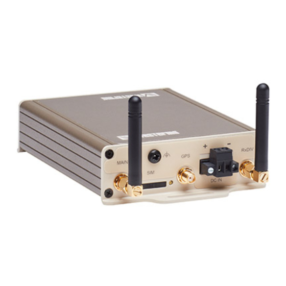
The MRD-415 comes in a very slim and robust casing which is ideal for wall mounting in small spaces, taking up very little space in a cabinet or similar. Connections come out on each end of the product, with antenna connectors on one side and Ethernet and serial interfaces on the other. -
Page 9: Available Models Mrd
Table 2. List of available models 3.3. Hardware Overview 3.3.1. Hardware Overview Description SIM-card drawer(s) Protective Earth Antenna connectors (3 pcs) Power connector Ethernet TX ports Factory reset switch LED indicators Serial port Table 3. Location of interface ports and LED indicators MRD-415 and MRD-455... -
Page 10: Connector Information
Connection speed LED Illustration Pin no. Signal Direction Description In/Out Transmitted/Received data In/Out Transmitted/Received data In/Out Transmitted/Received data Not connected Not connected In/Out Transmitted/Received data Not connected Not connected Table 5. Ethernet TX connections (RJ-45 connector), LAN 1-2 MRD-415 and MRD-455... -
Page 11: Serial Port (Dce Female)
GREEN 1 BLINK Signal strength indication: GREEN 2 1 - Very poor BLINKS 2 - Normal 3 - Very good GREEN 3 BLINKS GREEN 4 BLINKS GREEN 5 BLINKS GREEN 6 BLINKS Table 7. LED indicators MRD-415 and MRD-455... -
Page 12: Dimensions
3.6. Dimensions Dimensions are stated in mm. Figure 3. Dimensional drawing MRD-415 Figure 4. Dimensional drawing MRD-455 MRD-415 and MRD-455... -
Page 13: Installation
Snap on the product to the DIN-rail according to the figure. The MRD-415 includes an integrated mounting flange and can be attached to a panel or tray by means of screws, using the slots provided. Alternatively, it can be DIN rail mounted, using the DIN rail mounting kit. -
Page 14: Cooling
To eject the SIM card drawer, press the SIM card eject button using a suitable tool and remove the drawer, refer to figure for the location of the SIM card eject button. Insert the SIM card into the SIM card drawer with the contacts facing up, let chamfered corners align. MRD-415 and MRD-455... -
Page 15: Getting Started
Open a web browser on the PC and browse to http://192.168.2.200 (the default MRD IP address). A login box will popup. If the box fails to display, re-check the cable connections to the unit and the IP address settings of the PC. MRD-415 and MRD-455... -
Page 16: Factory Default Reset Switch
4. The router will now re-boot as normal with the factory default settings. NOTE Using the Factory default reset switch will erase all existing configuration settings and restore the factory default settings. This includes the network connection profile settings APN, user name and password. MRD-415 and MRD-455... -
Page 17: Specifications
Syslog (log files and remote syslog server) SNTP (NTP client) DHCP client DHCP server DDNS (Dynamic DNS update client) 25 x Configurable IPsec VPNs, processing power in relation to traffic over VPN sets limitation on number of VPNs. MRD-415 and MRD-455... -
Page 18: Interface Specifications
All other ports Connection RJ-45, auto MDI/MDI-X Cabling Shielded cable is not required, except when installed in railway applications as signalling and telecommunications apparatus and located close to rails Conductive chassis Number of ports Only applicable for MRD-455 MRD-415 and MRD-455... - Page 19 15 m/49 ft Connection 9 pin D-sub female Shielded cable Not required Conductive chassis Number of ports Cellular interface MRD-415 frequency bands MRD-455 frequency bands (MHz) (MHz) GSM 900, DCS 1800 GSM 900, DCS 1800 B1, B3, B8 B1, B5, B8...
-
Page 20: Type Tests And Environmental Conditions
MRD-455: ± 2 kV Power ports ± 2 kV Surge EN 61000-4-5 Signal ports MRD-415: ± 1 kV (Crit. B) MRD-455: ± 2 kV Power ports MRD-415: ± 0.5 kV (Crit. B) MRD-455: ± 2 kV Conducted RF immunity EN 61000-4-6 All ports 10 V (0.15-80 MHz) - Page 21 0-95% relative humidity Storage and transport Altitude Operational 2000 m/70 kPa Service life Operational 10 years MTBF MIL-217F MRD-415: 1 367,000 hours MRD-455: 911,000 hours Vibration IEC 61373 Enclosure Aluminum Weight MRD-415: 0.3 kg MRD-455: 0.4 kg Degree of protection EN 60529...
-
Page 22: Revision Notes
6. Revision Notes Revision Date Change description Rev. H 2021-11 Westermo logo updated, products MRD-315 and MRD-355 deleted from user guide, new information structure throughout the manual. Agency approval and standards complience EN/IEC 60950-1 deleded. MRD-415 and MRD-455... - Page 23 Westermo • Metallverksgatan 6, SE-721 30 Västerås, Sweden Tel +46 16 42 80 00 Fax +46 16 42 80 01 E-mail: info@westermo.com www.westermo.com 6623-2250 REV. H 2021 11 Westermo Network Technologies AB, Sweden...
Need help?
Do you have a question about the MRD-415 and is the answer not in the manual?
Questions and answers