Table of Contents
Advertisement
Quick Links
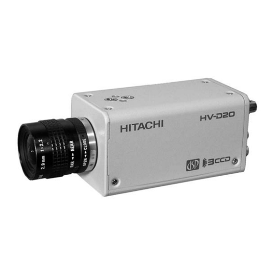
3-CCD Color Camera
MODEL HV-D20P
OPERATION MANUAL
Please read this operation manual carefully for proper operation, and keep it for future reference.
Note:
The model and serial numbers of your product are important for you to keep for your convenience and
protection. These numbers appear on the nameplate located on the bottom of the product. Please record these
numbers in the spaces provided below, and retain this manual for future reference.
Model No.
Serial No.
Hitachi Kokusai Electric Inc.
Advertisement
Table of Contents

Related Manuals for Hitachi HV-D20P


Summary of Contents for Hitachi HV-D20P
- Page 1 The model and serial numbers of your product are important for you to keep for your convenience and protection. These numbers appear on the nameplate located on the bottom of the product. Please record these numbers in the spaces provided below, and retain this manual for future reference. Model No. Serial No. Hitachi Kokusai Electric Inc.
-
Page 2: Important Safety Instructions
IMPORTANT SAFETY INSTRUCTIONS 1. Read Instructions 8. Accessories All the safety and operating instructions should Do not place this product on an unstable cart, be read before the product is operated. stand, tripod, bracket, or table. The product may fall, causing serious injury to a child or adult, and 2. - Page 3 built-in installation such as a bookcase or rack receptacles, and the point where they exit from unless proper ventilation is provided or the the product. manufacturer's instructions have been adhered 14. Lightning For added protection for this product during a lightning storm, or when it is left unattended and 11.
- Page 4 performance-this indicates a need for service. 19. Servicing Do not attempt to service this product yourself as 21. Replacement Parts opening or removing covers may expose you to When replacement parts are required, be sure the dangerous voltage or other hazards. Refer all service technician has used replacement parts servicing to qualified service personnel.
- Page 5 WICHTIGE SICHERHEITSANWEISUNGEN Waschzubers, in einem nassen Keller, in der Nähe 1. Alle Anweisungen lesen Betrieb Erzeugnisses sollten alle eines Schwimmbeckens usw. Sicherheits-und Bedienungsanleitungen gelesen 8. Aufstellung werden. Das Erzeugnis nicht auf einen unstabilen Wagen, Stand, Dreifuß, Träger oder Tisch stellen. 2.
- Page 6 erforderlich und dürfen nicht blockiert oder abgedeckt nur in ein schuko-Steckdose. Dies ist eine werden. Sicherheitsmaßnahme. Wenn Sie den Stecker Die Öffnungen sollten niemals dadurch blockiert nicht in die Steckdose stecken können, so wenden werden, daß, das Gerät auf ein Bett, ein Sofa, Sie sich bitte an ihren Elektriker, damit er die einen Teppich oder eine ähnliche Oberfläche veraltete...
- Page 7 qualifiziertes Wartungspersonal, wenn eine der 16. Eindringen von Fremdkörpern und Flüssigkeit Niemals Objekte irgendwelcher Art durch die folgenden Bedingungen vorliegt: Öffnungen in das Gerät schieben, da diese unter a. Wenn Netzkabel oder Stecker beschädigt ist. hoher Spannung stehende Teile berühren oder kurzschließen können, wodurch es zu Feuer oder b.
- Page 8 21. Ersatzteile Wenn Ersatzteile erforderlich sind, darauf achten, daß der Wartungstechniker nur die vom Hersteller festgelegten Ersatzteile oder Teile mit gleichen Charakteristiken ursprünglichen Teile verwendet. Unautorisierte Ersatzteile können Feuer, elektrischen Schlag oder sonstige Gefährdungen verursachen. 22. Sicherheitsprüfung Bitten Sie den Wartungstechniker nach der Vollendung von Wartung oder Reparaturarbeiten an diesem Erzeugnis um die Durchführung von Sicherheitsprüfungen, um zu bestimmen, daß...
- Page 9 MISES EN GARDE IMPORTANTES ou d’un bac á lessive, dans un sous-sol humide, 1. Lire les instructions Lire toutes les instructions de sécurité et de ou prés d’une piscine, etc. fonctionnement avant de faire fonctionner 8. Accessoires l’appareil. Ne pas placer l’appareil sur un chariot, un socle, 2.
- Page 10 l’appareil et le protéger de toute surchauffe, et Ne pas rendre vaine la measure de sécurité ouvertures ne devront donc être ni assurée par cette prise avec mise á la terre. obstruées ni recouvertes. Ne jamais obstruer les 13. Protection du cordon d’alimentation Acheminer les cordons d’alimentation de facon ouvertures en placant l’appareil sur un lit, un qu’on ne risque pas de marcher dessus ou de les...
- Page 11 provoquer un feu ou un choc électrique. d. Si l’appareil ne fonctionne pas normalement jamais renverser de liquide d’aucune sorte sur lorsqu’on observe les instructions d’utilisation. l’appareil. Ne régler que les commandes couvertes par le mode d’emploi ; en effet, un réglage incorrect 17.
- Page 12 22. Vérificaton de sécurité Aprés tout travail d’entretien ou de réparation de l’appareil, demander au technicien de réparation d’effectuer les vérifications de sécurité pour s’assurer que l’appareil est en bon état de marche. 23.Montage au mur ou au plafond L’appareil ne pourra être monté au mur ou au plafond que de la maniére recommandée par le fabricant.
-
Page 13: Table Of Contents
Table of contents IMPORTANT SAFETY INSTRUCTUIONS ・・ GAMMA ・・・・・・・・・・・・・・・・・・・・・・・・・・・・・・ Table of contents ・・・・・・・・・・・・・・・・・・・・・・・・・・ ・・・・・・・・・・・・・・・・・・・・・・・・・・・・・・・・・・ Standard composition ・・・・・・・・・・・・・・・・・・・・・ DTL-SUB ・・・・・・・・・・・・・・・・・・・・・・・・・・・・・ Overview EXT TRIGGER ・・・・・・・・・・・・・・・・・・・・・・・・・・・・・・・・ ・・・・・・・・・・・・・・・・・・・・・・・・ Features ・・・・・・・・・・・・・・・・・・・・・・・・・・・・・・・・・ OUTPUT/SYNC ・・・・・・・・・・・・・・・・・・・・・・・・ Notes to users ・・・・・・・・・・・・・・・・・・・・・・・・・・・・ FILE SET ・・・・・・・・・・・・・・・・・・・・・・・・・・・・・ Important safety notes ・・・・・・・・・・・・・・・・・・・ OTHER FUNC ・・・・・・・・・・・・・・・・・・・・・・・・... -
Page 14: Standard Composition
Operation Manual ・・・・・・・・・・・・・・・・・・・・・ * Part code Overview The HV-D20P is a three CCD color camera The high quality signal processing and image combining high picture quality and high stability compensating functions were unattainable in with the convenience of C mount optics. -
Page 15: Features
Features Single chip LSI camera signal processor Hitachi's leading edge processing technology A new digital noise reduction system provides 62 (0.18 μm, internal core 1.8V drive, and 3 million dB signal to noise ratio. Clear low noise images gates) is contained on a single newly developed are obtained even in high gain mode. -
Page 16: Notes To Users
These may Consult a Hitachi Denshi dealer for a selection of lead to failure or accident. fine lenses according to the application. Do not modify the camera or use the camera with Installation and storage sites external covers removed. -
Page 17: Ccd Properties
Cleaning reflected light. A photographer’s blower or lens brush can be used for clearing dust from the lens and optical 2) Fixed pattern noise filters. High ambient temperature can cause fixed Wipe dust from the case with a soft dry cloth. If pattern noise to appear throughout the scene. -
Page 18: Rear Panel Facilities
Name and function each section MENU button AWB/L button Press this button to display the camera setup DERECT mode: menu. The buttons U, D, L and R provide different Holding down this button for more than two seconds carries out functions depending on whether the menu is auto white balance (AWB). -
Page 19: Lens
Lens CAUTION: Observe the dimensions of the lens mounting selection as illustrated at the right. If the dimensions are not observed, do not use such a lens, because the lens and the camera will be damaged. Flange surface of lens 4.0mm or less Lens selection 2) Auto iris lens... -
Page 20: Video Signal Type Lens Adjustment
Video signal type lens adjustment Adjustment is required after replacing the lens or if using (1) Set the lens ALC control fully toward the average the camera for the first time. (Av ) position. (2) If auto iris hunting occurs, reduce the Iris Gain 1) Preparation setting. -
Page 21: Camera Mounting
(4) Auto iris operates, but scene is dark. Even if lens Camera mounting Level control is adjusted,the triangle mark to the left of the H mark is moved. The camera is provided with threaded screw holes at the Boost the gain. Set main menu Gain to 1-24 dB top and bottom. -
Page 22: System Example
System example Computer Image Processing & FA MULTI Camera PC + Frame Grabber Lens HV-D20 HITACHI MULTI System Power Supply Color Monitor REMOTE DC IN SYNC Remote Control RC-Z3 Junction Box Level JU-Z2 Converter Long JU-C20 cable Max 8 Microscope... -
Page 23: Menu Screen Operation
Menu Screen Operation 1. Menu Structure For settings in the camera, the MAIN and SPECIAL menus are available. 1-1 MAIN Menu Structure Press the MENU button and MAIN MENU appears on the screen to indicate the main menu mode. Again press the MENU button to extinguish the menu and enter the direct mode. There are a main function setup menu and three sub-menus, which are arranged hierarchically as shown below. - Page 24 1-2 SPECIAL Menu Structure To select the SPECIAL SET mode, press the MENU button for 2 seconds while holding down the U button. Thus, the SPECIAL SET menu can be displayed. To return to the DIRECT mode, press the MENU button again.
- Page 25 ■SPECIAL SET ■LENS ■LEVEL ■MASKING ■WHITE GATE LENS :-> LENS TYPE :DC WHITE GATE :OFF ENABLE MASKING WHITE GATE :-> IRIS MODE :AUT0 R GAIN R HUE: R SAT: GATE AREA(UP/DOWN) LEVEL :-> LENS SELECT:COSMICAR GATE AREA(LEFT/RIGHT) B GAIN Y HUE: Y SAT: MASKING :->...
- Page 26 2. MAIN MENU 1) CAM MODE : Camera mode • MANUAL : Nearly all function modes can be set. Use for detailed settings. • AUTO : Video level and white balance are automatic and a standard picture cam be observed without detailed settings.
- Page 27 2) WHITE BAL : White balance mode • PRST 3200K : The white balance condition is optimized at a color temperature of 3200K. • PRST 5600K : The white balance condition is optimized at a color temperature of 5600K. • MEM : White balance is automatically adjusted by the direct mode AWB button. •...
-
Page 28: Main Menu Sub Menu
5) SUB MENU 1 : The SUB menu 1 is brought up. 6) SUB MENU 2 : The SUB menu 2 is brought up. : The ALC is brought up. 7) ALC 8) FILE SELECT : Select among scene files 1, 2, 3, 4 and PRESET Camera setting data can be stored in four scene files. - Page 29 3. SUB MENU 1 1) M. BLACK : Master black level setting The master black level can be set in a range of -128 to 127. Pressing the R button increases a set value to make the black level higher, and pressing the L button decreases a set value to make the black level lower.
- Page 30 • AES : Auto electronic shutter operates in the Limit range setting. Optimum image level is obtained under strong light conditions. Effectively used for special optical systems such as microscope or fixed iris lens which do not have automatic light adjustment functions. Limit settings can be selected from 1/500 to 1/100000 second Note: AES cannot be used with Video Type Lens.
- Page 31 4) CCD MODE : CCD store mode • FLD : The field integration mode operation is performed (for ordinary purpose of application). • FRM : Frame integration mode; although vertical resolution is improved, image lag is slightly increased. Suggested for still images. At AES Shutter mode, camera sensitivity is reduced by about 6 dB.
-
Page 32: Sub Menu
4.SUB MENU 2 1) DYNA CHROMA : Dynamic chroma ON/OFF On setting improves coloration in bright scene components. 2) CHROMA GAIN : Level setting in chroma signal Setting range is -128 to 127. Press R and L to respectively raise or lower the chroma signal level. Press both L and R for about 2 seconds to set to 0. - Page 33 7) SHADING MODE : Auto shading setting • COLOR : Minimize vertical shading in image. Use for general scenes. • LUMINANCE : Equalizes vertical RGB signal levels. Use for special optics such as microscope or inspection devices. • FLAT : Equalizes overall image RGB signal levels. Effective for microscope perimeter shading and inspection devices.
-
Page 34: Alc
5. ALC 1) PEAK/AVE : Set auto level control for Peak or Average in 4 steps of 50/50, 25/75, 18/85 or 0/100. At high Average setting, background may be difficult to see in picture bright components. Increasing the Peak setting may render spotlighted components easier to see. 2) OVER RIDE : Auto iris level setting ALC level setting in range of -128 to 127 (about ±2 F stops). - Page 35 Note: The detect area shown in the under figure cannot be seen in the screen, the ALC control functions for the iris gate. PATTERN1 PATTERN2 PATTERN3 Detect area ALC PEAK/AVERAGE: 18/85 PEAK/AVERAGE: 18/85 PEAK/AVERAGE: 18/85 OVER RIDE OVER RIDE OVER RIDE...
-
Page 36: Special Set
6. SPECIAL SET Special menu allows more detailed settings for the camera. 1) LENS : Change to LENS menu. Set for optimum lens operation. Setting is required according to the lens type. 2) WHITE GATE : hang to WHITE GATE menu. White gate position setting. -
Page 37: Lens
7. LENS Menu for setting the lens functions 1) LENS Type : Sets type of auto iris. • : Iris opens in proportion to a DC control voltage. Also set to DC when not using an automatic iris. • Video : Lens iris is controlled by the video signal. Note: Auto electronic shutter (AES) cannot be used in the Video mode. - Page 38 3) LENS SELECT : Sets iris control voltage (Lens Type is DC mode). • Mode 1 : Control voltage is 1.5 to 5.5 V (e.g., Cosmicar with manual over-ride). • Mode 2 : Control voltage is 2.5 to 7.5 V. 4) IRIS SPEED : Sets auto iris speed (Lens Type is DC mode).
- Page 39 6) CLOSE Limit : (Lens Type is DC mode.) Observe the iris and adjust to precisely the largest value (smallest diameter). The setting range is from -128 to -1. Press R to increase and L to decrease the setting. Press L and R buttons simultaneously for about 2 seconds to set to -85 for Cosmicar or to -65 for Others.
-
Page 40: White Gate
8. WHITE GATE Sets the area (window) position for use as white balance control data. Adjust the window to a white or gray monochrome portion of the screen. 1) WHITE GATE : White gate ON/OFF ■WHITE GATE • ON : In real time auto white balance operation or GATE execution of memory auto white balance, a video GATE AREA(UP/DOWN) -
Page 41: Level
9. LEVEL This menu screen allows you to set up a black level and gain of R/B video signal. 1) ENABLE : Level control ON/OFF setting. 2) R GAIN : R gain level setting The allowable setting range is -128 to 127. Pressing the R button increases a numeric value to make the R video signal gain higher. -
Page 42: Masking
5) Initialize : Returns level menu settings to preset values. Simultaneously press L and R for about 2 seconds. 6) File select : Selects scene files 1 - 4 and preset. 10. MASKING Menu for setting the masking. 1) MASKING: MASKING ON/OFF setting 2) R HUE: Change red color phase 3) Y HUE: Change yellow color phase 4) G HUE: Change green color phase... -
Page 43: Gamma
14) Initialize : Returns level menu settings to preset values. Simultaneously press L and R for about 2 seconds. 15) File select : Selects scene files 1 - 4 and preset. 11. GAMMA Menu for setting the gamma parameters. If dark component contrast is inadequate, adjusting the gamma parameters allows detailed adjustment of the Sub-menu 2 Contrast (Off, Low, High). -
Page 44: Dtl
12. DTL Menu for setting detail parameters 1) DTL FREQUENCY : DTL amplifying frequency changeover. • : The lower band frequency is amplified. • : The standard amplification is performed. • HIGH : The high band frequency is amplified. Finer contour correction is carried out. - Page 45 7) Width : Sets color phase range for setting Setting range is -128 (narrow) to 127 (wide). Since the VBS output is shown as monochrome on the monitor, a monochrome indication can also be used for an approximate setting. Press both L and R for about 2 seconds to set to 0.
-
Page 46: Dtl-Sub
13. DTL SUB 1) LEVEL DEP : Dependent level setting Detail amount, and noise, can be reduced in scene dark components. Setting range is -128 to +127. Press the R button to increase the value, reduce the detail amount and expand the video signal level range. -
Page 47: Ext Trigger
14. Ext trigger The external trigger function is used with a frame grabber to obtain an image of an object at a desired exposure time. Settings can provide images at various timings. The exposure time can be controlled by the external trigger pulse width. 1) Trigger mode : Selects external trigger mode •... - Page 48 The trigger and CCD mode timing can be combined to obtain image timing as indicated in the figures. a) MODE: MODE1, CCD MODE: FLD μ m ore than 64 TRIGG ER PO LARITY: m ore than 2 fields PO SITEVE External trigger pulse TRIGG ER PO LARITY: NEG ATEVE...
- Page 49 b) MODE: MODE1, CCD MODE: FRM μ m ore than 64 External trigger pulse m ore than 2 fields Strobe timing ~ DELAY TIME:3H O DD Exposure time EVEN Video signal output O DD EVEN EVEN O DD SYNC reset SYNC reset W E pulse output Note: When the flashlight is not used, the even and odd video signal levels are difference.
- Page 50 c) MODE: MODE2, CCD MODE: FLD External trigger pulse m ore than 2 fields m ore than 2 fields Exposure tim e Video signal output EVEN EVEN EVEN EVEN EVEN SYNC reset SYNC reset W E pulse output d) MODE: MODE2, CCD MODE: FRM External trigger pulse more than 2 fields more than 2 fields...
- Page 51 Note: Prohibited period of the external trigger pulse timing For each external trigger mode, when the end edge of external trigger pulse is input in the prohibited period (shown in the under figure), the picture is not output after the SYNC reset. Please input the repetition period of trigger pulse with the following specification, to avoid the trigger input to an above prohibited period.
-
Page 52: Output/Sync
15. OUTPUT/SYNC On this menu screen, you can make signal changeover for output to the D-SUB connector and phase adjustment for external synchronization. 1) OUTPUT : Output mode changeover • R, G, B :The R, G and B video signals are output to the D-SUB connector. •... - Page 53 7) GL MODE : GL signal input changeover • VBS : The VBS signal or BBS (black burst) signal is input as an external synchronizing signal. • HD/VD : The HD/VD signal is input as an external synchronizing signal. Note: During external sync with HD and VD signals, be sure to use either RGB or Y, B-Y, R-Y output signals.
-
Page 54: File Set
16. File set Use for transferring scene file data to another file or setting all data to preset values. : Selects scene file 1 - 4 or preset for copy data. 1) FILE SELECT : Selects file for storing scene file data. 2) STORE FILE : Press L and R for more than 1 second to transfer selected scene file data to store 3) STORE... -
Page 55: Other Func
17. OTHER FUNC 1) NEGA : NEGA image ON/OFF At the ON setting, the output video becomes negative image. 2) FLARE : Flare compensation on/off Corrects for extraneous reflections in the optical and CCD systems which end to weaken bright image components. - Page 56 8) REMOTE TYPE : Selects between modes 1 and 2. • MODE 1: Select to use the same computer commands as other camera models (e.g., HV-C20 series). • MODE 2: Normal setting. Use for the RC-Z3 remote control box. 9) ID/TITLE : Change to ID/TITLE menu 10) Pixel correct : White flaw compensation on/off Normally set to on.
-
Page 57: Id/Title
18. ID/TITLE ID and title display position and data setting menu. 1)ID : ID display position setting Once an ID is assigned, it becomes possible to control a particular camera unit remotely from a personal computer according to its ID. That is, multiple camera units can be remote-controlled individually from one persona computer. - Page 58 3) DATA SET : The DATA SET screen comes up. : Enter an ID code consisting of three characters. Alphanumeric upper-case characters and a space character are permitted. TITLE : Enter a TITLE consisting of up to 12 characters. Alphanumeric upper-case characters, special symbols and a space character are permitted. Note: The symbol "...
-
Page 59: How To Attain Better Images
How to Attain Better Images Black Balance Adjustment Adjust black balance to provide proper color tone at a dark part of video image. In the following cases, be sure to carry out black balance adjustment. • When using the camera first after purchasing it. •... -
Page 60: White Balance Adjustment
・ Carry out AUTO BLACK again. If this message appears in repeated attempts, it is necessary to inspect the inside of the camera. In this case, notify your local Hitachi Denshi sales agent or Hitachi Denshi service office White Balance Adjustment Carry out white balance adjustment when the illumination condition (color temperature) is changed. - Page 61 Error message Procedure AUTO WHITE:NG ・ Turn off the color bar. CHANGE TO CAM TRY AGAIN AUTO WHITE:NG ・ Set up WHITE BAL:MEM. CHANGE TO MEMORY MODE TRY AGAIN AUTO WHITE:NG ・ White balance cannot be made due to insufficient illumination. LOW LIGHT ・...
-
Page 62: Realtime Auto White
Realtime Auto White The camera detects a white part in the image by itself, and its internal microcomputer automatically adjusts white balance in real time. Use this function in case that the color temperature varies with time (e.g., from morning to day to night). 1. -
Page 63: Alc (Auto Level Control)
4. In the DIRECT mode, while holding down U button and D button for more than two seconds and press the D button or in the MENU mode, carry out AUTO SHADING. Thus, color shading in the image is corrected automatically. Notes 1) When using the camera for the first time or after replacing the lens, just be sure above instructions. - Page 64 OPEN LIMIT CLO SE LIMIT +6dB to +24dB to 1/100,000s AGC+AUTO IRIS+AES AGC range AES range AUTO IRIS range (DC type lens) AGC+AUTO IRIS AGC range AUTO IRIS range (DC type/VIDEO type lens) AUTO IRIS+AES AUTO IRIS range AES range (DC type lens) AGC+AES AGC range...
-
Page 65: Long-Time Store Mode
Long-Time Store Mode In case that illumination on the subject is insufficient, just increasing the gain of the camera may cause an increase in noise, resulting in an unclear image. In such a situation, it is advisable to select the long-time store mode using the external memory. - Page 66 F ra m e sto r e m o d e In th e fra m e s to re m o d e , e a ch o f th e C C D lin e s A a n d B is re a d o u t in d ivid u a lly. E v e n fie ld C C D lin e A T h e re fo re, th e ve rtica l re s o lu tio n is...
-
Page 67: Rc-Z3 Remote Control Panel
RC-Z3 Remote Control Panel All camera menu items can be operated remotely by connecting the RC-Z3 Remote Control Panel. Connect the panel as follows. (1) Set camera internal switch SW806 to RC-Z3. See internal switch selection on page 63. (2) Open the SPECIAL SET menu and set the camera communications rate to 9600 bps.(see page 42). Operation (1) Direct control The following items can be controlled directly as well as from the control panel. - Page 68 (3) Setting data store Setting data (menu and direct control items) are not automatically stored when using the RC-Z3. Press the RC-Z3 STORE button and the SCENE FILE button of the location for storing the data. Note: Use care since the data are lost if the application is changed or the power cut off without storing.
-
Page 69: Rc-Z3 Panel Facilities
15 TALLY/CALL button 1. RC-Z3 panel facilities 16 SHUTTER button 17 CONTRAST button CAMERA CONTROL PANEL RC-Z3 18 ULTRA GAIN button ULTRA A.WHT CONTROL switch TALLY/CALL SHUTTER CONTRAST CONTROL GAIN ULTRA A.WHT button LOCK EXTENDER A.BLK FUNCTION A.BLK button EXTENDER BAR/CAM switch HIGH AUTO... - Page 70 CONTROL switch ・ON (red LED) : Normal camera control from. ・LOCK (red LED) : All controls and switch RC-Z3 has locked at present settings, except IRIS M. BLK . Prevents accidental or unauthorized operation. ・OFF (green LED): Operation inhibited from RC-Z3. Operate from camera controls and switches. EXTENDER LED This Extender LED is always extinguished using with the HV-D20 camera.
- Page 71 (1) File selection Press the following buttons to change the camera and RC-Z3 settings. ・PRESET: Produces the standard setting mode ・SCENE FILE 1: FILE-1 (scene file 1) setting mode ・SCENE FILE 2: FILE-2 setting mode ・SCENE FILE 3: FILE-3 setting mode ・SCENE FILE 4: FILE-4 setting mode Note: The pressed SCENE FILE button lights, then flashes when the application file data are changed.
- Page 72 Store operation notes: 1. After adjustment and operation with the RC-Z3, neglecting the Store operation before pressing a file button loses the adjustment and setting item data. The output is the designated file data prior to adjustment and operation. After adjustment and operation with the RC-Z3, neglecting the Store operation before cutting off the power loses the adjustment and setting item data.
- Page 73 TALLY/CALL button TALLY/CALL button lights when pressed. However, function is ineffective in the HV-D30 camera. SHUTTER button Shutter on/off; lights when on. Note: When CAM MODE AUTO, the Shutter button is ineffective. CONTRAST button Contrast on/off; lights when on. Note: Inoperative with gamma off (gamma set to off at SUB MENU 2 of menu mode). ULTRA GAIN button Ultra gain on/off.
- Page 74 IRIS switch Sets lens iris mode. Press the switch upward to set the mode in the sequence AUTO→REMOTE→MANUAL. ・ AUTO : Automatic iris operation ・ REMOTE: Iris is adjusted by the iris control ・ MANUAL: Set the lens A/M switch to M and adjust the lens iris ring manually. Note: When using the video type lens, REMOTE and MANUAL function is ineffective in the HV-D30 camera.
- Page 75 DTL switch Camera detail setting. Press the switch to select in the sequence VARIABLE→LOW→NORMAL→HIGH. During VAR, the mode indicator LEDs show the detail amount; in the menu mode, the MAIN MENU screen DTL setting is OFF or VAR. IRIS control Adjusts the lens iris as follows.
-
Page 76: Function Selection By Internal Switch Setting
Function Selection by Internal Switch Setting 1. SW806 2. SW401 For connection with the remote control box RC-Z3, For selection SYNC or HD/VD output and GL or set SW806 to the RC-Z3 position. HD/VD input of multi connector. For connection with the personal computer, set At shipment from factory, SW401 is set at the OUT SW806 to the RS-232C position. -
Page 77: Connectors
Connectors MULTI connector (DMSH-15S) Pin No. Signal designation PLAG : Housing KEC-15P R/R-Y/C OUT Pin contact JK-SP2140 G/Y/Y OUT Cover JK-C151C B/B-Y/VBS WE OUT * Use No.4-40UNC plug retaining screws. VIDEO GND VIDEO GND VIDEO GND UNREG +12V IN TRIG IN HD IN/HD OUT/ SYNC OUT VD IN/GL IN... - Page 78 REMOTE connector (HR10A-7R-4S) LENS connector (D4-151N-100) Pin No. Signal designation Pin No. Signal designation +12V output +12V RXD/SD input TXD/SD output Control Plug: HR10A-7P-4P Plug: E4-191J-100...
- Page 79 DC IN connector (R03-R3M2) Pin No. Signal designation +12V input Plug:R03-P3F...
-
Page 80: Specifications
Specifications 1) Color system 1/2-inch, F1.6 prism 2) Optical system R, G, B 3 CCD 3) Imaging system Corresponding to 1/2-inch interline transfer CCD 4) Picture elements (with microlenses) Total pixels 795 (H) × 596 (V) Effective pixels 752 (H) × 582 (V) Effective image area 6.35 (H) ×... - Page 81 16) Vertical contour compensation C mount (flangeback 17.25 mm in air) 17) Lens mount AGC (0 to +24 dB) 18) Sensitivity selection or GAIN (0 to +24 dB step1dB or step 3 dB on remote control menu) DTL level and frequency 19) Detail control 4 Files 20) Scene files...
- Page 82 65 (W) × 65 (H) ×130 (D) mm 26) Dimensions Approx. 400 g (not including lens) 27) Mass Operating -10 to 45 ℃ 28) Ambient temperature Storage -20 to 60 ℃...
-
Page 83: Input/Output Signals
Input/Output Signals 1. Input signal conditions 1) Genlock input (MULTI connector) ・ VBS 1.0 Vp-p ±3 dB or black burst/75 ohm or high (BNC) (sync 0.3 ±0.1 Vp-p, burst 0.3 ±0.1 Vp-p) ・ HD/VD 2 to 5 Vp-p, negative (D-sub connector) Note: Genlock input and Sync output are selected by internal input/output switch. - Page 84 3) Component output (MULTI connector) Y : 1.0 Vp-p/75 ohm R-Y: 0.7 Vp-p/75 ohm B-Y: 0.7 Vp-p/75 ohm 4) RGB output (MULTI connector) 0.7 Vp-p/75 ohm 0.7 Vp-p/75 ohm 0.7 Vp-p/75 ohm Note: YC/VBS, component and RGB MULTI connector outputs are selected by menu. 5) Sync outputs (MULTI connector) 2 Vp-p/75 ohm 2 Vp-p/75ohm...
-
Page 85: Major Accessories
Major accessories Camera control box, RC-Z3 Camera Junction box, JU-Z2 RS-232C level converter JU-C20 Dimensions 2-1/4" UNC (DEPTH:7) 32.5 V I D E O M E N U A S C F I L E P O W E R A...
Need help?
Do you have a question about the HV-D20P and is the answer not in the manual?
Questions and answers