Table of Contents
Advertisement
Quick Links
MODEL HV-D27
MODEL HV-D
MODEL HV-D
MODEL HV-D
Please read this operation manual carefully for proper operation, and keep
Please read this operation manual carefully for proper operation, and keep
Please read this operation manual carefully for proper operation, and keep
Please read this operation manual carefully for proper operation, and keep
it for future reference.
it for future reference.
it for future reference.
it for future reference.
Note:
Note:
Note:
Note:
The model and serial numbers of your product are important for you to keep for your
convenience and protection. These numbers appear on the nameplate located on the bottom of
the product. Please record these numbers in the spaces provided below, and retain this manual
for future reference.
Model No.
Model No.
Model No.
Model No.
OPERATION MANUAL
OPERATION MANUAL
OPERATION MANUAL
OPERATION MANUAL
Serial No.
Serial No.
Serial No.
Serial No.
Hitachi Denshi, Ltd.
3-CCD Color Camera
3-CCD Color Camera
3-CCD Color Camera
3-CCD Color Camera
27 HV-D
HV-D37
27
27
HV-D
HV-D
37
37
37
Advertisement
Table of Contents

Related Manuals for Hitachi HV-D27


Summary of Contents for Hitachi HV-D27
- Page 1 3-CCD Color Camera 3-CCD Color Camera 3-CCD Color Camera 3-CCD Color Camera MODEL HV-D MODEL HV-D27 27 HV-D HV-D37 MODEL HV-D MODEL HV-D HV-D HV-D OPERATION MANUAL OPERATION MANUAL OPERATION MANUAL OPERATION MANUAL Please read this operation manual carefully for proper operation, and keep...
-
Page 2: Important Safety Instructions
IMPORTANT SAFETY INSTRUCTIONS 1. Read Instructions 1. Read Instructions 1. Read Instructions 1. Read Instructions All the safety and operating instructions should be read before the product is operated. 2. Retain Instructions 2. Retain Instructions 2. Retain Instructions 2. Retain Instructions The safety and operating instructions should be retained for future reference. - Page 3 12. Grounding or Polarization 12. Grounding or Polarization 12. Grounding or Polarization 12. Grounding or Polarization This product is equipped with a three-wire grounding-type plug a plug having a third (grounding) pin. This plug will only fit into a grounding-type power outlet. This is a safety feature. If you are unable to insert the plug into the outlet, contact your electrician to replace your obsolete outlet.
- Page 4 21. Replacement Parts 21. Replacement Parts 21. Replacement Parts 21. Replacement Parts When replacement parts are required, be sure the service technician has used replacement parts specified by the manufacturer or have the same characteristics as the original part. Unauthorized substitutions may result in fire, electric shock, or other hazards. 22.
- Page 5 WICHTIGE SICHERHEITSANWEISUNGEN 1. 1. 1. 1. Alle Alle Alle Anweisungen lesen. Alle Anweisungen lesen. Anweisungen lesen. Anweisungen lesen. Vor Betrieb des Erzeugnisses sollten alle Sicherheits-und Bedienungsanleitungen gelesen werden. 2. Die Anweisungen aufbewahren. 2. Die Anweisungen aufbewahren. 2. Die Anweisungen aufbewahren. 2.
- Page 6 11. Stromversorgung 11. Stromversorgung 11. Stromversorgung 11. Stromversorgung Dieses Erzeugnis sollte nur an der auf dem Typenschild angegebenen Stromversorgungsart betrieben werden. Wenn Sie nicht sicher sind, was für eine Stromversorgung Sie haben, so wenden Sie sich bitte an Ihren Erzeugnishändler oder an das lokale Elektrizitätswerk. Beziehen Sie sich für Batteriebetrieb oder andere Stromquellen vorgesehene Erzeugnisse bitte auf die Bedienungsanleitungen.
- Page 7 20. Besch 20. Beschädigung, die Wartung erfordert digung, die Wartung erfordert 20. Besch 20. Besch digung, die Wartung erfordert digung, die Wartung erfordert Ziehen Sie den Stecker dieses Erzeugnisses aus der Steckdose und wenden Sie sich an qualifiziertes Wartungspersonal, wenn eine der folgenden Bedingungen vorliegt: a.
- Page 8 MISES EN GARDE IMPORTANTES 1. Lire les instructions 1. Lire les instructions 1. Lire les instructions 1. Lire les instructions Lire toutes les instructions de sécurité et de fonctionnement avant de faire fonctionner l’appareil. 2. Conserver ces instructions 2. Conserver ces instructions 2.
- Page 9 12. Mise 12. Mise 12. Mise 12. Mise á la terre ou polarisation la terre ou polarisation la terre ou polarisation la terre ou polarisation L’appareil est doté d’une fiche trifilaire avec mise á la terre, dont la troisiéme broche assure la mise á la terre. Cette fiche ne rentrera que dans les prises trifilaires de mise á...
- Page 10 21. Pi 21. Piéces de rechange 21. Pi 21. Pi ces de rechange ces de rechange ces de rechange Si l’on a besoin de piéces de rechange, veiller á ce que le technicien de réparation utilise exclusivement les piéces de rechange spécifiées par le fabricant ou des piéces ayant les mêmes caractéristiques que les piéces d’origine.
-
Page 11: Important Notice
WARNING Changes or modifications not expressly approved by Hitachi Denshi responsible for compliance could void the user’s authority to operate the equipment. For Canada This product does not exceed the class A/class B limits for radio noise emissions from digital apparatus as set out in the radio interference regulations. -
Page 12: Table Of Contents
Table of contents IMPORTANT SAFETY INSTRUCTUIONS IMPORTANT NOTICE Table of contents Standard composition Overview Features Notes to users Notes for safety Operating considerations CCD properties Name and function each section Lens caution System examples Menu screen operation Menu Structure MAIN MENU SUB MENU 1 SUB MENU 2 BLACK ADJ... - Page 13 How to Attain Better images Black Balance Adjustment Dark shading compensation White Balance Adjustment Real time Auto White Auto Shading Correction ALC (Auto level control) Lock scan mode shutter speed setting Long-Time Store Mode RC-C10 Remote Control Box Function Selection by internal Switch Setting Connectors Specifications Input/Output Signals...
-
Page 14: Standard Composition
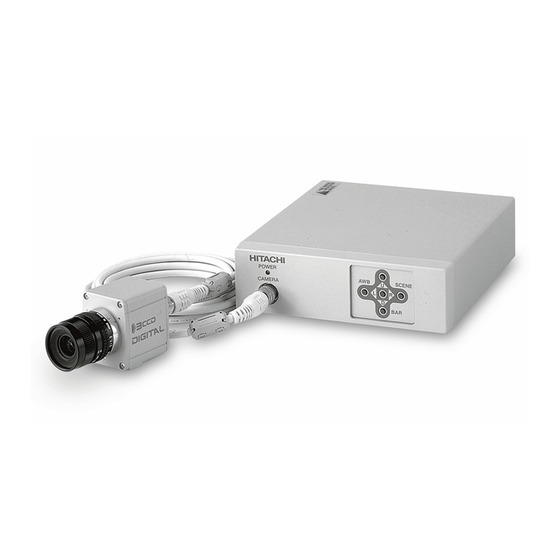
20m(67ft: C-202KAJ) Power plug, RM12BPG-3S (JMR0152*) Operation Manual Function labels for RC-C10 Remote Control Box * Part code Overview The HV-D27 and HV-D37 from Hitachi are separate head and control unit type 3 element color cameras respectively incorporating 1/2-inch 1/3-inch pixel image sensors. -
Page 15: Notes To Users
(thunder audible). Protect the camera from rain if using it outdoors. In event the camera shows any abnormality, switch off the camera and disconnect the power cord. Contact a Hitachi Denshi service representative. Operating considerations Operating considerations Operating considerations Operating considerations Power supply Check that the supplied voltage is between 10.5 and 17 VDC. -
Page 16: Ccd Properties
The correct lens is important for deriving optimum performance from the camera. Consult a Hitachi Denshi dealer for a selection of fine lenses according to the application. Installation and storage sites The following types of environment can impair performance, lead to damage, pose safety hazards and shorten the useful life of the camera. - Page 17 3) Moire Interaction between patterns produce additional "phantom" pattern to appear. The CCD picture elements (pixels) are arranged in a pattern, which can interact with a pattern in the scene (e.g., a performer wearing a finely striped necktie) to result in a Moire pattern.
-
Page 18: Name And Function Each Section
Name and function each section... -
Page 19: Lens Caution
Camera performance depends greatly on the choice of lens. Note the following points when choosing the lens. Image ghosting can occur if the lens is not matched to the CCD. Choose 1/2-inch for the HV-D27 and 1/3-inch for the HV-D37. -
Page 20: System Examples
System examples... -
Page 21: Menu Screen Operation
Menu Screen Operation 1. Menu Structure For settings in the camera, the MAIN and SPECIAL menus are available. 1-1 MAIN Menu Structure Press the SEUTP button and MAIN MENU appears on the screen to indicate the main menu mode. Again press the SETUP button to extinguish the menu and enter the direct mode. There are a main function setup menu and three sub-menus, which are arranged hierarchically as shown below. - Page 22 1-2 SPECIAL Menu Structure To select the SPECIAL SET mode, press the SETUP button for 2 seconds while holding down the U button. Thus, the SPECIAL SET menu can be displayed. To return to the DIRECT mode, press the SETUP button again. The SPECIAL SET menu indicates a list of items, and each special items subsidiary menus are available.
-
Page 23: Main Menu
MAIN MENU CAM MODE Camera mode In this mode, you can set up most functions. Use the MANUAL mode for detail MANUAL settings. The video level and white balance are adjusted automatically. Without having to AUTO make detail settings, you can display images under standard conditions. On the Main menu, some function items have the asterisk (*) mark. - Page 24 GAIN Gain mode The gain level is set to 0 dB. NORMAL The gain level is set to a value specified at GAIN HIGH on the SUB menu 1. HIGH The gain level is set to a value specified at GAIN MAX on the SUB menu 1. An increase in gain is controlled automatically.
-
Page 25: Sub Menu 1
SUB MENU 1 M BLACK Master black level setting The master black level can be set in a range of -128 to 127. Pressing the R button increases a set value to make the black level higher, and pressing the L button decreases a set value to make the black level lower. - Page 26 EXT FIELD-ON-DEMAND FANCTION Frame-on-demand refer to a function for picking up rapidly moving objects by applying a trigger pulse input at a desired timing to provide a desired or a fixed exposure time. The function is effective since the object is always taken at the same position in the picture.
- Page 27 5 CCD MODE CCD store mode changeover The field store mode operation is performed (for ordinary purpose of application). FRM Frame store mode operation is performed. The vertical resolution can be increased but the degree of after-image becomes slightly higher. It is therefore recommended to use the FRM function when taking a still image.
-
Page 28: Sub Menu
.SUB MENU 2 DYNA CHROMA Dynamic chroma ON/OFF With knee on, setting the dynamic chroma on improves coloration in bright portions of the scene. CHROMA GAIN Level setting in chroma signal The chroma signal level can be set in the range of -128 to +127. Respectively press the R button to increase and the L button to decrease the chroma signal level. -
Page 29: Alc
BLACK ADJ The BLACK ADJ menu is brought up. 10 MESSAGE RTN Message display ON/OFF A message indicating the result of AWB/ABB execution in the DIRECT mode is displayed. OFF A message indicating the result of AWB/ABB execution in the DIRECT mode is not displayed. Peak/AVE: Sets ALC detect signal peak/average ratio. -
Page 30: Black Adj
BLACK ADJ 1) Auto black: Automatic black balance adjustment Press the R button to activate automatic adjustment. See page 26. 2) Dark Shad: Automatic dark shading adjustment Press the R button to activate automatic adjustment. See page 26. SPECIAL SET REMOTE Remote control baud rate setting For baud rate setting, use the L and R buttons. -
Page 31: Alc Gate
ALC GATE Menu for setting light sensing areas used for ALC data. 1) Gate sel: Select sensor area arrangement pattern. Preset 1 - preset 5: 5 fixed arrangement patterns. Memory 1 and memory 2: Arrangement patterns from Gate Set. 2) Gate set: Changes to ALC gate pattern setting screen. Desired of 64 areas can be set. -
Page 32: Masking
R GAIN R gain level setting The allowable setting range is -128 to 127. Pressing the R button increases a numeric value to make the R video signal gain higher. Pressing the L button decreases a numeric value to lower the R video signal gain. For 0 (zero) setting, hold down both the L and R buttons for approx. -
Page 33: Output/Sync
13 INITIALIZE: Mask settings are initialized to factory values for each application file. Simultaneously press the L and R buttons for about 2 seconds to return the selected files to the factory settings. See Page 25 for the factory settings of each application file. 11 OUTPUT/SYNC On this menu screen, you can make signal changeover for output to the D-SUB connector and phase adjustment for external synchronization. -
Page 34: Id/Title
SC.COARSE Coarse adjustment of subcarrier phase Using the L or R button, select one of the following phases; 0º, 90º, 180º and 270º. SC.FINE Fine adjustment of subcarrier phase The allowable setting range is -128 to 127. There is no direct relationship between a numeric value and a degree of phase. If the relevant range is exceeded, the SC COARSE setting is updated automatically to permit continuous adjustment. -
Page 35: File Title
ID/TITLE Setup Procedure With the cursor located at DATA SET, press the D button. The cursor moves to the ID data set position an the first character flashes. Using the L, R, U and D buttons, select an input character. Press the SET UP button, and the selected character will be entered. -
Page 36: Gamma
and expand the video signal level range. Press L button to decrease the value and reduce the range. Set to 0 by simultaneously pressing the L and R buttons for about 2 seconds. CRISP Crispness level setting Reduces noise when DTL setting is in the range of -128 to 127. However, at high settings, some loss of sharpness occurs in detailed scene components. -
Page 37: Scene File
Scene files (FILE-1,FILE-2,FILE-3) The camera setting data can be saved to 3 scene files. This function enables storing the optimum settings for 3 sets of special but recurring scene conditions for later recall when setting up the camera. 1. Items stored in scene files The following items can be stored in each scene file. - Page 38 Common file settings The settings of these items apply to all files. They cannot be set differently for each file. The table indicates the factory settings.
-
Page 39: How To Attain Better Images
AUTO BLACK NG is necessary to inspect the inside of the camera. In this case, notify your local Hitachi Denshi sales agent or Hitachi Denshi service office Dark shading compensation When the camera cable length is changed, horizontal color shading can occur in the image. The shading can be compensated as follows. -
Page 40: White Balance Adjustment
White Balance Adjustment Carry out white balance adjustment when the illumination condition (color temperature) is changed. 1. In the MENU mode, set up WHITE BAL: MEM 3200K or MEM 5600K. 2. Turn off the MENU screen to select the DIRECT mode. 3. - Page 41 Color temperature too low for optimum adjustment. AUTO WHITE NG Set WHITE BAL to MEM 3200 K mode. C. TEMP LOW CHANGE TO MEM 3200K TRY AGAIN...
-
Page 42: Realtime Auto White
Realtime Auto White The camera detects a white part in the image by itself, and its internal microcomputer automatically adjusts white balance in realtime. Use this function in case that the color temperature varies with time (e.g., from morning to day to night). 1. -
Page 43: Lock Scan Mode Shutter Speed Setting
Lock scan mode shutter speed setting Press the Setup button and open the main menu, then open Sub menu 1. Set the cursor to SHUTTER by pressing D, select the VARIABLE position with the L-R buttons, again press D to shift to the variable items. Press the L and R buttons to set the shutter speed in the range indicated below. -
Page 44: Long-Time Store Mode
Long-Time Store Mode In case that illumination on the subject is insufficient, just increasing the gain of the camera may cause an increase in noise, resulting in an unclear image. In such a situation, it is advisable to select the long-time store mode using the external memory. Thereby, the image can be brighter and clearer according to the stored amount of image. -
Page 45: Rc-C10 Remote Control Box
SC COARSE M.BLK SC FINE *Use Auto fixed for the HV-D27 and HV-D37. (2) Menu control Items not mentioned in the above list are controlled by menu settings. The control box Option 1, Option 2, Auto White and Auto Black buttons are assigned to menu operating buttons. When AUTO WHITE and AUTO BLK are not indicated in the menu, the functions are conducted directly from the control box buttons. -
Page 46: Function Selection By Internal Switch Setting
Function Selection by Internal Switch Setting SW701 For connection with the remote control box RC-C10, set SW701 to the RC-C10 position. For connection with the personal computer, set SW405 to the RS- 232C position. At shipment from factory, SW405 is set at the RC-C10 position. Connectors MULTI connector (SDEB-9S) REMOTE connector (HR10A-7R-4S) - Page 47 TRIG connector (HR10A-10R-12PB) Pin No. Signal designation HD input VD/TRIG input Y/C connector (TCS-7547-01-401) 12V-IN connector (RM12BRD-3PH) Pin No. Signal designation Pin No. Signal designation Y GND +12V input C GND Y output C output...
-
Page 48: Specifications
Specifications (1) Color system NTSC PAL (2) Optical systems 1/2-inch F1.6 prism 1/3-inch F2.2 prism (3) Imaging systems R,G,B 3-chip (4) Imaging device 1/2-inch interline 1/3-inch interline (with micro lenses) (with micro lenses) Total pixels NTSC 811(H) 508(V) 795(H) 596(V) Effective pixels NTSC 768(H) 494(V) 752(H) 582(V) - Page 49 (16) Color bar SMPTE FULL (17) Power supply voltage 12V rated Stable operation is ensured with DC power supply 10.5 to 17 V No ripple and noise shall occur (18) Power consumption Approx.10.5 (19) Dimensions Camera head 38.5 (W) 46 (H) 42 (D)mm Caamera control unit 150 (W) 45 (H) 170 (D)mm (20) Mass...
-
Page 50: Input/Output Signals
Input/Output Signals 1. Input signal (1) Genlock input VBS 1.0 Vp-p 3 dB or black burst, 75 or high impedance (BNC) (Sync 0.3 0.1 Vp-p, burst 0.3 0.1 Vp-p) HD/VD TTL level (TRIG connector) (2) Serial data (4 pin connector) 1.5 Vp-p 3 dB, high impedance (in connection with RC-C10) RS-232C level (in connection with personal computer) -
Page 51: Major Accessories
C-202KAJ (20m) Cable length setting (for seaviceman information) When it is needed to change the cable length, contact your local Hitachi Denshi sales representative. Note the following points when replacing the camera cable. (1) Set CCU internal switches SW201 and SW202 according to the cable length. Remove the CCU cover and set the switches as indicated. -
Page 52: Dimensions
Dimensions...
Need help?
Do you have a question about the HV-D27 and is the answer not in the manual?
Questions and answers