Table of Contents
Advertisement
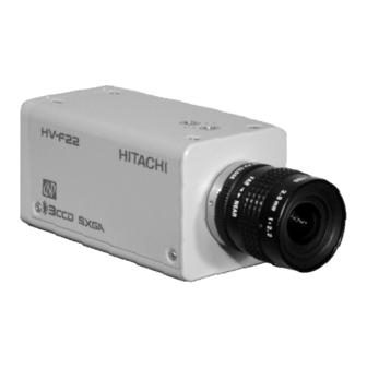
3-CCD Color Camera
MODEL HV-F31F
HV-F22F
OPERATION MANUAL
Please read this operation manual carefully for proper operation, and keep it for future reference.
Note:
The model and serial numbers of your product are important for you to keep for your convenience and
protection. These numbers appear on the nameplate located on the bottom of the product. Please record these
numbers in the spaces provided below, and retain this manual for future reference.
Model No.
Serial No.
Hitachi Kokusai Electric Inc.
Advertisement
Table of Contents

Related Manuals for Hitachi HV-F22F


Summary of Contents for Hitachi HV-F22F
- Page 1 The model and serial numbers of your product are important for you to keep for your convenience and protection. These numbers appear on the nameplate located on the bottom of the product. Please record these numbers in the spaces provided below, and retain this manual for future reference. Model No. Serial No. Hitachi Kokusai Electric Inc.
-
Page 2: Important Safety Instructions
IMPORTANT SAFETY INSTRUCTIONS 1. Read Instructions All the safety and operating instructions should be read before the product is operated. 2. Retain Instructions The safety and operating instructions should be retained for future reference. 3. Heed Warnings All warnings on the product and the operating instructions should be adhered to. - Page 3 built-in installation such as a bookcase or rack unless proper ventilation is provided or the manufacturer's instructions have been adhered 11. Power Sources This product should be operated only from the type of power source indicated on the marking label. If you are not sure of the type of power supply to your home, consult your product dealer or local power company.
- Page 4 19. Servicing Do not attempt to service this product yourself as opening or removing covers may expose you to dangerous voltage or other hazards. Refer all servicing to qualified service personnel. 20. Damage Requiring Service Unplug this product from the wall outlet and refer servicing to qualified service personnel under the following conditions: a.When the power-supply cord or plug is...
-
Page 5: Wichtige Sicherheitsanweisungen
WICHTIGE SICHERHEITSANWEISUNGEN 1. Alle Anweisungen lesen Betrieb Erzeugnisses Sicherheits-und Bedienungsanleitungen gelesen werden. 2. Die Anweisungen aufbewahren Sicherheits-und Bedienungsanleitungen sollten fünftigen Bezug aufbewahrt werden. 3. Warnungen beachten Die Warnungen auf dem Erzeugnis und in den Bedienungsanleitungen solten beachtet werden. 4. Anweisungen befolgen Alle Bedienungsanleitung-und Verwendungsanweisungen sollten befolgt werden. - Page 6 erforderlich und dürfen nicht blockiert oder abgedeckt werden. Die Öffnungen sollten niemals dadurch blockiert werden, daß, das Gerät auf ein Bett, ein Sofa, einen Teppich oder eine ähnliche Oberfläche gestellt wird. Das Gerät sollte nur dann in Einbauinstallierung wie in einem Bücherschrank oder einem Gestell verwendet werden, wenn...
- Page 7 16. Eindringen von Fremdkörpern und Flüssigkeit Niemals Objekte irgendwelcher Art durch die Öffnungen in das Gerät schieben, da diese unter hoher Spannung stehende Teile berühren oder kurzschließen können, wodurch es zu Feuer oder elektrischem Schlag kommen kann. Flüssigkeiten irgendwelcher Erzeugnis verschütten. 17.
- Page 8 21. Ersatzteile Wenn Ersatzteile erforderlich achten, daß der Wartungstechniker nur die vom Hersteller festgelegten Ersatzteile oder Teile mit gleichen Charakteristiken ursprünglichen Teile verwendet. Unautorisierte Ersatzteile können Feuer, elektrischen Schlag oder sonstige Gefährdungen verursachen. 22. Sicherheitsprüfung Bitten Sie den Wartungstechniker nach der Vollendung von Wartung oder Reparaturarbeiten an diesem Erzeugnis um die Durchführung von Sicherheitsprüfungen, um zu bestimmen, daß...
-
Page 9: Mises En Garde Importantes
MISES EN GARDE IMPORTANTES 1. Lire les instructions Lire toutes les instructions de sécurité et de fonctionnement avant de faire fonctionner l’appareil. 2. Conserver ces instructions Conserver les instructions de sécurité et de fonctionnement á des fins de référence ultérieure. 3. - Page 10 l’appareil et le protéger de toute surchauffe, et ouvertures ne devront donc être ni obstruées ni recouvertes. Ne jamais obstruer les ouvertures en placant l’appareil sur un lit, un sofa, un tapis ou toute surface similaire. jamais placer l’appareil dans un support confiné, par exemple une bibliothéque ou une é...
- Page 11 provoquer un feu ou un choc électrique. jamais renverser de liquide d’aucune sorte sur l’appareil. 17. Substances inflammabes et explosives Eviter d’utiliser l’appareil en présence de gaz, ainsi qu’á proximité immédiate de substances inflammables et explosives. 18. Chocs ou vibrations violents Lorsqu’on transporte l’appareil,...
- Page 12 22. Vérificaton de sécurité Aprés tout travail d’entretien ou de réparation de l’appareil, demander au technicien de réparation d’effectuer les vérifications de sécurité pour s’assurer que l’appareil est en bon état de marche. 23.Montage au mur ou au plafond L’appareil ne pourra être monté au mur ou au plafond que de la maniére recommandée par le fabricant.
-
Page 13: Important Notice
WARNING Changes modifications approved by Hitachi Denshi responsible for compliance could void the user’s authority to operate the equipment. This product does not exceed the class A/class B limits for radio noise emissions from digital... -
Page 14: Table Of Contents
Color balance related CSR Image quality related CSR Image level related CSR CSR related to other functions ・・ Specifications Input/Output Signals L Trigger operation and timing chart HV-F31F HV-F22F External sync operation timing Dimensions ・・・・・・・・・・・・・・・ ・・・・・・・・・ ・・・・・・・・・・ ・・・・・・・・・・・ ・・・・・・・・・・・・・ ・・・・・・・ ・・・・・・・・・・・・・・・・・・・・・・・・・・・・... -
Page 15: Standard Composition
Standard composition Check when unpacking. Camera HV-F31F/HV-F22F DC IN/SYNC plug (HR10A-10P-12S) CD ROM (IIDC Driver and demonstration viewer software) Operation manual ・・・・・・・・・・・・・・・・・・・・・・・・・・・・・・・・・・・・・・・・・・・・・・・・・・・・・・・・・・・・・・・・・・・・・・・ CD-ROM An IEEE1394 driver and demonstration viewer software that displays an image to PC monitor and control the camera functions are included within the belonging CD-ROM. - Page 16 Windows 98SE / Me / 2000 / XP Others DirectX 8.0 or more 5) Hitachi kokusai Electric. Inc does not guarantee it, regarding the faulty, damage of the hardware and also software of the customer by a driver and also viewer software. Specifications...
-
Page 17: Overview
Overview The Hitachi HV-F31F/HV-F22F are high precision 3CCD progressive scan color camera, which has single chip digital processing LSI, a C mount prism, three 1/3-inch 800,000 pixels (HV-F31F) / 1/2-inch 1,450,000 pixels (HV-F22F) square CCDs , and an IEEE1394 digital output. -
Page 18: Notes To Users
Lens The correct lens is important for deriving optimum performance from the camera. Consult These may a Hitachi Denshi dealer for a selection of fine lenses according to the application. Installation and storage sites These may cause The following types of environment can impair performance, lead to damage, pose safety hazards and shorten the useful life of the camera. -
Page 19: Ccd Properties
Cleaning A photographer’s blower or lens brush can be used for clearing dust from the lens and optical filters. Wipe dust from the case with a soft dry cloth. If soiling is severe, moisten the cloth with a solution of neutral detergent. - Page 20 3) Moire Interaction between patterns can produce an additional "phantom" pattern to appear. The CCD picture elements (pixels) are arranged in a pattern, which can interact with a pattern in the scene (e.g., a performer wearing a finely striped necktie) to result in a Moire pattern. The effect should be considered when selecting costumes, props and other scene elements.
-
Page 21: System Example
System example Lens H V -F31F/F22 Camera Cable C-201KSM /C501KSM /C102KSM External T rigge r Junction Box JU-M1A AC adaptor Computer Image Processing & Laptop PC... -
Page 22: Section Names And Functions
Section names and functions Camera mounting screw holes Lens mount (C mount) Camer mounting screw holes DC IN/SYNC connector Connect to +12 VDC power supply. Input for external HD/VD and sync signals. TRIG IN connector External trigger signal input Pilot lamp Light when power is supplied. -
Page 23: Connectors
Connector 1. IEEE1394 connector Pin No. Signal designation +12V input TPB- TPB+ TPA- TPA+ 2 4 6 1 3 5 2. DC IN/SYNC connector (HR10A-10R-12PB(01)) Pin NO. Signal designation +12V input FLASH OUT HD IN VD IN TRIG (H) TRIG (C) +12V input Plug:HR10A-10P-12S... -
Page 24: Lens
When using 3 CCD color system camera, it is also recommended to use a lens designed for this purpose. camera. Lens optics Lens flange HV-F31F: Max. 4.3mm HV-F22F: Max. 4.0mm... -
Page 25: Camera Mounting
Camera mounting The camera is provided with threaded screw holes at the top and bottom. These allow mounting to either a tripod or a mounting bracket. Screw type: U 1/4-20 Length: 4.5 to 6 mm Screws longer than 6 mm can cause internal damage, while less than 5 mm prevents secure fastening and risks dropping to... -
Page 26: Control And Status Register (Csr)
Control and Status register (CSR) HV-F31F and HV-F22F differ from earlier conventional cameras in that camera functions can be set by entering predetermined setting commands in the Control and Status register (CSR) of the 1394-based Digital Camera Specification Ver. 1.30. -
Page 27: Iidc Standard Csr
1. IIDC Standard CSR (1) BRIGHTNESS Master black level is adjusted -Manual adjustment- Setting value 820000xx h xx: 00h to FFh (standard 80h) Can be set in range of 00h to FFh. Setting value to 00h side lowers black level. FFh side raises black level. - Page 28 -One Push Auto White Balance (AWB)- Setting value 86000000 h State for automatic white balance adjustment. -AUTO (ATW)- Setting value 83000000 h White balance is adjusted in real time (automatic tracking). An effective function when the scene is subject to changes in color temperature of the light source. The speed for changing the color temperature is selected by A.
- Page 29 -Manual adjustment- Setting value 82000xxx h Electronic shutter can be set in the range of 4 to 1/100,000 second. Shutter speed setting value can be derived as follows. OFF_SPEED = 15 (HV-F22), 30 (HV-F31). • Cause of shutter speed ≦ (1 / OFF_SPEED) a) Setting value obtained from fluorescent time.
-
Page 30: Auto Exposure
Shutter Speed[sec] = (801h – nnn ) / OFF_SPEED Example Fluorescent time = 1/7.5s usable as setting value nnn with HV-F31F. 801h - (30×(1/7.5)) = 7FDh -AUTO- Setting value 83000000 h Auto electronic shutter operates to vary the shutter speed in the range of OFF to 1/100,000 second in response to light source brightness. - Page 31 (8) GAMMA Gamma correction is adjusted. -OFF- Setting value 80000000h Gamma correction is set to OFF. -Manual adjustment- Setting value 8200000x h x: 0- ON1, 1- ON2, 2- ON3, F- Variable Positions 1,2 and 3 are effective for additionally fine adjustment of RGB gamma.
- Page 32 -Manual adjustment- Setting value 8x0y0000 h Trigger mode polarity is switched at external signal values x and y. See trigger operation details and timing chart (page 39). (10) INITIALIZE Return equipment to status at time of release from factory. -Initialization- Setting value 80000000 h (11) MEMORY SAVE (EXECUTE) Make back up of presently effective memory channels.
-
Page 33: Advanced Csr
2. Advance CSR 2-1. Image color reproduction and color balance related CSR (1) MASKING RGB and Ye Cy Mg color saturation and hue can be separately varied (6 vector independent masking). Color reproduction detail and fidelity are effectively enhanced. When engaged, R saturation (CSR: F200 0024) - M hue ((CSR: F200 0050) can be set, with color phase and saturation adjusted for each color phase. - Page 34 d) (MASKING) C SATURATION -Manual adjustment- Setting value 820000xx h e) (MASKING) B SATURATION -Manual adjustment- Setting value 820000xx h f) (MASKING) M SATURATION -Manual adjustment- Setting value 820000xx h g) (MASKING) R HUE -Manual adjustment- Setting value 820000xx h h) (MASKING) Y HUE -Manual adjustment- Setting value 820000xx h...
- Page 35 j) (MASKING) C HUE -Manual adjustment- Setting value 820000xx h k) (MASKING) B HUE -Manual adjustment- Setting value 820000xx h l) (MASKING) M HUE -Manual adjustment- Setting value 820000xx h (2) GAMMA When set to Variable, total and RB gamma correction can be individually adjusted. a) (GAMMA) Total - Manual adjustment - Setting value 820000xx h...
- Page 36 (3) SHADING Color irregularity (white shading) likely to occur vertically on the screen due to lens characteristics is automatically compensated. Notes: 1. When using the camera for the first time, or after replacing the lens, be sure to conduct auto shading adjustment.
- Page 37 shading is of concern. If shading is grossly large or light variation random, compensation error can occur. Adjust uniformity of the light source. -One push (ASC)- Setting value 8600000x h x: Same as above. Conduct by the following procedure. 1. Use auto lens iris or adjust manually to a suitable iris value. 2.
-
Page 38: Black Balance
The window is displayed on the screen during AUTO or ONE PUSH WHITE BALANCE operation for video signal detection. The window horizontal position setting is xx, and vertical position setting is yy. (5) BLACK BALANCE Black balance is adjusted. -Manual adjustment- Setting value 820xx0yy h xx: 00h to FFh (B black) -AUTO ADJUST (One Push) (ABB)- Setting value 86000000 h... - Page 39 b) (SHARPNESS) LEVEL DEPENDENT. Sharpness is decreased at levels below a certain amount. Used mainly to avoid noise enhancement in dark signal components. -Manual adjustment- Setting value 820000xx h Setting toward FFh reduces the sharpness level and expand the video signal level range. c) (SHARPNESS) CLISP Below a certain level, the sharpness signal is removed to avoid appearing as noise.
- Page 40 e) (SHARPNESS) COLOR DTL Ch1 Color detail can be adjusted in the range of the color phase sharpness level setting. The color phase can be set in different ranges for channels 1 and 2. width/level can be set in any combination. Select channel 1 or 2, then set the color phase for adjusting detail.
- Page 41 range with Phase and position at color phase center to set. Set sharpness level in range set by yy. Reduce sharpness toward 00h for a soft image. Increase sharpness toward FFh for a stark image. Channels 1 and 2 can be set independently. g) (SHARPNESS) COLOR DTL Ch2 Same function as COLOR DTL Ch1 (F200-00C0).
-
Page 42: Image Level Related Csr
(3) DNR (Digital Noise Reduction) Improve S/N by digital noise reduction. -OFF- Setting value 80000000 h -ON- Setting value 8200000x h Although MODE 2 provides greater noise reduction, there is some sacrifice in resolution. 2-3. Image level related CSR (1) (A.E) PEAK/AVERAGE Sets PEAK or AVERAGE signal level detection for the AUTO EXPOSURE function. - Page 43 microscope variable magnification. (3) (A.E) GATE AUTO EXPOSURE signal detect area (8 x 8) can be set as desired. -OFF- Setting value 80000000 h The screen overall video signal is detected for AUTO EXPOSURE control. -ON- Setting value 82000000 h GATE for detecting the AUTO EXPOSURE video signal is set in lines 1-2 to 7-8.
- Page 44 d) (A.E) GATE line7-8 -Manual adjustment- Setting value 820xx0yy h (A.E) GATE line1-2 to line7-8 setting examples Screen detect areas Values for setting the above map detection area (A.E) GATE line1-2: 82 00 00 00 h (A.E) GATE line3-4: 82 00 00 3C h (A.E) GATE line5-6: 82 07 C0 7C h (A.E) GATE line7-8: 82 07 C0 7C h (CSR: F200 0088 h)
-
Page 45: Csr Related To Other Functions
2-4. CSR related to other functions (1) FLASH Adjusts flash signal timing for mode 0 trigger operation. -OFF- Setting value 80000000h Flash signal output absent. -Manual adjustment- Setting value 8200xyyy h x: 0-NARROW, 1- MIDDLE, 2- WIDE (pulse width) See flash signal pulse width and timing chart on page 41. (2) BAR Set to ON for Color Bars. - Page 46 -ON- Setting value 82000000 h (4) GL IN 75 ohm Impedance changes over of input to the GL signal. -OFF( High Z)- Setting value 80000000 h -ON (75 ohm)- Setting value 82000000 h (5) H PHASE Horizontal phase can be adjusted. -Manual adjustment- Setting value 820000xx h See setting range on page 42 “External sync timing”.
- Page 47 a) FOCUS GATE (SIZE) Setting for focus data output area size. -ON- Setting value 820xx0yyh b) FOCUS GATE (POSITION) Setting for focus data output area position. -ON- Setting value 820xx0yy h c) FOCUS DETECTION Return focus data. -DATA- 00000000 h(MIN) to FFFFFFFF h(MAX) (8) INDICATOR Each type of indicator is displayed.
- Page 48 (9) AUTO SETUP STATE Resulting data of One Push Auto White Balance (AWB), One push Auto BLACK Balance (ABB), One push Auto Shading (ASC) and One Push (Color DTL Auto Setup) are shown. -DATA- 000xyyzzh x: 0- NON, 1- WHITE, 2- BLACK, 3- SHAD, 4- DTL yy: Progress condition 00h- 0% , FF- 100% zz: Result Result codes:...
- Page 49 Hitachi Denshi sales agent or Hitachi Denshi service office 1Fh: The color saturation is too low, making it impossible to reach the optimum value 24h: Release the long shutter mode. 25h: Release the external trigger mode. 26h: Change a frame rate to the one under 30fps (HV-F22F only)
-
Page 50: Specifications
Full screen 0.05% (not including lens characteristics) C mount (falngeback 17.526 mm in air) AUTO EXPOSURE: 0 to 12 dB GAIN: 0 to 12 dB Sharpness level and width and others. HV-F22F 1/2-inch, F1.6 prism Corresponding to 1/2-inch interline transfer CCD (with microlenses)... - Page 51 13) CCD drive functions Shutter AUTO EXPOSURE 14) Color bar 15) Power supply voltage 16) Power consumption 17) Dimensions 18) Mass 19) Ambient temperature Approx. 4 to 1/100,000 second OFF to Approx. 1/100,000 second Full 12 V rated (Stable operation at 10.5 to 15 VDC : ripple and noise absent) Approx.
-
Page 52: Input/Output Signals
Input/Output Signals 1. IEEE1394 interface (IEEE1394 connector) 1) Standard rating 1394-based Digital Camera Specification Ver.1.30 IIDC protocol 2) Transmit format HV-F31F Camera Mode XGA (1024 x 768) XGA (1024 x 768) NOTE SVGA (800 x 600) 1 NOTE 1 SVGA (800 x 600) XGA (1024 x 768) 1024 800 x 600... - Page 53 HV-F22F Camera Mode SXGA (1280 x 960) SXGA (1280 x 960) NOTE 2 VGA (640 x 480) NOTE 2 VGA (640 x 480) SXGA (1360 x 1024) SXGA (1360 x 1024) SXGA (1360 x 1024) 1360 1280 640 x 480...
- Page 54 2. DC IN/SYNC input and output (DC IN/SYNC connector) 1) External HD/VD signal input HD/VD: 2 to 5 Vp-p, Negative 2) External trigger signal input (Photo-coupler) low 0 Vdc, high 24 Vdc 3) Flash signal output low 0 Vdc, high 5 Vdc 4) Power supply input 12 V rated (Stable operation at 10.5 to 15 VDC (ripple and noise absent))
-
Page 55: Trigger Operation And Timing Chart Hv-F31F
Trigger operation and timing chart External trigger refer to a function for picking up rapidly moving objects by applying a trigger pulse input. It is possible to pick up an image with various timing. 1. HV-F31F (1) External trigger operating mode: Mode 0 When external trigger signal is high active, light pulse begins at the rising edge of the trigger signal and ends at the falling edge. - Page 56 (2) External trigger operating mode: Mode 1 When external trigger signal is high active, after the trigger signal rise, the flash signal start/end can be set to determine the flash time. At the flash signal falling edge, the internal VD signal is reset and the video data are transmitted.
-
Page 57: Hv-F22F
2. HV-F22F (1) External trigger operating mode: Mode 0 When external trigger signal is high active, light pulse begins at the rising edge of the trigger signal and ends at the falling edge. At the trigger signal falling edge, the internal VD signal is reset and the video data are transmitted. - Page 58 (2) External trigger operating mode: Mode 1 When external trigger signal is high active, after the trigger signal rise, the flash signal start/end can be set to determine the flash time. At the flash signal falling edge, the internal VD signal is reset and the video data are transmitted.
-
Page 59: External Sync Operation Timing
External sync timing Please input the sync pulse of following specification, in the case that camera synchronization locks the external synchronization. Clock : 28.8 MHz (±0.005%) F31 : 41.25us F22 : 62.15us F31 : 3.26us (94clock) F22 : 3.33us (96clock) F31 : 792H F22 : 1068H (Frame rate setting under 15FPS) or 544H (Frame rate setting 30FPS) F31 : 789H... -
Page 60: Dimensions
Dimensions...
Need help?
Do you have a question about the HV-F22F and is the answer not in the manual?
Questions and answers