Table of Contents
Advertisement
Quick Links
Please read this operation manual carefully for proper operation, and keep it for future reference.
Please read this operation manual carefully for proper operation, and keep it for future reference.
Please read this operation manual carefully for proper operation, and keep it for future reference.
Please read this operation manual carefully for proper operation, and keep it for future reference.
Note:
The model and serial numbers of your product are important for you to keep for your convenience and
protection. These numbers appear on the nameplate located on the bottom of the product. Please record these
numbers in the spaces provided below, and retain this manual for future reference.
Model No.
Model No.
Model No.
Model No.
3-CCD Color Camera
HV-HD201
HV-HD201M
OPERATION MANUAL
Serial No.
Serial No.
Serial No.
Serial No.
Hitachi Kokusai Electric Inc.
Hitachi Kokusai Electric Inc.
Hitachi Kokusai Electric Inc.
Hitachi Kokusai Electric Inc.
Advertisement
Table of Contents

Related Manuals for Hitachi HV-HD201


Summary of Contents for Hitachi HV-HD201
-
Page 1: Ccd Color Camera
Model No. Model No. Model No. Model No. Serial No. Serial No. Serial No. Serial No. Hitachi Kokusai Electric Inc. Hitachi Kokusai Electric Inc. Hitachi Kokusai Electric Inc. Hitachi Kokusai Electric Inc. -
Page 2: Important Safety Instructions
IMPORTANT SAFETY INSTRUCTIONS 1. Read Instructions 8. Accessories All the safety and operating instructions should Do not place this product on an unstable cart, be read before the product is operated. stand, tripod, bracket, or table. The product may fall, causing serious injury to a child or adult, and 2. - Page 3 built-in installation such as a bookcase or receptacles, and the point where they exit from rack unless proper ventilation is provided or the the product. manufacturer's instructions have been adhered 14. Lightning For added protection for this product during a lightning storm, or when it is left unattended and 11.
- Page 4 19. Servicing 21. Replacement Parts Do not attempt to service this product yourself as When replacement parts are required, be sure the opening or removing covers may expose you to service technician has used replacement parts dangerous voltage or other hazards. Refer all specified by the manufacturer or have the same servicing to qualified service personnel.
- Page 5 WICHTIGE SICHERHEITSANWEISUNGEN Waschzubers, in einem nassen Keller, in der Nähe 1. Alle Anweisungen lesen Betrieb Erzeugnisses sollten alle eines Schwimmbeckens usw. Sicherheits-und Bedienungsanleitungen gelesen 8. Aufstellung werden. Das Erzeugnis nicht auf einen unstabilen Wagen, Stand, Dreifuß, Träger oder Tisch stellen. 2.
- Page 6 erforderlich und dürfen nicht blockiert oder abgedeckt nur in ein schuko-Steckdose. Dies ist eine Sicherheitsmaßnahme. Wenn Sie den Stecker werden. Die Öffnungen sollten niemals dadurch blockiert nicht in die Steckdose stecken können, so wenden werden, daß, das Gerät auf ein Bett, ein Sofa, Sie sich bitte an ihren Elektriker, damit er die veraltete Schuts...
- Page 7 qualifiziertes Wartungspersonal, wenn eine der 16. Eindringen von Fremdkörpern und Flüssigkeit Niemals Objekte irgendwelcher Art durch die folgenden Bedingungen vorliegt: a. Wenn Netzkabel oder Stecker Öffnungen in das Gerät schieben, da diese unter beschädigt ist. hoher Spannung stehende Teile berühren oder b.
- Page 8 21. Ersatzteile Wenn Ersatzteile erforderlich sind, darauf achten, daß Wartungstechniker Hersteller festgelegten Ersatzteile oder Teile mit gleichen Charakteristiken ursprünglichen Teile verwendet. Unautorisierte Ersatzteile können Feuer, elektrischen Schlag oder sonstige Gefährdungen verursachen. 22. Sicherheitsprüfung Bitten Sie den Wartungstechniker nach der Vollendung von Wartung oder Reparaturarbeiten an diesem Erzeugnis um die Durchführung von Sicherheitsprüfungen, um zu bestimmen, daß...
- Page 9 MISES EN GARDE IMPORTANTES prés d’une baignoire, d’un lavabo, d’un évier ou 1. Lire les instructions Lire toutes les instructions de sécurité et de d’un bac á lessive, dans un sous-sol humide, ou fonctionnement avant de faire fonctionner prés d’une piscine, etc. l’appareil.
- Page 10 l’appareil et le protéger de toute surchauffe, et assurée par cette prise avec mise á la terre. ouvertures ne devront donc être ni 13. Protection du cordon d’alimentation Acheminer les cordons d’alimentation de facon obstruées ni recouvertes. Ne jamais obstruer les ouvertures en placant l’appareil sur un lit, un qu’on ne risque pas de marcher dessus ou de les coincer sous un objet placé...
- Page 11 provoquer un feu ou un choc électrique. c. Si l’appareil a été exposé á la pluie ou á l’eau. jamais renverser de liquide d’aucune sorte sur d. Si l’appareil ne fonctionne pas normalement l’appareil. lorsqu’on observe les instructions d’utilisation. Ne régler que les commandes couvertes par le 17.
- Page 12 22. Vérificaton de sécurité Aprés tout travail d’entretien ou de réparation de l’appareil, demander au technicien de réparation d’effectuer les vérifications de sécurité pour s’assurer que l’appareil est en bon état de marche. 23.Montage au mur ou au plafond L’appareil ne pourra être monté au mur ou au plafond que de la maniére recommandée par le fabricant.
-
Page 13: Important Notice
WARNING Changes modifications expressly approved Hitachi Kokusai Electric responsible for compliance could void the user’s authority to operate the equipment. -
Page 14: Table Of Contents
Table of contents IMPORTANT SAFETY INSTRUCTUIONS———— A DETAIL ————————————————————————————————————————————— 35 IMPORTANT NOTICE————————————————————————————————L COLOR DETAIL ————————————————————————————————— 37 Table of contents ———————————————————————————————————————M AUTO WHITE ————————————————————————————————————— 38 Standard composition—————————————————————————————————— 1 SYSTEM ———————————————————————————————————————————— 40 Overview——————————————————————————————————————————————————— 1 ID/TITLE ——————————————————————————————————————————— 43 Features ——————————————————————————————————————————————————— 2 LENS ————————————————————————————————————————————————— 45 Notes to users ————————————————————————————————————————————... -
Page 15: Standard Composition
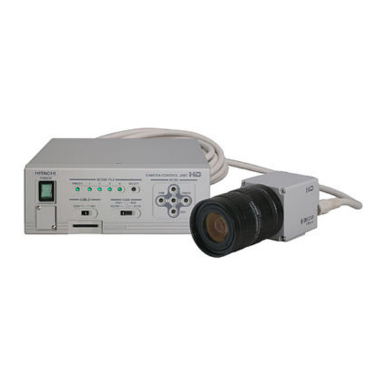
) ——————————————— 1 Operation Manual ———————————————————————————————————————————————————————————————————————— 1 Part code Overview The Hitachi color camera HV-HD201 is 3CCD 1080i/59.94, 1080i/50, 720p/59.94, 720p/50, it HDTV camera combining high picture quality provides the VBS and RGB/YPbPr analog signal and high stability with the convenience of C output of 480i/59.94(NTSC) and 576i/50(PAL) -
Page 16: Features
Features C mount Bi-directional data communication The camera uses a C mount lens, which is the de The camera can be connected to a personal facto standard in the industry. It allows use with computer RS-232C two-way data communications to provide finely detailed camera different types of optical systems. -
Page 17: Notes To Users
Consult do not enter the camera interior. These may a Hitachi Kokusai Electric dealer for a selection lead to failure or accident. of fine lenses according to the application. Do not modify the camera or use the camera with Installation and storage sites external covers removed. - Page 18 Cleaning A photographer’s blower or lens brush can be Blinking Screen at AUTO BLACK used for clearing dust from the lens and optical It is not abnormal operation through the screen filters. might blinks at the power start up or execution of Wipe dust from the case with a soft dry cloth.
-
Page 19: Name And Function Of Each Section
Name and function of each section... - Page 20 It sets the operational mode of HDTV. Please change it at power off state.) Please change it at power off state.) Outputs HD-SDI signal. Outputs Y/C signal. Outputs VBS signal. Inputs SYNC signal of HDTV for external synchronization. O u t p u t s t h e a n a l o g p i c t u r e Used for connection with the remote signal/synchronization signal.
-
Page 21: Lens
(see page 45). Also, as the lens iris approaches fully open, problems such as loss of resolution, shading Note: The HV-HD201 uses lens connector wiring and flare (overall image "white-out") can prescribed by the EIAJ (Electronic Industries detract from picture quality. -
Page 22: Flange Back Adjustment
3) Flangeback adjustment of zoom lens 1) Set the lens to telephoto and pickup an image more than 3 meters distant. Turn the focus ring to adjust the focus. 2) Set the lens to wide angle and while taking care not to disturb the focus ring, turn the flangeback adjustment ring to adjust the focus. -
Page 23: Video Signal Type Lens Adjustment
Video signal type lens adjustment Adjustment is required after replacing the lens or Change to the Lens screen and check the LENS if using the camera for the first time. TYPE setting. If DC, change this to Video. (1) Set the lens ALC control fully toward the 1) Preparation (1) If GAIN SW of camera is at AGC. -
Page 24: System Configuration Example
System configuration example HD-TV monitor HD-SDI SD-TV monitor AC adapter IA-60a Camera control box Video capturing/Control RC-Z3 Frame grabber board Pb/B Pr/R 232C... -
Page 25: Menu Screen Operation
Menu Screen Operation 1. Menu Structure For settings in the camera, the MAIN and SPECIAL SET menus are available. 1) MAIN Menu Structure Press the MENU button and MAIN MENU appears on the screen to indicate the main menu mode. Again press the MENU button to extinguish the menu and to enter in the direct mode. - Page 26 2) SPECIAL SET Menu Structure If the menu is not displayed, press the MENU button for 2 seconds while holding down the U button. Thus, the SPECIAL SET menu will be displayed. The SPECIAL SET menu indicates a list of items, and subsidiary menus are available for each special item.
- Page 27 DETAIL [ FILE1 ] COLOR DETAIL [ FILE1 ] DETAIL LEVEL COLOR DETAIL :OFF DETAIL FREQ. :MIDDLE HIGH CHROMA :OFF CH1 A.PHASE :[PUSH R] 1SEC LEVEL DEPENDENT:-110 PHASE 0 Ye-R CRISP :-110 WIDTH SOFT DETAIL W. :-118 LEVEL :-128 SOFT DETAIL B. :-118 H/V BALANCE CH2 A.PHASE :[PUSH R] 1SEC...
-
Page 28: Main Menu
2. MAIN MENU 1) CAMERA MODE : Camera mode • MANUAL : Nearly all function modes can be set. It is used for detailed settings. AUTO : Video level and white balance are automatic and a standard picture can be observed •... - Page 29 2) WHITE BALANCE : White balance mode The hue(white balance) of the camera image is adjusted that changes with the various illuminations. When white subject is captured, the hue is adjusted for the camera image to be white. PRST 3200K : The white balance condition is optimized at a color temperature of 3200K.
-
Page 30: Gain/Shutter
7) ALC : Change to ALC menu. 8) AUTO SETUP : Change to AUTO SETUP menu. 9) FILE SELECT : Select among scene files 1, 2, 3, and 4. The most suitable camera setting for a scene can be stored in each scene file and can be selected from these scene files. - Page 31 2) SHUTTER : Electronic shutter mode Shutter adjusts the light receiving time of CCD. It is used to adjust too bright subject and to reduce the after-image of the moving object. Using SHUTTER makes the image darker. Note: If a blinking light source such as a fluorescent lamp is used, flicker occurs. The inverter fluorescent lamps of high blinking frequency are not like to give influence although the flicker occurs in case of inverter fluorescent lamps which include low blinking frequency components.
- Page 32 immunity to flicker by setting 1/100 as the slowest allowable shutter speed for AES. If a value larger than 1/100 is set as the slowest allowable shutter speed, SHUTTER is turned off unless the amount of light into the camera is excessively high. AES OFFSET : ON [59.94Hz mode] 1/100 to 1/10087s AES OFFSET : ON [50Hz mode]...
-
Page 33: Detail
4. DETAIL: : : : DETAIL level setup Contours of the subject are emphasized to make the image easier to see. DETAIL [ FILE1 ] 1) DETAIL LEVEL : Setting of contour correction amount The DETAIL level can be set to in a range of -128 to 127.The degree of DETAIL LEVEL contour correction increases in the positive value setting, and it DETAIL FREQ. - Page 34 5. ALC ALC is for brightness control functions Auto Iris, AGC and AES. [ FILE1 ] 1) OVER RIDE : Auto iris level setting OVER RIDE ALC level setting in range of -128 to 127 (about ±2 F stops). SPEED :STANDARD Press R and L for respectively higher or lower video level PEAK/AVE...
- Page 35 5) GATE SELECT : ALC gate area setting. (It is displayed only for ALC GATE : ON) User can select pattern arbitrarily from MANUAL mode along with fixed 6 patterns from Mode 1 to Mode 6. Detected Area PATTERN 1 PATTERN 2 PATTERN 3 PATTERN 4...
- Page 36 6) MANU GATE EDIT : Manual ALC gate pattern setting (It is displayed only for ALC GATE : ON and GATE SELECT : MANUAL) Move the cursor to MANU GATE EDIT:[PUSH R] of ALC Menu. Press “R” button on the camera’s front face to ALC gate edit mode.
-
Page 37: Auto Setup
6. AUTO SETUP Menu for initial image adjustment AUTO SETUP 1) AUTO WHITE : Automatically adjust the white balance. Move the cursor to AUTO WHITE and press and “R” button for 1 AUTO WHITE :[PUSH R] 1SEC AUTO BLACK :[PUSH R] 1SEC second or more for automatic white balance adjustment. -
Page 38: Special Set
7. SPECIAL SET SPECIAL SET menu allows more detailed settings for the camera. menu allows more detailed settings for the camera. menu allows more detailed settings for the camera. menu allows more detailed settings for the camera. (Please refer to Page 12 for the display method of the SPECIAL SET menu.) 1) FILE SET : Change to FILE SET menu SPECIAL SET File operations, such as copy settings between scene files. -
Page 39: File Set
10) OTHER FUNCTION : Change to OTHER FUNCTION menu Sets saturated portion color correction, flare correction, and noise reduction. 11) TIME/DATE : Change to TIME/DATE menu. The calendar of the camera is matched to time. 8. FILE SET Used for transferring scene file data to another file or setting all data to preset values, and also the setting information can be saved to SD card an FILE SET read back. -
Page 40: File Name Set
9. FILE NAME SET FILE1 to FILE4 can be changed to user defined name. <How to set scene file name> When the cursor is at FILE1~4, press the R button. The first character of the setting data blinks in edit mode. FILE NAME SET Use L, R, U and D buttons to select an input character from the FILE1 : FILE1... - Page 41 10. SD CARD (It is display It is display It is display It is displayed only when the SD card has been inserted. ed only when the SD card has been inserted. ed only when the SD card has been inserted. ed only when the SD card has been inserted.) 1) MEMORY NO.
-
Page 42: Level
11. LEVEL The hue in dark and bright part of the red and blue image signal is adjusted. 1) ENABLE : Level control ON/OFF setting. Note : ENABLE is fixed at OFF for CAMERA MODE : AUTO. LEVEL [ FILE1 ] ENABLE :OFF 2) R GAIN : Sets bright part of red... -
Page 43: Masking
12. MASKING Menu for tone adjustment of selected color. There are 6/12 vector [HUE] and [SAT] masking for correction of hue and saturation and [LINEAR] masking for correction of hue while keeping picture brightness fixed. MASKING [ FILE1 ] The HUE/SAT is adjusted for Red(R), Green(G), Blue(B), Yellow(Y), [HUE][SAT] [LINEAR] Cyan(C) and Magenta(M) in 6 color mode and for natural tint of those 0 R-G: 0... - Page 44 : Changes chroma of red color. 13) R SAT 14) Y-R SAT : Changes chroma of natural tint of red and yellow. : Changes chroma of yellow color. 15) Y SAT 16) G-Y SAT : Changes chroma of natural tint of green and yellow. : Changes chroma of green color.
- Page 45 25) RG LINEAR : Color density and hue are changed in the direction of red-cyan axis. Blue and yellow do not change. 26) RB LINEAR : Color density and hue are changed in the direction of red-cyan axis. Green and magenta do not change.
- Page 46 The following diagrams illustrate linear masking(LINEAR) operations. RG LINEAR GB LINEAR BR LINEAR RB LINEAR GR LINEAR BG LINEAR...
-
Page 47: Gamma/Knee
13. GAMMA/KNEE Menu for gamma correction and knee(compression of bright part)correction. 1) GAMMA : Gamma ON/OFF • OFF : Gamma correction will not effective. GAMMA/KNEE [FILE1 ] • ON : Gamma correction will be effective. (Usual usage) GAMMA ON is selected unconditionally for CAMERA MODE: AUTO). GAMMA TABLE :STANDARD TOTAL GAMMA... - Page 48 6) KNEE : Sets operation mode of knee correction. KNEE correction is a function that compresses the high luminance part and makes the image difficult to saturate even for bright subjects. • OFF : KNEE correction is not operated. • ON : It provides natural gradation in bright portions.
-
Page 49: Detail
14. DETAIL Various settings of contour correction. DETAIL [ FILE1 ] 1) DETAIL LEVEL : Setting of contour correction amount DETAIL LEVEL The DETAIL level can be set to in a range of -128 to 127.The degree of DETAIL FREQ. :MIDDLE HIGH CHROMA :OFF... - Page 50 5) CRISP : Crispness level setting Minute noise is prevented being emphasized in the detail correction. The detail signal less than a fixed level is not corrected and detail correction becomes ineffective. Press the R button to increase the setting level and effect. Press the L button to decrease the setting level and reduce effect.
-
Page 51: Color Detail
15. COLOR DETAIL The amount of an The amount of an The amount of an The amount of an contour enhancement contour enhancement contour enhancement contour enhancement can be set can be set can be set can be set in the specified in the specified in the specified in the specified... -
Page 52: Auto White
16. AUTO WHITE Detailed setting concerning white balance correction. AUTO WHITE [FILE1 ] SPEED :STANDARD 1) SPEED : Sets real-time auto white balance response speed. HIGH LIMIT :10000K Standard : Usual setting • LOW LIMIT : 2500K Slow : Sets slow convergence speed. •... - Page 53 4) WHITE GATE : Sets the gate to adjust the white balance for a part of the screen as a subject. The best balance at the time of real time white balance operation can be controlled by matching the gate to white and gray in the screen.
-
Page 54: System
17. SYSTEM Menu for settings of image output mode, an external synchronization, and camera control communication. (The external synchronization of this camera is only for HD TV.) 1) ANALOG OUT SEL: : : : Sets analog signal output mode. SYSTEM HD TV : Outputs the analog output signal in HDTV mode. - Page 55 4) SYNC/HDVD SEL : Selects external synchronizing signal. (Sync in/out is according to state of EXT. SYNC switch.) ① To synchronize this camera with the synchronizing signal of other HD-TV device.( EXT. SYNC switch is set to IN.) SYNC IN : External synchronization with HD-TV sync signal(input from the SYNC IN •...
- Page 56 7) REMOTE : Sets the remote control baud rate. Selects from 9600bps and 19200bps. (When RS-232C/RC-Z3 switch is at RC-Z3, it allows 9600bps only) 8) MESSAGE RTN : Message display ON/OFF ON : Displays the result of AWB execution in the DIRECT mode. •...
-
Page 57: Id/Title
18. ID/TITLE ID and title display position and data setting menu. ID/TITLE 1) ID : ID display position setting :OFF Once an ID is assigned, it becomes possible to control a particular TITLE :OFF DATA SET camera unit remotely from a personal computer according to its That is, multiple camera units can be remote-controlled individually from one persona computer. - Page 58 <ID/TITLE Setup Procedure> When the cursor is at ID or TITLE, press the R button. DATA SET The first character of the setting data blinks in edit mode. Use L, R, U and D buttons to select an input character from the : ___ TITLE character table.
-
Page 59: Lens
19. LENS Menu for setting the lens functions 1) LENS Type : Sets type of auto iris. LENS : Iris opens in proportion to a DC control voltage. Also set to • LENS TYPE :VIDEO DC when not using an automatic iris. * IRIS MODE :--- * IRIS SPEED... - Page 60 5) CLOSE LIMIT : Sets close limit. (Effective only for DC Lens Type.) Sets the edge of close side of the lens controlled by auto iris. It just aligns it according to specification of lens. Observe the iris and adjust to precisely the largest value (smallest diameter). The setting range is from 0 to 8.0V.
-
Page 61: Other Function
20. OTHER FUNCTION 1) DYNAMIC CHROMA : Dynamic chroma ON/OFF setting OTHER FUNCTION OFF : Dynamic chroma function becomes ineffective. • DYNAMIC CHROMA:OFF ON : Improves coloration in bright scene components. • FLARE 2) DNR : Digital noise reduction setting R FLARE G FLARE The noise in the image is reduced. -
Page 62: Time/Date
21. TIME/DATE Menu for setting the internal clock of the camera. TIME/DATE 1) YEAR : : : : Sets year [2009-01-18. 13:42:36 ] YEAR :2009 MONTH 2) MONTH : Sets month DATE HOUR : 13 MINUTE : 42 3) DATE : Sets date 4) HOUR : Sets hour 5) MINITUTE :... -
Page 63: How To Attain Better Images
・Carry out AUTO BLACK again. If this message appears in repeated attempts, it is necessary to inspect the inside of the camera. In this case, contact your local Hitachi Kokusai Electric sales dealer or Hitachi Kokusai Electric service center. -
Page 64: White Balance Adjustment
White Balance Adjustment (WHITE BALANCE:MEMORY) Carry out white balance adjustment when the illumination condition (color temperature) is changed. Adjust the white balance when using the camera for the first time or after replacing the lens. 1. In the MENU mode, set WHITE BALANCE to MEMORY. 2. - Page 65 Error message Procedure AUTO WHITE:NG ・ Turn off the color bar. CHANGE TO CAMERA TRY AGAIN AUTO WHITE:NG ・ Set WHITE BALANCE: MEMORY CHANGE WHITE BALANCE TO MEMORY TRY AGAIN AUTO WHITE:NG ・ White balance cannot be made due to insufficient illumination. LOW LIGHT ・...
-
Page 66: Real Time Auto White
Realtime Auto White (WHITE BALANCE:AUTO) The camera detects a white part in the image by itself, and its internal microcomputer automatically adjusts white balance in realtime. Use this function in case that the color temperature varies with time (e.g., from morning to day to night). 1. -
Page 67: Auto Shading Correction
Auto Shading Correction Color shading may occur in the vertical direction on screen due to any characteristic of lens. This camera is equipped with a function for correcting color shading automatically. 1. Provide a proper aperture value of lens using the auto iris function or manually. 2. -
Page 68: Alc (Auto Level Control)
In combination of GAIN:AGC, SHUTTER:AES and AUTO IRIS, the following four kinds of ALC (auto level control) can be performed. This feature ensures stable video signal output according to a wide-range change in illumination. -
Page 69: Rc-Z3 Remote Control Panel
RC-Z3 Remote Control Panel All camera menu items can be operated remotely by connecting the RC-Z3 Remote Control Panel. Set camera’s rear panel switch RS-232C/RC-Z3 to RC-Z3 to connect the remote control panel. Operation (1) Direct control The following items can be controlled directly as well as from the control panel. ・BAR/CAM ・ENABLE(ON/OFF) ・M.BLK... -
Page 70: Rc-Z3 Panel Facilities
1. RC-Z3 panel facilities 15 TALLY/CALL button 16 SHUTTER button 17 CONTRAST button CAMERA CONTROL PANEL RC-Z3 18 ULTRA GAIN button ULTRA A.WHT CONTROL TALLY/CALL SHUTTER CONTRAST CONTROL switch GAIN ULTRA A.WHT button LOCK EXTENDER A.BLK FUNCTION A.BLK button EXTENDER BAR/CAM switch HIGH AUTO... - Page 71 ・OFF (green LED): Operation inhibited from RC-Z3. Operate from camera controls and switches. 2 2 2 2 EXTENDER LED This Extender LED is always extinguished using with the HV-HD201 camera. 3 3 3 3 BAR/CAM switch Selects the camera output signal.
- Page 72 (1) File selection Press the following buttons to change the camera and RC-Z3 settings. ・PRESET: : : : Produces the standard setting mode ・SCENE FILE 1: : : : FILE-1 (scene file 1) setting mode ・SCENE FILE 2: : : : FILE-2 setting mode ・SCENE FILE 3: : : : FILE-3 setting mode ・SCENE FILE 4: : : : FILE-4 setting mode Note: The pressed SCENE FILE button lights, then flashes when the application file data are changed.
- Page 73 ・ ・ ・ ・ OFF: Adjustments are ineffective when the ENABLE button is extinguished. Note: When CAM MODE AUTO, the ENABLE button is ineffective. 15 15 15 15 TALLY/CALL button TALLY/CALL button lights when pressed. However, function is ineffective in the HV-HD201 camera.
- Page 74 ・ REMOTE: Iris is adjusted by the iris control ・ MANUAL: Set the lens A/M switch to M and adjust the lens iris ring manually. Note: When using the video type lens, REMOTE and MANUAL function is ineffective in the HV-HD201 camera.
- Page 75 23 23 23 23 GAIN switch Sets the camera sensitivity. Press the switch upward to select the sensitivity in the sequence 0→3→6→9→12 dB→18 dB. The sensitivity setting is indicated by the combined GAIN LED indication. Note: When CAMERA MODE AUTO or AGC ON,the -3dB GAIN LED indicated all the time. 24 24 24 24 WHITE BALANCE mode select switch The white balance mode can be selected in the sequence PRESET →...
-
Page 76: Menu Screen Composition
IRIS control 26 26 26 26 Adjusts the lens iris as follows. ・ AUTO : OVER-RIDE (fine adjustment about ±2 F-stops) can be adjusted ・ REMOTE: Adjustable in the range from fully open to fully closed ・ MANUAL: Iris is not adjustable from the RC-Z3 (adjust by manually turning the lens iris ring). M. -
Page 77: Connectors
Connectors MULTI connector (DMSH-15S) Pin No. Signal designation PLAG : Housing KEC-15P R/R-Y OUT Pin contact JK-SP2140 G/Y OUT Cover JK-C151C B/B-Y * Use No.4-40UNC plug retaining screws. UNREG +12V IN HD IN/HD OUT/ SYNC OUT VD IN/GL IN /VD OUT *TXD/RXD and the REMOTE connector can not be used simultaneously. - Page 78 REMOTE connector (HR10A-7R-4S) LENS connector (D4-151N-100) Pin No. Signal Pin No. Signal +12V output +12V RXD/SD input TXD/SD output Control Plug: HR10A-7P-4P Plug: E4-191J-100...
- Page 79 Y/C connector(TCS-7547-01-401) DC 12V IN connector(RMI12BRD-3PH) Pin No. Signal Pin No. Signal Y GND 1 +12V input C GND 2 Y output 3 C output...
-
Page 80: External Synchronization
External synchronization HV-HD201 inputs or outputs the external synchronizing signal of HDTV and can synchronize video and other similar cameras. when the synchronization signal is input(or output), set the camera menu and EXT. SYNC switch of the camera back panel referring to the table below in advance. -
Page 81: Specifications
Specifications 1) Mode HDTV modes 1080/59.94i, 1080/50i, 720/59.94p, 720/50p SDTV modes(Analog output only) 480/59.94i, 576/50i 2) Image sensor 1/2-size CCD image sensor (Image size : 1/2-size) Total pixels 1504(H) × 1099(V) Effective pixels 1440(H) × 1080(V) Effective image area 6.98mm(H) × 3.92mm(V) 3) Imaging system R, G, B 3-CCD 4) Optical system... - Page 82 ARIB bar 18) Power supply voltage 12 V DC rating (10.5V~15V) 19) Power consumption Approx. 22 W(HV-HD201), Approx. 25 W(HV-HD201M) 20) Dimensions HEAD : 50mm(W) x 50mm(H) x 55mm(D) (excluding lens) CCU : 188mm(W) x 75mm(H) x 180mm(D) 21) Mass HEAD : Approx.
-
Page 83: Input/Output Signals
Input/Output Signals 1. Input signals 1) Synchronization signal input HDTV Tri-level SYNC : 0.3 Vp-p ±0.1Vp-p (SYNC IN connector) HDTV HD/VD : 2 to 5 Vp-p (MULTI connector) Note: External synchronization is possible only with HDTV signal same as video output. It is effective only when the EXT. - Page 84 4) Composite Video Output (VIDEO Connector) VBS 1.0 Vp-p/75 5) Y/C Output (S-VIDEO Connector) Y: 1.0 Vp-p/75 C: NTSC 0.286 Vp-p (Burst)/75 PAL 0.3 Vp-p (Burst)/75 6) HDMI Output (HD OUT Connector) : Only HV-HD201M) 7) Synchronization signal output (MULTI connector) HDTV 3 value SYNC : 0.3 Vp-p/75 HDTV HD/VD : 2 Vp-p/75...
Need help?
Do you have a question about the HV-HD201 and is the answer not in the manual?
Questions and answers