
Related Manuals for Hitachi HV-C20


Summary of Contents for Hitachi HV-C20
- Page 1 3-CCD Color Camera MODEL HV-C20/C20M OPERATION MANUAL Please read this operation manual carefully for proper operation, and keep it for future reference. Hitachi Denshi , Ltd.
- Page 2 PC, the camera can be controlled appropriately. As an 1D number can be registered to each camera, plural cameras can be controlled from a single PC. Variation HV-C20: Standard camera, DC type. HV-C20M. For optical instrumentation system, DC type. Standard composition Camera, HV-C20...
- Page 3 If the camera should show any abnormality, be sure to turn off the camera and disconnect the power cord, then contact your nearest Hitachi Denshi service station. Operating considerations Supply voltage Check that the supply voltage is between 10.5V and 17V DC.
- Page 4 Phenomena inherent to CCD Following are the phenomena inherent to a CCD imaging device, and not 1) Smear and When strong light (lamp, fluorescent lamp, reflected light, etc.) is shot, pale bands are displayed vertically above and below the light. In this case, change the angle of the camera so that such strong light does not enter the camera through the lens.
- Page 5 4.2mm or less Lens Caution Observe the dimensions of the lens mounting section as illustrated at the right. Lens If the dimensions are not observed, do not Ø18 mm such a lens, because the lens and the camera will be damaged. Flange surface of a lens Selection...
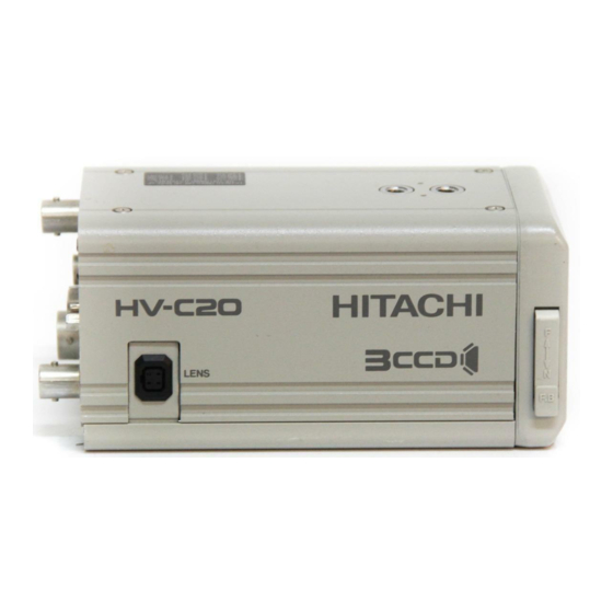
- Page 6 HV-C20/20M Name and function of each section Tapped Camera Mount hole Flange focal distance adjustment ring Lens Connector Tapped Camera Mount hole Pilot lamp BAR/SEL switch Direct mode: Operate as the ON/OFF switch of the color bar signals. MENU mode: Operate as a cursor shift key to select each function.
-
Page 7: Specifications
Specifications Color format NTSC/PAL Optical system 1/2 , f1.6 prism Optics Imaging system RGB, 3 CCD s Imaging device 1/2" CCD No. of total pixels NTSC: 811(H) X 508(V) PAL: 795(H) X 596(V) No. of effective pixels NTSC: 768(H) X 494(V) PAL: 752(H) X 508(V) Sensing area 7.95(H) x 6.45(V)mm Sync system... - Page 8 Menu screens operation 1. Configuration The camera settings can be changed by corresponding menu screen. Pressing the MENU switch establishes the menu mode, and the menu screen is paper on video. Another pressing the MENU switch establishes the direct mode (normal operation mode). menu screen contains...
-
Page 9: Main Menu
2. MAIN MENU CAMERA MODE: Camera mode MENU mode Almost all function modes can be set. Select the MANU mode to perform the camera setting precisely AUTO mode The full auto mode is established. the functions with * are fixed to the respective values, and the cursor skips these functions. - Page 10 AGC : AGC ON/OFF ON mode Gain is automatically controlled. The upper limit of gain is the value set by the LIMIT on the next line. OFF mode Gain is fixed to the value set by the GAIN on the next line. LIMIT: Upper limit value of AGC (in the AGC:ON mode).
- Page 11 EXT TRIG mode: Only exposure time can be controlled by inputting one pulse. SYNC is not reset. NOTE: For the use of the Field-On-Demand function, contact your local Hitachi Denshi sales representative for more detail information’s.. DTL: DTL amount control...
- Page 12 Set to either of these baud rates when a PC is used. For the PC control protocol and Data Command are needed please contact your nearest Hitachi Denshi sales representative. ID/TITLE: The ID/TITLE menu is executed. RETURN: The MAIN MENU is displayed.
- Page 13 6. IRIS GATE GATE: Iris gate ON/OFF ON mode The AGC, lens iris and auto electronic shutter are controlled by detecting the video signal level at the set window section. As the window signal is superimposed on the video signal in the menu mode, the optimum window signal can be set by changing the size and position of the gate area, while observing the monitor.
- Page 14 7. LENS TYPE: Setting of kind of auto iris DC mode Select the DC mode when a lens whose iris is controlled in proportion to the DC voltage is used. Select the DC mode when the auto iris lens is not used. VIDEO Select the VIDEO mode when a lens whose iris is controlled by the video signal is used.
- Page 15 9. ID/TITLE ID: Setting of ID No. display position When ID number is registered to each camera, the desired camera can be remotely controlled from the a PC. The data on the next line is executed. This ID number can be displayed on the screen. TITLE : Displayed at the top right BOTTOM : Displayed at the bottom right...
- Page 16 Adjustment for better White balance adjustment Adjust the white balance when illumination conditions are changed. Set WHT BAL to MEM in the menu mode. Select the direct mode. Adjust the lens iris appropriately. Place a white thing in the scene and zoom in. Press the AWB switch.
- Page 17 Auto shading correction Uneveness in colors may be observed in the vertical direction according to a lens. This camera is provided with the function to correct such uneveness in colors automatically. Two correction modes available. Prior execution correction, select desired correction mode in the menu mode.
- Page 18 Three kinds of the automatic level control (ALC) functions are available by the combination of the AGC:ON mode, SHUTTER:AES mode and AUTO IRIS. Therefore, a stable video output signal is available for the wide change in quantity of light. Note 1. The AES function is not available for a lens of VIDEO type. 2.
- Page 19 SD input SD output 12V IN Connector Pin # Signal +12V output LENS Connector LENS Connector Canon PH10x8.5P RGE Pin # Signal Pin # Signal Control Power +12V Video Dimensions HV-C20/HV-C20M (TOP) 2-1/4" UNC(Depth :7) HV-C20 HITACHI 3 CCD (Bottom)
Need help?
Do you have a question about the HV-C20 and is the answer not in the manual?
Questions and answers