Table of Contents
Advertisement
Quick Links
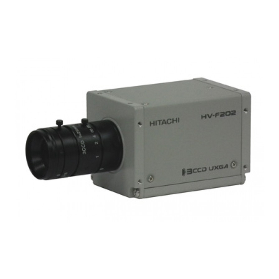
High pixel 3CCD camera
HV-F202SCL
Operation Manual
Thank you for purchase this fine Hitachi Kokusai Electric CCD camera.
Before using the camera, please read this operation manual carefully.
There is a possibility that the revised edition is exhibited on web.
Please confirm by web shown in an Installation Guide.
Hitachi Kokusai Electric Inc.
RoHS Compliant
These products comply with the requirement of the RoHS (Restriction of the
use of Certain Hazardous Substances in Electrical and electronic Equipment)
Directive 2002/95/EC.
Version in March, 2014
Advertisement
Table of Contents

Related Manuals for Hitachi HV-F202SCL


Summary of Contents for Hitachi HV-F202SCL
- Page 1 High pixel 3CCD camera HV-F202SCL Operation Manual Thank you for purchase this fine Hitachi Kokusai Electric CCD camera. Before using the camera, please read this operation manual carefully. There is a possibility that the revised edition is exhibited on web.
-
Page 2: Important Safety Instructions
IMPORTANT SAFETY INSTRUCTIONS 1. Read Instructions All the safety and operating instructions should be read before the product is operated. 2. Retain Instructions The safety and operating instructions should be retained for future reference. 3. Heed Warnings All warnings on the product and the operating instructions should be adhered to. 4. - Page 3 16. Object and Liquid Entry Never push objects of any kind into this product through openings as they may touch dangerous voltage points or short-out parts that could result in a fire or electric shock. Never spill liquid of any kind on the product. 17.
- Page 4 WICHTIGE SICHERHEITS ANWEISUNGEN 1. Alle Anweisungen lesen Vor Betrieb des Erzeugnisses sollten alle Sicherheits-und Bedienungsanleitungen gelesen werden. 2. Die Anweisungen aufbewahren Die Sicherheits-und Bedienungsanleitungen sollten fünftigen Bezug aufbewahrt werden. 3. Warnungen beachten Die Warnungen auf dem Erzeugnis und in den Bedienungsanleitungen solten beachtet werden. 4.
- Page 5 16. Eindringen von Fremdkörpern und Flüssigkeit Niemals Objekte irgendwelcher Art durch die Öffnungen in das Gerät schieben, da diese unter hoher Spannung stehende Teile berühren oder kurzschließen können, wodurch es zu Feuer oder elektrischem Schlag kommen kann. Niemals Flüssigkeiten irgendwelcher Art auf das Erzeugnis verschütten. 17.
- Page 6 MISES EN GARDE IMPORTANTES 1. Lire les instructions Lire toutes les instructions de sécurité et de fonctionnement avant de faire fonctionner l’appareil. 2. Conserver ces instructions Conserver les instructions de sécurité et de fonctionnement á des fins de référence ultérieure. 3.
- Page 7 16. Pénétration d’objets et de liquides Ne jamais enfoncer d’objets d’aucune sorte dans les ouvertures de l’appareil car ils pourraient toucher des points de tension dangereuse ou court-circuiter des piéces, ce qui pourrait provoquer un feu ou un choc électrique. Ne jamais renverser de liquide d’aucune sorte sur l’appareil.
-
Page 8: Important Notice
WARNING Changes or modifications not expressly approved by Hitachi Kokusai Electric Ltd. responsible for compliance could void the user’s authority to... - Page 9 This page show the declaration of conformity for CE. That reference number is the KV-0366, and report number is the V3T-0164. Note : This product using the following equipment satisfied the CE standard. The camera cable by shield type (C-201KSS). Mini-CameraLink cable (C-201SCL).
- Page 10 China RoHS The following statement is related to the regulation on “ Measures for the Administration of the control of Pollution by Electronic Information Products “ , known as “ China RoHS “. The table shows contained Hazardous Substances in this camera. 说明书(环境方面:补充资料)...
- Page 11 Phenomena inherent to CCD imaging device The following phenomena are inherent to a charge coupled device imaging element and do not indicate malfunction. 1) Smear and blooming Vertical bands are visible when a strong light enters the scene. Adjust the camera aiming direction carefully to avoid strong direct or reflected light.
- Page 12 ・ Sop using the camera at the approach of electrical storm (thunder audible). Protect the camera from rain if using it outdoors. ・ In event the camera shows any abnormality, switch off the camera and disconnect the power cord. Contract a Hitachi Denshi service representative. 2. Handling ・ Do not attempt to remove cover.
-
Page 13: Table Of Contents
Table of Contents 1. Overview ······················································································································ 1. 2. Standard Composition ····································································································· 1 3. Features ······················································································································· 1 4. System example ············································································································ 1 5. Section name and functions ····························································································· 2 6. Camera mounting ··········································································································· 2 7. Lens ···························································································································· 2 8. Connector ····················································································································· 3 9. -
Page 14: Overview
Overview HV-F202SCL is high precision 3CCD progressive scan color camera, which has single chip digital processing LSI, a C mount prism, 1/1.8 inch 2,000,000 pixels square CCD and CameraLink interface. Standard composition Check when unpacking Camera ········································································································ 1 Installation guide ····················································································· 1 Plug for DC IN/SYNC connector (HR10A-10P-12S) ·············... -
Page 15: Section Name And Functions
Section name and functions Camera / Tripod adaptor mounting screw holes DC IN/SYNC connector Use for DC+12V power or external trigger / VD signal input or Flash / Lens mount VD output (C mount) DC IN/SYNC D.OUT 1 D.OUT 2 MODEL... -
Page 16: Connector
Connector 1. CameraLink connector (a) Interrelation between number of DATA bit and number of used conndecor Number of Data bits D.OUT1 D.OUT2 24bit (R: 8bit G: 8bit B: 8bit) O: Use 30bit (R: 10bit G: 10bit B: 10bit) -: Not use 36bit (R: 12bit G: 12bit B: 12bit) (b) Signal connection of DIGITAL OUT connector D.OUT2... - Page 17 2. DCIN/SYNC connector PIN NO. Signal PIN NO. Signal GND (+12V) TRIG-A / VD (H) IN +12V TRIG-B (C) IN TRIG-B (H) IN N.C. FLASH / VD (H) OUT FLASH / VD (C) OUT N.C. N.C. TRIG-A / VD (C) IN Connector (camera side) : SANWOO SHN-10-12 (RPCB) or equivalent Plug (matching cable plug : HR10A-10P-12S(01) HIROSE or equivalent TRIG-A/VD and TRIG-B are input using digital isolation, and FLASH/VD OUT is output by digital Isolation,...
-
Page 18: Functions And Operations
Functions and operations Various mode setup and adjustment of HV-F202SCL are performed by the remote control via CameraLink. Operation and adjustment way of function utilized are described below. See "Remote control" (page 10 to 16) and "Command list" (page 17 to 20) about communication method of each command. - Page 19 (3) GAIN LEVEL : Setting of electrical sensitivity -LEVEL- : Adjust MANUAL gain level 0 (Factory setting) to 341 : Set MANUAL gain when AGC is OFF. Adjustable from 0 to 12dB in 342 steps. (4) BRIGHTNESS : Adjust offset level 0 to 255 : Set in 256 steps.
- Page 20 (10) WHITE BALANCE : Setting of white balance. -MODE- : Selection of mode : White balance is adjusted in real time (automatic tracking). MANUAL (Factory setting) : White balance is adjusted manually by adjusting R, G and B GAIN. ADJUST : State for automatic white balance adjustment.
- Page 21 -ADJUST- : AUTO SHADING (Correct white shading) ⅰ. Provide a proper aperture value of lens. ⅱ. Take an white image fully on screen. At this step, take care so that uneven brightness will not occur in the vertical and horizontal direction. ⅲ.
- Page 22 (20) MEMORY CHANNEL : Setting of memory channel -LOAD- : Load memory channel DEFAULT (Factory setting): Return to the factory setting.. MEMORY 1 to MEMORY 4 : Load the memory channel 1 to 4 -SAVE- : Save memory channel MEMORY 1 to MEMORY 4 : Save current settings to the memory channel 1 to 4...
-
Page 23: Remote Control
Remote control 1. Comms* specifications ・Control system : Start-stop synchronization system ・Transmission rate : 9600 bps ・Data length : 8 bit ・Star bit : 1 bit ・Stop bit : 1 bit ・Parity : None ・Bit transfer : LSB first *Comms: Communications 2. - Page 24 HITACH Transmit data (ASCII code) 3CCD ACK code (06H) Slave (HV-F202SCL) Master (Machine) ① Session starts when ENQ is sent from master to slave. ② Slave acknowledges by returning ACK to master. ③ Master sends data to slave. ④ Slave acknowledges receipt of data by again returning ACK to master and end the handshake.
- Page 25 NACK code (15H) 3CCD ENQ code (05H) Slave NACK code (15H) (HV-F202SCL) ENQ code (05H) Master (Machine) NACK code (15H) ① Master sends ENQ code to slave. ② Since ACK code cannot be sent, slave sent NACK code to master.
- Page 26 3 second elapse Send data (ASCII code) 3CCD 3 second Slave elapse (HV-F202SCL) Send data (ASCII code) Master (Machine) 3 second elapse Send data (ASCII code) ① Session starts when ENQ is sent from master to slave. ② Slave acknowledges by returning ACK to master.
- Page 27 ENQ code (05H) ACK code (06H) Read command (ASCII code) HITACH ACK code (06H) 3CCD Read data (ASCII code) Slave 3 second (HV-F202SCL) elapse Read data (ASCII code) Master (Machine) 3 second elapse Read data (ASCII code) 3 second elapse Read data (ASCII code) ①...
- Page 28 2 byte (ASCII code) Used for EEPROM write (0: write absent, 1: write present). ・ID No. : Camera peculiar ID. HV-F202SCL has (FFH). 2 byte (ASCII code) ・Area address : Classification of Send data (01H) and Read command (81H). 2 byte (ASCII code) ・Relative No.
- Page 29 (2) Read (receive) data (slave to master) (a) Command data are converted into ASCII code and transmitted. (b) Comms byte quantity is 10. (c) Comms data format (transmission sequence) E T X S U M S T X Text data 1 byte 6 byte 1 byte...
-
Page 30: Command List
Command list 1. Send data (setting command, Note: 1 to 7 and SUM need to be transformed into ASCII code) Item ETX SUM AREA RELATIVE STATUS ID NO. DATA ADDRESS FIXED MODE 1TRIG VD CONT TRIGGER POSITIVE POLARITY NEGATIVE CL-CC1 SOURCE 12pin 1/30... - Page 31 Item AREA RELATIVE STATUS ID NO. DATA ADDRESS MODE MANUAL AWC ADJUST (*1) WHITE MIN (0) BALANCE R-GAIN MAX (255) MIN (0) B-GAIN MAX (255) MODE MIN (0) R-SATURATION MAX (255) MIN (0) R-HUE MAX (255) MIN (0) Cy-SATURATION MAX (255) MIN (0) Cy-HUE MAX (255)
- Page 32 Item ETX SUM AREA RELATIVE STATUS ID NO. DATA ADDRESS VD/FVAL FVAL HD/LVAL LVAL 24bit DATA BIT 30bit 36bit SIGNAL FLASH OUT OUTPUT POSITIVE POLARITY NEGATIVE MODE WHITE SPOT MIN (0) THRESHOLD MAX (255) DETECT MIN (DEFAULT) LOAD CH 1 MEMORY MAX (CH 4) MIN (CH 1)
- Page 33 2. Read-out command (Note: 1 to 7 and SUM need to be transformed into ASCII code) Item AREA RELATIVE STATUS ID NO. DATA ADDRESS MODE TRIGGER SOURCE POLARITY PRESET SHUTTER SPEED VARIABLE VALUE GAIN LEVEL BRIGHTNESS MODE GAMMA LEVEL MODE KNEE POINT SLOPE...
-
Page 34: Cameralink Output Timing Chart
CameraLink output timing chart 1. Horizontal timing 1920 clk 1600 clk VIDEO Active Picture LVAL 100 clk 110 clk 110 clk 1clk = 13.889ns 2. Vertical timing 1252 H 1200 H Active Picture VIDE FVAL 37 H 1 H = 1920 clk = 26.667 us 12 H... - Page 35 3. Transmitter LVDS output pulse position measurement (1) Base Configuration (a) 24bit D.OUT 1 13.889ns (72.0000MHz) CLKX Previous Cycle Next Cycle R7-1 R6-1 N.U. B3-1 B2-1 N.U. FVAL LVAL (VD) (HD) G2-1 G1-1 R1-1 R0-1 N.U.: Not used When using at Base configuration, please be sure to connect CameraLink cable to D.OUT 1. If the cable is connected to D.OUT 2, machine may break down.
- Page 36 (2) Medium Configuration (a) 30bit D.OUT 1 13.889ns (72.0000MHz) CLKX Previous Cycle Next Cycle R7-1 R6-1 N.U. N.U. N.U. B3-1 B2-1 N.U. FVAL LVAL (VD) (HD) N.U. R9-1 N.U. N.U. R1-1 R0-1 N.U.: Not used D.OUT 2 13.889ns (72.0000MHz) CLKY Previous Cycle Next Cycle N.U.
- Page 37 (b) 36bit D.OUT 1 13.889ns (72.0000MHz) CLKX Previous Cycle Next Cycle R7-1 R6-1 N.U. B3-1 B2-1 N.U. FVAL LVAL (VD) (HD) R10-1 R9-1 R1-1 R0-1 N.U.: Not used D.OUT 2 13.889ns (72.0000MHz) CLKY Previous Cycle Next Cycle N.U. N.U. N.U. N.U.
-
Page 38: Trigger Operation And Timing Chart
Trigger operation and timing chart 1. Normal mode Shutter time (Camera setting value) Shutter time Data output 1252 H 12 H 37 H FVAL 1200 H 2. Fixed shutter mode When external trigger signal is POSITIVE (high active), after the trigger signal rise, exposure is start. The exposure time is set by the camera electronic shutter speed. - Page 39 3. ONE trigger mode When external trigger signal is POSITIVE (high active), after the trigger signal rise, exposure is start. At the trigger signal falling edge, the internal VD signal is reset and the video data are transmitted. The trigger signal width equals the exposure time.
-
Page 40: Input / Output Signal
Input / Output signal 1. Input signal The level of the trigger signal input to HV-F202SCL is as follows. (1) Input from CameraLink cable LVDS level. (2) Input from 12-pin connector 5Vp-p ± 0.5V 2. Output signal The level of the trigger signal output from HV-F202SCL is as follows. -
Page 41: Specifications
Specifications Specifications of HV-F202SCL are showing. Optical system 1/1.8-inch F1.8 prism with IR cut filter Imaging device 1/1.8-inch interline CCD Total pixels 1688 (H) x 1248 (V) Effective pixels 1628 (H) x 1236 (V) Active pixels 1600 (H) x 1200 (V) Pixel pitch 4.4μm (H) x 4.4μm (V) -
Page 42: Dimensions
Dimensions... - Page 43 14-1 Sotokanda 4-choume, Chiyoda-ku, Tokyo 101-8980, Japan Phone: +81(0)3-6734-9432, Fax: +81(0)3-5209-5942 URL: http://www.hitachi-kokusai.co.jp/global/ Hitachi Kokusai Electric (Shanghai) Co., Ltd. Beijing Branch : Room 1415, Beijing Fortune Building, 5 Dong San Huan Bei-Lu, Chao Yang District, Beijing, 100004 China Phone: +86(0) 10-6590-8755/8756, Fax: +86(0) 10-6590-8757 Hitachi...
Need help?
Do you have a question about the HV-F202SCL and is the answer not in the manual?
Questions and answers