Table of Contents
Advertisement
This Manual is Bookmarked
Operating Instructions and Parts Manual
Table Saw
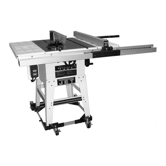
Model: JWTS-10JF
JWTS-10JF Table Saw shown with optional Mobile Base Stand
WMH TOOL GROUP
2420 Vantage Drive
Elgin, Illinois 60123
Part No. M-708301
Ph.: 800-274-6848
Revision H2 06/04
www.wmhtoolgroup.com
Copyright © WMH Tool Group
Advertisement
Table of Contents

Related Manuals for Jet JWTS-10JF


Summary of Contents for Jet JWTS-10JF
-
Page 1: Table Saw
This Manual is Bookmarked Operating Instructions and Parts Manual Table Saw Model: JWTS-10JF JWTS-10JF Table Saw shown with optional Mobile Base Stand WMH TOOL GROUP 2420 Vantage Drive Elgin, Illinois 60123 Part No. M-708301 Ph.: 800-274-6848 Revision H2 06/04 www.wmhtoolgroup.com... -
Page 2: More Information
This manual has been prepared for the owner and operators of a JWTS-10JF Table Saw. Its purpose, aside from machine operation, is to promote safety through the use of accepted correct operating and maintenance procedures. Completely read the safety and maintenance instructions before operating or servicing the machine. -
Page 3: Table Of Contents
Safety Devices ............................27 Feather Board............................27 Filler Piece............................... 28 Push Stick & Push Block ......................... 28 Maintenance..............................29 Cleaning ..............................29 Lubrication ............................... 29 Miscellaneous............................29 Troubleshooting ............................30 JWTS-10JF Table Saw Parts List ....................... 31 JWTS-10JF Exploded View ........................34... - Page 4 JETFENCE Parts List..........................36 JETFENCE Exploded View......................... 37 Stand Assembly Parts List and Exploded View ..................38 Ordering Replacement Parts........................40 The specifications in this manual are given as general information and are not binding. WMH Tool Group reserves the right to effect, at any time and without prior notice, changes or alterations to parts, fittings, and accessory equipment deemed necessary for any reason whatsoever.
-
Page 5: Warnings
Warnings 1. Read and understand the entire owners manual before attempting assembly or operation. 2. Read and understand the warnings posted on the machine and in this manual. Failure to comply with all of these warnings may cause serious injury. 3. - Page 6 21. Provide for adequate space surrounding work area and non-glare, overhead lighting. 22. Keep the floor around the machine clean and free of scrap material, oil and grease. 23. Keep visitors a safe distance from the work area. Keep children away. 24.
-
Page 7: Kickback Prevention
To safeguard your machine from unauthorized operation and to avoid accidental starting by young children, the use of a padlock is highly recommended. JET model BP-1 is available from your local authorized JET distributor or by calling JET Equipment & Tools at 800-274-6848. -
Page 8: Features
Features Specifications Model Number..........................JWTS-10JF Stock Number ............................. 708301 Blade Diameter ............................10" Arbor Diameter............................5/8" Maximum Depth of Cut ..........................3-1/8" Maximum Rip to Right of Blade .........................30" Maximum Rip to Left of Blade ........................12" Maximum Depth of Cut at 45°........................2-1/8" Table in Front of Saw (Max. Crosscut) ....................11-1/4"... -
Page 9: Definitions And Terminology
Definitions And Terminology Arbor: Metal shaft that connects the drive The blade guard and splitter must be re-installed mechanism to the blade. after performing a non-through cut to avoid accidental contact with the saw blade during Bevel Edge Cut: Tilt of the saw arbor and blade operation. -
Page 10: Contents Of The Shipping Cartons
Shipping Contents Read and understand the entire contents of this manual before attempting assembly or operation! Failure to comply may cause serious injury! Contents of the Shipping Cartons Tools Included for Assembly Table Saw Carton Arbor/Blade Guard Bracket Wrench 1 ea Table Saw Hex Wrench (3mm) 2 ea... -
Page 11: Unpacking And Cleanup
Assembly Read understand assembly instructions before attempting assembly! Failure to comply may cause serious injury! Unpacking and Cleanup 1. Finish removing all contents from the shipping carton. Keep the saw table upside down (Figure 1) and place on a two-by-four or similar piece of wood under the rear of the saw. -
Page 12: Assembling The Saw To The Stand
Turn the stand upside down and place onto the table saw (Figure 3) Note: The side with the JET logo is the front side of the stand and will be on the same side as the Warning label on the table saw. -
Page 13: Extension Wings
Extension Wings Referring to Figure 8: 1. Attach an extension wing (A) to the table (B) on the right side using three M10x20 hex cap screws (C), three M10 lock washers (D), and three M10 flat washers (E). Hand tighten only at this time. -
Page 14: Front Guide Rail
Front Guide Rail Required Fastening Hardware: A – 1 ea – Connecting Plate C – 2 ea – Socket Head Cap Screws (1/4) D – 2 ea – Lock Washer (1/4) E – 2 ea – Flat Washers (1/4) G – 4 ea – Flat Head Screws (5/16x1-1/4) H –... -
Page 15: Extension Wing Adjustment
Extension Wing Adjustment Referring to Figure 12: 1. Level each extension wing (A) to the saw table (B) by using a straight edge (C). Start by tightening the three screws on each extension wing that holds it to the table. Tighten these just enough to hold the wing in place but loose enough to change the wing height by tapping on it. -
Page 16: Installing The Blade
3. Line up the hole in the locating plate (A, Fig. 15) with the hole in the locating block (B, Fig. 15) and fasten the plate to the block with one M8 x 35 hex cap screw (C, Fig. 15) and one each M8 lock washer and flat washer (D, Fig. -
Page 17: Aligning The Blade Guard And Splitter
Aligning the Blade Guard and Splitter Referring to Figure 18: 1. Raise the blade guard away from the table and hold the anti-kick pawls (A) away from the table surface. A hex wrench (B) works perfect for this application. Using an accurate straight edge (C), align the splitter with the saw blade, if required, as follows: 2. -
Page 18: Motor And Guard Bracket
2. Remove the motor plate shaft (A, Fig. 21) from the motor bracket (B, Fig. 21). 3. Position the large slot on the motor plate under the motor bracket and raise the motor plate to align the holes for the motor plate shaft. The flat surface of the motor plate is on top. -
Page 19: Belt And Belt Cover
Belt and Belt Cover 1. Lower the saw blade completely. This makes it easier to position the v-belt on the arbor pulley. 2. Position the v-belt (A, Fig. 24) on the arbor pulley, lift up on the motor assembly, place the v-belt on the motor pulley (B, Fig. -
Page 20: Miter Gauge Operation
Miter Gauge Operation 1. Operate the miter gauge by loosening the lock knob (A, Fig. 27) and turning the miter body (B, Fig. 27) to the desired angle. To move the gauge beyond the index stops of 45º and 90º, flip down the stoplink (C, Fig. -
Page 21: Grounding Instructions
Electrical Connections prong grounding plugs and 3-pole receptacles that accept the tool's plug. The JWTS-10JF table saw is rated at 115/230V and comes from the factory prewired at 115V. Repair or replace damaged or worn cord The table saw comes with a plug designed for immediately. -
Page 22: Adjustments
Adjustments Blade Raising and Tilt Mechanism Never try to force the tilting mechanism past the 45º or 90º stops! This may cause the blade to go out of alignment! To raise or lower the saw blade, loosen the lock knob (A, Fig. 29) and turn the handwheel (B, Fig. 29) until the desired height is reached. -
Page 23: Wear Adjustment In Raising Mechanism
Wear Adjustment in Raising Mechanism To adjust for wear in the raising mechanism: 1. Disconnect the saw from the power source. 2. Remove the lock knob and raising handwheel but do not remove the pointer (Figure 33). 3. Loosen the lock nut (A, Fig. 33) using a 15/16" combination wrench. -
Page 24: Rip Sawing
Rip Sawing Ripping is where the work piece is fed with the grain into the saw blade using the fence as a guide and a positioning device to ensure the desired width of cut (Figure 36). Figure 34 Dull, badly set, improper, or improperly filed cutting tools and cutting tools with gum or resin adhering to them can cause accidents. -
Page 25: Resawing
on the front rail, or by measuring the distance When ripping long boards, use a support at the between the blade (B) and fence (A). Stand out front of the table, such as a roller stand, and a of line with the saw blade and workpiece to support or "tailman"... -
Page 26: Bevel And Miter Operations
Crosscutting should never be done freehand nor To improve the effectiveness of the miter gauge should the fence be used as an end stop unless in crosscutting, some users mount an auxiliary an auxiliary block is clamped to the front of the wooden extension face (with a glued-on strip of blade area such that the cutoff piece comes free sandpaper) to the miter gauge as shown in... -
Page 27: Safety Devices
Have the blade extend only 1/8" above the top of be utilized to keep operator's hands away from the workpiece. Exposing the blade above this the blade. Upon completion of the operation point can be hazardous. requiring removal of the guard, the entire guard assembly must be placed back on the machine in its proper working order. -
Page 28: Filler Piece
See the templates in Figures 49 and 50 for use of a push stick. construction details, or purchase one from the JET, Performax and Powermatic Woodworking Machinery and Accessories catalog. Figure 49 – Push Block Template Figure 48 – Filler Piece... -
Page 29: Maintenance
Always disconnect power to the machine before performing maintenance. Failure to do this may result in serious personal injury. Cleaning Lubrication Clean the JWTS-10JF according to the schedule Lubricate the areas indicated below every 12 below to ensure maximum performance. months. -
Page 30: Troubleshooting
Troubleshooting Symptom Possible Cause Correction Motor will not start Low voltage. Check power line for proper voltage. Open circuit in motor or loose Inspect all lead connections on motor for connection. loose or open connections. Motor will not start: fuses Short circuit in line cord or plug. -
Page 31: Jwts-10Jf Table Saw Parts List
JWTS-10JF Table Saw Parts List Index No. Part No. Description Size 1 ....200001-1W ....Table ......................1 2 ....708101 .....Table Insert ....................1 3 ....TS-1523031 .....Socket Set Screw..........M6x10 ......4 4 ....200004-1W ....Extension Wing ..................2 5 ....TS-1491021 .....Hex Cap Screw **** .......... - Page 32 Index No. Part No. Description Size 57 .....200057 .....Connecting Rod ..................2 58 .....TS-2310162 .....Hex Nut ..............M16x1.5 ...... 2 59 .....200059 .....Front Trunnion ..................1 60 .....992326 .....Spring Pin............. 5x28 ......1 61 .....200061 .....Locating Block..................1 62 .....TS-1490031 .....Hex Cap Screw ............
- Page 33 Index No. Part No. Description Size 114 ...200114 .....Motor ......................1 115 ...200115 .....Motor Cord ....................1 116 ...600013 .....Motor Pulley ..................... 1 117 ...992067 .....Key ............... 5x25 ......1 118 ...TS-1523031 .....Socket Set Screw..........M6x10 ......1 119 ...VB-A46.....V-belt..............
-
Page 34: Jwts-10Jf Exploded View
JWTS-10JF Exploded View... -
Page 36: Jetfence Parts List
JETFENCE Parts List Index No. Part No. Description Size 1 ....JWTS10JF-201 ..Front Guide Rail Assy (included #1A,1B,34,35,36,37) ......1 1A .....JWTS10JF-201A..Front Guide Rail (long)................1 1B .....JWTS10JF-201B..Front Guide Rail (short) ................1 2 ....JWTS10JF-202 ..Rear Guide Rail Assy (included#2A,2B,33,34,35,36)....... 1 2A .....JWTS10JF-202A..Rear Guide Rail (long) ......... -
Page 37: Jetfence Exploded View
JETFENCE Exploded View... -
Page 38: Stand Assembly Parts List And Exploded View
16 .....TS-1550061 .....Flat Washer * ............M8 ....... 8 17 .....TS-2361081 .....Lock Washer *............M8 ....... 4 18 .....TS-1540061 .....Hex Nut *.............. M8 ....... 4 19 .....990805 .....Self Tapping Screw..........M4x10 ......2 20 .....JCS10-9 ....JET Plaque....................1 * included in Stand Assembly Hardware Kit... - Page 39 Wiring Diagram...
-
Page 40: Ordering Replacement Parts
Ordering Replacement Parts To order parts or reach our service department, call 1-800-274-6848 between 7:00 a.m. and 6:00 p.m. (CST), Monday through Friday. Having the Model Number and Serial Number of your machine available when you call will allow us to serve you quickly and accurately. WMH Tool Group 2420 Vantage Drive Elgin, Illinois 60123...
Need help?
Do you have a question about the JWTS-10JF and is the answer not in the manual?
Questions and answers
How do you aline the blade to the miter slot?
To align the blade to the miter slot on the Jet JWTS-10JF, follow these steps:
1. Raise the blade fully using the handwheel.
2. Lock the blade at 90° (zero degrees tilt) using the lock knob in the center of the handwheel.
3. Measure the distance from the front and rear of the blade to the miter slot. If the rear is closer or farther than the front, adjustment is needed.
4. The saw has two rods connecting the front and rear trunnions. Adjust these rods to align the blade. Typically, loosening the bolts on the trunnions allows slight shifts in alignment.
5. Use small adjustments to bring the blade parallel to the miter slot, aiming for minimal variation (e.g., 1/1000").
6. Retighten all bolts securely after alignment.
Always disconnect the saw from power before making adjustments.
This answer is automatically generated