Table of Contents

Related Manuals for Jet JWBS-14DX


Summary of Contents for Jet JWBS-14DX
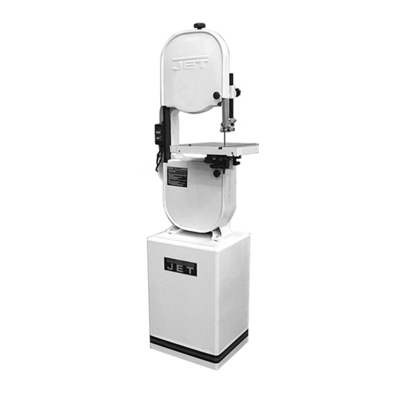
- Page 1 Operating Instructions and Parts Manual 14-inch Deluxe Band Saw Models: JWBS-14DX WMH TOOL GROUP 2420 Vantage Drive Elgin, Illinois 60123 Part No. M-710115 Ph.: 800-274-6848 Revision D 7/04 www.wmhtoolgroup.com Copyright © WMH Tool Group...
-
Page 2: Warranty And Service
This manual has been prepared for the owner and operators of a JET Model JWBS-14DX Band Saw. Its purpose, aside from proper machine operation, is to promote safety through the use of accepted operating and maintenance procedures. To obtain maximum life and efficiency from your band saw, and to aid in using the machine safely, read this manual thoroughly and follow all instructions carefully. -
Page 3: Table Of Contents
Table of Contents Warranty ... 2 Safety Warnings ...4-5 Safety Decal ... 6 Grounding Instructions ... 7 115 Volt Operation ... 7 230 Volt Operation ... 8 Specifications ... 9 Fasteners... 10 Receiving... 11 Assembly ... 11 Tilting the Table ... 14 Adjusting 90 Stop ... -
Page 4: Safety Warnings
As with all machines, there is a certain amount of hazard involved with the use of this band saw. Use the machine with the respect and caution demanded where safety precautions are concerned. When normal safety precautions are overlooked or ignored, personal injury to the operator can result. - Page 5 • SECURE WORK. Use clamps or a vise to hold the work when it’s practical. It’s safer than using your hand and it frees both hands to operate the tool. • DON’T OVERREACH. Keep proper footing and balance at all times. •...
-
Page 6: Safety Decal
SAFETY DECAL Familiarize yourself with the location and content of this decal on your machine. Fig. 1... -
Page 7: Grounding Instructions
Grounding Instructions Caution: This tool must be grounded while in use to protect the operator from electric shock. In the event of a malfunction or breakdown, grounding provides a path of least resistance for electric current to reduce the risk of electric shock. This tool is equipped with an electric cord having an equipment-grounding conductor and a grounding plug. -
Page 8: 230 Volt Operation
230 volt plug is installed. 4. The band saw with a 230 volt plug should only be connected to an outlet having the same configuration (Fig. 6). No adapter is available or should be used with the 230 volt plug. -
Page 9: Specifications
Specifications: JWBS-14DX Band Saw Stock Number ... 710115K Cutting Capacity (height)...6” Cutting Capacity (width) ...13-1/2” Minimum Blade Width...1/8” Maximum Blade Width...3/4” Blade Length...93-1/2” Blade Speed ... 3000 SFPM Table Size... 15” x 15” Table Slot Size... 3/8”D x 3/4”W Table Height from Floor ...43-1/2”... -
Page 10: Fasteners
Fasteners for JWBS-14DX A. Saw Body to Stand 4 – M8x40 hex cap screws (approx. 1-1/2" long) 8 – M8 flat washers 4 – M8 lock washers 4 – M8 hex nuts B. Strain Relief Plate to Stand 2 – M5x12 pan head machine screws C. -
Page 11: Receiving
If using a mobile base, lock the casters before assembling or operating the band saw. 3. With the aid of a second person, lift the saw body out of the shipping container and place onto stand top. Be sure front of saw (with JET... - Page 12 Failure to comply may cause serious injury! 4. Line up holes in saw body with holes in the top of the stand. Fasten saw body to the stand with four M8 x 40 hex cap screws, eight M8 washers, four M8 lock washers, and four M8 hex nuts (as shown in item A, page 10).
- Page 13 Slide the pulley cover down over the knobs, and tighten the knobs. 11. Attach trunnion support to saw body with two M8 x 30 hex cap screws and two M8 lock washers (as in item D, page two). See Figure 12.
-
Page 14: Tilting The Table
13. To mount the table, remove pin and insert from the table (Fig. 13). 14. Rotate the table so that the saw blade will slide through the slot in the table. Then orient the table so the screws will slide into the holes on the trunnion support brac ket. -
Page 15: Adjusting 90 O Stop
If necessary, adjust scale pointer to zero. Changing Blades WARNING Blade teeth are sharp! Use care when handling the saw blade. Failure to comply may cause serious injury! Disconnect machine from power source. Loosen blade tension by pushing up on the release lever (Fig. -
Page 16: Adjusting Blade Tension
Initially, set the blade tension to correspond to blade width. As you become familiar with the saw, you may find it necessary to change the blade tension from the initial setting. Changes in blade width and the type of material being cut will have an effect on blade tension. -
Page 17: Adjusting Upper Blade Guides & Blade Support Bearing
(D, Fig. 19) to move the guide block bracket in or out until the front edge of the guide blocks are just behind the "gullets" of the saw teeth. Tighten thumb screw (C, Fig. 19). Loosen thumb screw (E, Fig. 19) and turn knurled knob (F, Fig. -
Page 18: Adjusting Lower Blade Guides & Blade Support Bearing
(D, Fig. 20) to move the guide block bracket in or out until the front edge of the guide blocks are just behind the "gullets" of the saw teeth. Tighten thumb screw (C, Fig. 20). Loosen thumb screw (E, Fig. 20) and turn knurled knob (F, Fig. -
Page 19: Trouble-Shooting
TROUBLE-SHOOTING (JWBS-14DX Band Saw) PROBLEM POSSIBLE CAUSE Saw stops or will not start 1. Saw unplugged 2. Fuse blown or circuit breaker tripped 3. Cord damaged Does not make accurate 1. Stop not adjusted correctly 45 deg. or 90 deg. cuts 2. -
Page 20: Parts Breakdowns
Parts Breakdown JWBS-14DX Body Assembly... - Page 21 Parts List JWBS-14DX Body Assembly Index Part Description Size Qty. 1 ... 150100AW ...Upper Arm Frame ..1 2 ... 150037W ...Table..1 3 ... 100038 ...Table Pin ..1 4 ... 708719 ...Guide Block ..4 5 ...
- Page 22 Parts List JWBS-14DX Body Assembly Index Part Description Size Qty. 51 ...992009... Key... 5x5x20...2 52 ...BB-6204RS ... Ball Bearing ... 6204RS ...2 53 ...990293... Hex Head Bolt (Left Thread) ... M8x25 ...1 54 ...150054... Hex Head Bolt ..2 55 ...150055... Lower Support Bracket Post..1 56 ...150056...
- Page 23 Parts List JWBS-14DX Body Assembly Index Part Description Size Qty. 101... 150101 ...Lower Wheel Blade Guard ..1 102... WE050000 ...Gear Washer ...M5 ... 2 103... 998654 ...Strain Relief ..2 104... 100018 ...Indicator..1 105... WI080000...Gear Washer ...M8 ... 2 106...
-
Page 24: Closed Stand Assembly
Parts Breakdown JWBS-14DX Closed Stand Assembly... -
Page 25: Closed Stand Assembly
Parts List JWBS-14DX Closed Stand Assembly Index Part Description Size Qty. 1 ... 150501W ...Stand ..1 2 ... 150502W ...Door..1 3 ... 150503 ...Door Latch Assembly (Items 4 & 5) ..1 4 ... WBS14CS-04 ...Washer ..2 5 ... -
Page 26: Optional Accessories
Optional Accessories for JWBS-14DX Band Saw 708114 Three speed kit for WBS-14CS Produces speeds of 965, 1470, and 2465 SPFM. Includes four step motor pulley, intermediate pulley, V-belts, fasteners, and mounting instructions with parts list. 708718 JRF-14 Rip Fence Assembly Includes guide bars, rip fence assembly, fasteners, and mounting instructions with parts list. -
Page 27: Electrical Schematic - 115V
JWBS-14DX Electrical Schematic – 115V... -
Page 28: Electrical Schematic - 230V
JWBS-14DX Electrical Schematic - 230V WMH TOOL GROUP 2420 Vantage Drive Elgin, IL 60123 Ph: 800-274-6848 www.wmhtoolgroup.com...
Need help?
Do you have a question about the JWBS-14DX and is the answer not in the manual?
Questions and answers