Table of Contents
Advertisement
Advertisement
Table of Contents

Related Manuals for Jet JWBS-12OS


Summary of Contents for Jet JWBS-12OS
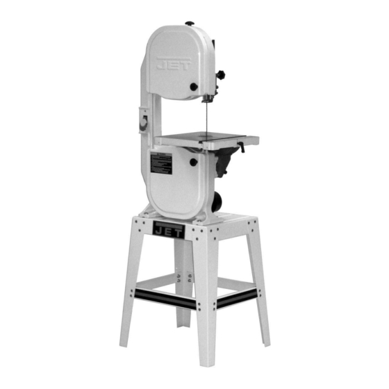
- Page 1 This Manual is Bookmarked Operating Instructions and Parts Manual 12-inch Woodworking Band Saw Model: JWBS-12OS WMH TOOL GROUP, Inc 2420 Vantage Drive Elgin, Illinois 60124 Part No. M-708901B Ph.: 800-274-6848 Revision C 06/07 www.wmhtoolgroup.com Copyright © 2007 WMH Tool Group, Inc.
-
Page 2: Warranty And Service
WMH Tool Group is consistently adding new products to the line. For complete, up-to-date product information, check with your local WMH Tool Group distributor, or visit jettools.com. WARRANTY JET products carry a limited warranty which varies in duration based upon the product (MW stands for Metalworking, WW stands for Woodworking). WHAT IS COVERED? This warranty covers any defects in workmanship or materials subject to the exceptions stated below. -
Page 3: Table Of Contents
Blade Guide Block Adjustment........................ 13 Blade Support Bearing Adjustment ......................14 Adjusting V-Belt Tension ......................... 14 Adjusting Blade Tracking......................... 12 Troubleshooting JWBS-12OS Band Saw ....................15 Parts ................................15 Ordering Replacement Parts........................15 Body Assembly............................16 Open Stand Assembly..........................20 Optional Accessories .......................... -
Page 4: Warnings
Warnings 1. Read and understand the entire owner's manual before attempting assembly or operation. 2. Read and understand the warnings posted on the machine and in this manual. Failure to comply with all of these warnings may cause serious injury. 3. - Page 5 19. Provide for adequate space surrounding work area and non-glare, overhead lighting. 20. Keep the floor around the machine clean and free of scrap material, oil and grease. 21. Keep visitors a safe distance from the work area. Keep children away. 22.
-
Page 6: Specifications
Motor ..........................1/2 HP, 1Ph, 115V Net Weight (lbs.) ........................132 (approx.) Shipping Weight (lbs.) ........................141 (approx.) * The JWBS-12OS Band Saw comes equipped with a 1/4"x82"x20" blade (Part No. 709392) factory installed. Read and understand the entire contents of this manual before attempting... -
Page 7: Shipping Contents
Shipping Contents Contents of the Carton Body Assembly (1) Table (1) Trunnion, Clamp Shoe & Lock Handle (1) Hose Adapter (1) Stand Leg (4) Base Plate (1) Hardware Bag for Stand (1) (contents shown below) Hardware Bag for Saw Body (1) (contents shown below) Short Support Plate (2) Long Support Plate (2) -
Page 8: Assembly
1. With the aid of a second person, lift the saw body (A) and place onto the stand top. Be sure front of saw (with JET logo) faces stand front (JET logo). 2. Place four M8 flat washers (P) on four M8x35 hex cap screws (N) and insert screws through four mounting holes in the bandsaw and stand. -
Page 9: Table Assembly
Table Assembly For this section, refer to Figure 3. 90º Table Stop 1. Thread the M6 hex nut (R) approximately half way onto the M6x70 hex cap screw (M). Then thread the screw half way into the bracket (A Adjustment will be made later. Trunnion Installation 2. -
Page 10: Grounding Instructions
Grounding Instructions may be used to connect this plug to a two-pole receptacle, as shown in Figure 5, if a properly grounded outlet is not available. The temporary General Information adapter should only be used until a properly grounded outlet can be installed by a qualified This Band Saw must be electrician. -
Page 11: Adjustments
Changing Blades Blade teeth are sharp! Use care when handling the saw blade. Failure to comply may cause serious injury. Note: JWBS-12OS Band comes equipped with a 1/4"x82"x20" blade (Part No. 709392) factory installed. Referring to Figure 8: 1. -
Page 12: Adjusting Blade Tension
4. Remove the table insert (B) and table pin (C). Adjusting Blade Tracking 5. Loosen blade tension by turning the tension Referring to Figure 9: knob (A) counterclockwise. 6. Remove blade (J) from upper and lower wheels Disconnect machine from the and from between the upper (F) and lower power source! Never adjust blade tracking with blade guides (G). -
Page 13: Upper Blade Guide Positioning
Upper Blade Guide Positioning Refer to Figure 10. The blade guard has been removed for clarity. Never operate the Band Saw without all guards in place and in working order. The upper blade guide assembly should be adjusted to just above the material being cut. To adjust: 1. -
Page 14: Blade Support Bearing Adjustment
Blade Support Bearing Adjustment Never operate the Band Saw without all guards in place and in working order. This adjustment is the same for upper and lower blade guides. Only the upper blade guide is shown. Referring to Figure 11: 1. -
Page 15: Troubleshooting Jwbs-12Os Band Saw
Troubleshooting JWBS-12OS Band Saw Trouble Probable Cause Remedy Saw unplugged. Check all plug connections. Saw stops or will not Fuse blown or circuit breaker tripped. Replace fuse, or reset circuit breaker. start. Cord damaged. Replace cord. Check blade with square and adjust Table stop not adjusted correctly. -
Page 16: Body Assembly
Body Assembly Index No. Part No. Description Size 1 ....JWBS12OS-001..Band Saw Frame ..................1 2 ....120002 .....Guide Bracket ..................2 3 ....TS-2246122 .....Button Head Socket Screw ........M6 x 12 ....... 6 4 ....120003 .....Stud......................1 5 ....NH121901....Nut................ M12 x 1.25 ....1 6 ....100016A....Upper Wheel Sliding Bracket ....... - Page 17 Body Assembly Index No. Part No. Description Size 62 .....ST049200 ....Tap Screw ............M4 x 8 ......3 63 .....120009 .....Hinge......................1 64 .....TS-1534041 .....Flat Head Screw ..........M5 x 10 ....... 3 65 .....120010 .....Guide Post Bracket .................. 1 66 .....990651 .....Knob..............
- Page 18 Body Assembly Index No. Part No. Description Size 125 ...JW1000....Reducer....................1 126 ...120026 .....Main Shaft ....................1 127 ...120024W....Bushing ....................1 128 ...TS-1522031 .....Set Screw............. M5 x 10 ....... 2 129 ...BB-6203VV ....Ball Bearing............6203LLU ..... 2 131 ...TS-1504041 .....Socket Head Cap Screw........
-
Page 20: Open Stand Assembly
Index No. Part No. Description Size 141 ...JWBS12OS-141..Stand Top....................1 142 ...JWBS12OS-142..JET Logo....................1 143 ...150603W....Support Leg....................4 144 ...612050W....Support Plate (long) ................. 2 145 ...612051W....Support Plate (short)................2 146 ...TS-1540061 .....Hex Nut ..............M8 ......40 147 ...SC089400 ....Carriage Bolt ............ -
Page 21: Optional Accessories
Optional Accessories 708916 ............Miter Gauge (JWBS-12MG) 708917 ............Rip Fence Assembly (JWBS-12RF) 82” Saw Blades 709390 ............1/8” x .018” x 8 T.P.I. Hook Tooth 709391 ............3/16” x .020” x 6 T.P.I. Skip Tooth 709392 ..... - Page 22 Notes...
- Page 23 Notes...
- Page 24 WMH Tool Group, Inc. 2420 Vantage Drive Elgin, Illinois 60124 Phone: 800-274-6848 www.wmhtoolgroup.com...
Need help?
Do you have a question about the JWBS-12OS and is the answer not in the manual?
Questions and answers