Ametek Sorensen DHP Series Manuals
Manuals and User Guides for Ametek Sorensen DHP Series. We have 3 Ametek Sorensen DHP Series manuals available for free PDF download: Operation Manual, Programming Manual

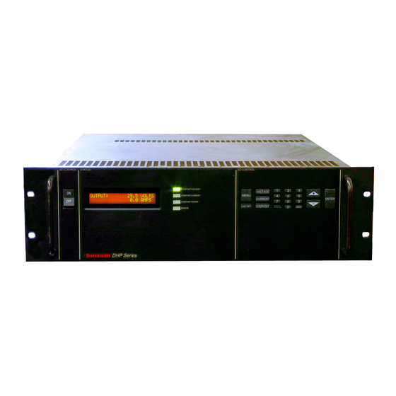
Ametek Sorensen DHP Series Operation Manual (56 pages)
Brand: Ametek
|
Category: Power Supply
|
Size: 1 MB
Table of Contents
Advertisement
Ametek Sorensen DHP Series Operation Manual (56 pages)
DC Power Supplies
Brand: Ametek
|
Category: Power Supply
|
Size: 1 MB
Table of Contents

Ametek Sorensen DHP Series Programming Manual (38 pages)
DC Power Supplies IEEE 488.2/RS-232 Options
Brand: Ametek
|
Category: Power Supply
|
Size: 0 MB
Table of Contents
Advertisement