Table of Contents
Advertisement
Advertisement
Table of Contents

Subscribe to Our Youtube Channel
Related Manuals for Avermedia AVerDiGi MOB1304 NET


Summary of Contents for Avermedia AVerDiGi MOB1304 NET
- Page 1 ® AVerMedia AVerDiGi MOB1304 NET User Manual Mar. 2010...
- Page 2 COPYRIGHT © 2010 by AVerMedia INFORMATION, Inc. All rights reserved. No part of this publication may be reproduced, transmitted, transcribed, stored in a retrieval system, or translated into any language in any form by any means without the written permission of AVerMedia TECHNOLOGIES, Inc.
- Page 3 SAFTETY WARNING WARNING TO REDUCE RISK OF FIRE OR ELECTRIC SHOCK, DO NOT EXPOSE THIS APPLIANCE TO RAIN OR MOISTURE CAUTION IF THERE IS ANY DAMAGE, SHORTAGE OR INAPPROPRIATE ITEM IN THE PACKAGE, PLEASE CONTACT WITH YOUR LOCAL DEALER. WARRANTY VOID FOR ANY UNAUTHORIZED PRODUCT MODIFICATION.
-
Page 4: Safety Precaution
SAFETY PRECAUTION Refer all work related to the installation of this product to qualified service personnel or system installers. Do not block the ventilation opening or slots on the cover. Do not drop metallic parts through slots. This could permanently damage the appliance. Turn the power off immediately and contact qualified service personnel for service. -
Page 5: Table Of Contents
Table of Contents Chapter 1 Introduction ..................1 Package Content ......................1 1.1.1 Optional Accessories ....................2 Front Panel ........................2 Back Panel ........................3 Setting Up the DVR Unit ....................4 1.4.1 Installing the Hard Disk ....................4 1.4.2 Mounting the DVR Unit .................... - Page 6 4.3.4 View the KML File on Google Earth ................. 63 Chapter 5 Backup Recorded Video File ............64 Familiarizing with HDD Backup Application ..............64 5.1.1 To Backup Recorded Video File ................65 Chapter 6 ImageVerification ................66 To Run the ImageVerification ..................66 Chapter 7 iEnhance ..................
-
Page 7: Chapter 1 Introduction
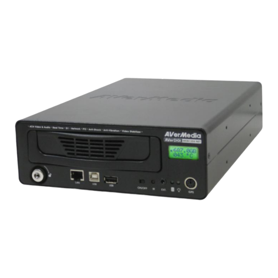
Chapter 1 Introduction AVerDiGi MOB1304 NET is a 4-channel stand-alone DVR unit for mobile solution that can be installed on the vehicle for security monitoring. It provides real-time monitoring and digital recording of surveillance video. Up to 4 video cameras and 4 sensor devices can be hooked up to this DVR unit. -
Page 8: Optional Accessories
1.1.1 Optional Accessories 3G USB Dongle (for 3G function) GPS receiver (for GPS function) Front Panel Name Function (1) SATA removable HDD For installing 2.5” or 3.5” SATA hard disk Drawer The DVR unit supports hot swap of hard disk. User can unlock the hard disk key lock and swap the hard disk while the DVR unit is running. -
Page 9: Back Panel
Back Panel Name Function (1) Power cable Connecting the power cord. The power cord divide into 4 lines and each line has sticker on it for function description. GND (Black): Power connecting negative(-)and camera negative(-) 12V~24V(Red): Power connecting positive(+) ... -
Page 10: Setting Up The Dvr Unit
AVerMedia has expressly advised about the risk of such damages. The entire risk arising out of the use of any information attached here with is borne by the recipient. - Page 11 Connect the power connector to the hard disk. And Using the both hand to hold and turn the hard disk then, put the hard disk inside the hard disk drawer drawer over carefully. And then, adjust the hard disk carefully. Please watch out the SATA cable when to appropriate position and secure the hard disk with put the hard disk into the hard disk drawer.
-
Page 12: Mounting The Dvr Unit
1.4.2 Mounting the DVR Unit The DVR unit can be mounted in two ways. User can uses the Z-brackets (4 screws included) to mount the DVR unit as the figure below shown. 1.4.2.1 Installing the lower Z-brackets 1. Screwed the Z-bracket for both side. 2. -
Page 13: Connecting Devices
1.4.3 Connecting Devices The following figure is a sample of DVR unit with all devices‟ connection: To avoid installing the MOB DVR unit in moisture location. To make sure the install location provides sufficient ventilation to keep proper operating temperature between 45°C and 5°C. Leave a front space that is enough for sliding removable hard disk drawer in and out. -
Page 14: Install On The Bus
1.4.3.1 Install on the Bus DVR Install Location: Under driver seat top or under storage box Do not install DVR unit near the door side and on the floor, those locations are high quake spot and are easily to damage the DVR unit. Circuit diagram:... -
Page 15: Install On The Car
Camera/LCD Monitor Install Location: Camera LCD Monitor The LCD monitor power can connect to the ignition of bus. The camera power is connected to the DVR camera power cable and plugs the video cable into DVR video input. 1.4.3.2 Install on the Car DVR Install Location: top or under storage box Hang inside the truck... -
Page 16: Connecting The Sensor/Relay/Rs485 Device
Camera/LCD Monitor Install Location: Camera LCD Monitor The LCD monitor power can connect to the ignition of bus. The camera power is connected to the DVR camera power cable and plugs the video cable into DVR video input. 1.4.4 Connecting the Sensor/Relay/RS485 Device The Sensor and Alarm ports enable you to connect (4) sensor inputs and (1) relay outputs. - Page 17 Sensor in and Alarm pinhole: The signal from the sensor (i.e., infrared sensors, smoke detectors, proximity sensors, door sensors, etc.) is being transmitted to the unit and this triggers the system to respond and send signal to relay device (i.e., alarm, telephone etc). Pin # Definition Sensor 1 signal...
-
Page 18: Familiarizing The Remote Control Buttons
Familiarizing the Remote Control Buttons Use the Remote control to operate the OSD menu on surveillance screen. Button Function + 0 , the DVR system will instantly Press playback backward the 60 seconds of the recorded file. As a Channel 1 in preview and playback mode As a channel 1 and preset position in PTZ mode As a channel 2 in preview and playback mode As a channel 3 and preset position in PTZ mode... - Page 19 Button Function (16) To enter the OSD Main menu / Exit from the main menu or sub-menu display ZOOM+ To zoom in view of PTZ camera (17) ZOOM- To zoom out view of PTZ camera PTZ camera control button. Press + camera channel button( )can (18)
-
Page 20: Using Ab Segment Function
1.5.1 Using AB Segment Function AB segment function allow user to set a video segment from A to B point and play on the surveillance screen until user stop. User also can backup AB segment video file to pen drive or external hard disk (see also 1.5.2). -
Page 21: Using Usb Backup Button
1.5.2 Using USB Backup Button User can press button to backup the AB segment video file. VIDEO BACKUP SETUP START 2009 / 01 / 09 11:36:21 2009 / 01 / 09 11:36:21 BACKUP CH BACKUP SIZE ~0MB BACKUP 1. Set the AB segment video (see 1.5.1). 2. -
Page 22: Controlling Ptz Camera
Controlling PTZ Camera Using remote control, user can easily control PTZ camera at local site. Before starting, please go to OSD menu to enable PTZ control (see 3.1 Menu Function: PTZ Setup). 1.6.1 To Enter the PTZ Mode To control PTZ camera, user need to enter the PTZ mode first. Press button, and camera channel number button ( . -
Page 23: To Set Preset Position
1.6.2 To Set Preset Position User can set 9 preset positions for PTZ camera. Using button to set the preset position. 1. Press and camera channel number button ( to enter PTZ mode. 2. Using to adjust the PTZ camera to the position that user wants. 3. -
Page 24: Chapter 2 Operating The Mob1304 Net
Chapter 2 Operating the MOB1304 NET Using the MOB1304 NET for the First Time For the first time using the DVR unit, suggest user connect with the LCD monitor and setup DVR unit by using remote control. Once the DVR unit has been set up, user can operate the DVR unit through the remote control and LED panel that is located front panel of DVR unit. -
Page 25: Surveillance Screen
CHECK PASSWORD ENTER PASSWORD ****** EXECUTE 7. When hard disk format is done, please adjust the system date and time in order to have the correct recording date and time. to select SYSTEM → 8. Press to call up the OSD menu, and then, use DATE/TIME and press to make a selection. - Page 26 Preview Mode Symbol Description DVR is recording Audio is enabled Speaker is available Motion recording Hard disk capacity USB device is plugged Playback Mode Symbol Description Playback the recorded video Audio is enabled AB segment is set and playing Recorded video is playback at backward speed(2x, 4x, 8x, 16x, 32x, or 64x) Recorded video is playback at faster forward speed(2x, 4x, 8x, 16x, 32x, or 64x) Always Recording...
- Page 27 By enabling TIME STAMP function, current date and time could be displayed on each channel screen to verify the recording date and time. Please follow the below steps to enable TIME STAMP. 1. Press to call out OSD menu. 2. Using move the highlight to CAMERA/REC and press to make a selection.
-
Page 28: Playback The Video
Playback the Video To playback recorded video, user doesn‟t need to stop recording. DVR system supports recording and playback simultaneously. 2.3.1 To Playback Video SEARCH METHOD 1. Press (play). TIME SEARCH FILE LIST SMART MOTION SEARCH 2. Use the buttons to go up and down and select TIME SEARCH, FILE LIST, or SMART MOTION SEARCH. - Page 29 4. And then, select SEARCH AREA to mark an area to search. Use the , and to move the block and press to confirm. To exit, press 5. To start searching, select the SEARCH EXECUTION. 6. When the playback file is found, the DVR system will start playback automatically.
-
Page 30: Using The Gps Function
Using the GPS Function MOB DVR supports GPS that GPS data can be recorded and viewed the actual location by using Google Earth. 2.4.1 Installing the GPS Device User needs to install the GPS device on MOB DVR in order to receive the GPS data. GPS device is an optional accessory, please contact with your local dealer for purchasing. -
Page 31: Enabling The Gps Function
2.4.2 Enabling the GPS Function GPS must be enabled in order to receive the GPS data. Following the below steps to enable the GPS function on the MOB DVR. 1. Press or use mouse right-click on the screen to call out the OSD menu. 2. -
Page 32: Viewing The Gps Information
2.4.3 Viewing the GPS Information There are several ways to view the GPS data – in preview mode, WebViewer, UPC, Google Earth, Remote Console, and CMS. Preview Mode After GPS has enabled, user should see the GPS data display on the preview screen. GPS data will change when receive the new data. - Page 33 USB Playback Console The recorded file that contains GPS data can be view when playback on USB Playback Console (UPC). Connect the HDD that contains recorded file from MOB DVR to your PC Install the UPC application from the Software CD on your PC. Run the UPC and select DVR Recorded File(HD) from Disk Select and click OK.
- Page 34 Google Earth By using Google Earth, user can view the video segment that has contains GPS data save in *.KML format from UPC. Install the Google Earth at http://earth.google.com. Using UPC to playback the recorded file from hard disk that is containing of recorded video data of MOB DVR(see also Chapter 4.3.2)
- Page 35 Remote Console In Remote Console UI, user can enable GPS function to view the MOB DVR server location on the Google map according to the GPS data that is received from GPS device has installed on the MOB DVR system. Follow the below steps to view the GPS data from the remote site.
- Page 36 User can change display mode of the Google map and zoom in /out of the map. Exit the Google Map window Click to select different display mode – Map, Hybrid, Satellite, or terrain. This icon represent as the DVR server. Zoom in/out the Map ...
- Page 37 6. Select the Video Quality to High, and then, mark the Show POS message for display the GPS data on the Monitor. 7. Click OK to save and complete the change. 8. If the MOB DVR server hasn‟t been added any channels for monitoring, please refer to Chapter 4.3 of the CMS user‟s manual to add the channels for monitoring.
- Page 38 Viewing the GPS Data on the Google Map: Following the below steps to view the GPS data on the Google Map. 1. In the Monitor mode, right-click on the channel that is monitored from MOB DVR server. 2. The shortcut menu will appear. And then, select the Start GPS. 3.
- Page 39 Click to select the display mode – Map, Hybrid, Satellite, or terrain. Listing all channels that have been enabled the GPS function. Click to view different Zoom in/out the split screen mode when Google Map. there is more than one channel on the Google map.
-
Page 40: Chapter 3 Osd Navigation Tree
Chapter 3 OSD Navigation Tree The follow figure is an OSD menu tree map. To call out the OSD menu, press button on the remote control. -
Page 44: Menu Function
Menu Function To navigate in the OSD menu, press to call up and exit from the main menu or sub-menu display. Then use buttons to go up and down and select the items in the menu list or change the settings. Use button to enter sub-menu or make a selection. - Page 45 OSD MENU Description GENERAL SETUP PRE RECORD RECORD MODE Set the pre-recording time in seconds when alarm has occurred. DVR NAME COMPANY TIME STAMP WATERMARK AUTO RECORD PRE RECORD 00 SEC CHANNEL SETTING SETUP CHANNEL SETTING ENABLE Configure the parameters of each channel. RECORD AUDIO RECORD ENABLE...
- Page 46 OSD MENU Description PTZ SETUP PTZ SETUP ENABLE To enable PTZ camera control by remote control and setup PTZ camera parameters. PROTOCOL CANON VC - 4CR BAUD RATE 9600 AUTO PAN ENABLE DWELL TIME 010S 010S 010S 010S Select the channel of PTZ camera. If the PTZ camera is connecting on channel 1, then select the camera 1 for PTZ video to be display on channel 1.
- Page 47 OSD MENU Description DISPLAY SETUP COLOR ADJUSTMENT COLOR ADJUSTMENT To adjust the brightness, contrast, hue, and saturation value of VIDEO OUT SETTING VIDEO SHIELD channel video. To reset the setting, select RESET TO DEFAULT VGA - TV SELECTION MAIN - MAIN VALUE.
- Page 48 OSD MENU Description DISPLAY SETUP VGA - TV SELECTION COLOR ADJUSTMENT Select the VGA and TV output order. VIDEO OUT SETTING VIDEO SHIELD MAIN - MAIN: Both VGA and TV output surveillance video on VGA - TV SELECTION MAIN - MAIN SPOT MONITOR QUAD screen.
- Page 49 OSD MENU Description MAIN MENU EVENT SETUP CAMERA/REC Configure alarm, sensor, motion, temperature, shock, and voltage. DISPLAY SCHEDULE EVENT SETUP EVENT SETUP STORAGE ALARM SETTING NETWORK SENSOR SETTING SYSTEM MOTION DETECTION MISCELLANEOUS TEMPERATURE SHOCK DETECTION VOLTAGE ALARM SETTING Configure parameters of alarm. ALARM SETUP ALARM TYPE RECORD...
- Page 50 OSD MENU Description ALARM SETUP VIDEO LOSS ALARM TYPE ALARM PERIOD 005 SEC Select the channel that will send out the alarm when video is lost. ALARM CONTINUOUSLY SELECT / DESELECT ALL REMOTE TIRGGER SENSOR MOTION DETECTION TEMPERATURE Allow user to trigger alarm from remote site. MEMS VOLTAGE HDD FAIL...
- Page 51 OSD MENU Description EVENT SETUP MOTION DECTECION ALARM SETTING MOTION DETECTION SETUP SENSOR SETTING MOTION DETECTION CH1 CH2 TEMPERATURE ENABLE SENSTIVITY SHOCK DETECTION MASK SETUP VOLTAGE ENABLE Enable/disable the channel to detect motion. SENSITIVITY Set the sensitivity level. The sensitivity is from HI (High), 9~ 2 and LO (Low).
- Page 52 OSD MENU Description ALARM THRESHOLD TEMPERATURE SETUP Set the temperature high/low limit (0~100°C/55 ~ 95°C) to prevent TEMP. TYPE FAN ON DVR unit overheating/overcooling. When DVR unit temperature FAN OFF reaches the high/low limit, the system will show the warning message ALARM THRESHOLD 060/005 HDD STOP...
- Page 53 OSD MENU Description MAIN MENU STORAGE SETUP CAMERA/REC To format hard disk and backup recorded video to external USB DISPLAY SCHEDULE storage device(pen drive or external hard disk) EVENT SETUP STORAGE STORAGE SETUP NETWORK HDD OVERWRITE SYSTEM HDD SIZE 953 , 849MB MISCELLANEOUS HDD USED 279MB...
- Page 54 OSD MENU Description STORAGE SETUP VIDEO BACKUP HDD OVERWRITE HDD SIZE 953 , 849MB To backup the recorded video by selected period. HDD USED 279MB HDD FORMAT VIDEO BACKUP SETUP VIDEO BACKUP START 2009 / 01 / 06 14 : 50 : 10 2009 / 01 / 06 14 : 52 : 10 BACKUP CH BACKUP SIZE...
- Page 55 OSD MENU Description MAIN MENU NETWORK SETUP CAMERA/REC Setup the network parameters for the internet or intranet remote DISPLAY SCHEDULE monitor or playback. EVENT SETUP STORAGE NETWORK SETUP NETWORK IP MODE STATIC SYSTEM VIDEO PORT 0080 MISCELLANEOUS UPGRADE PORT 5005 STREAM SETUP WIRELESS LAN IP MODE...
- Page 56 OSD MENU Description NETWORK SETUP STREAM SETUP IP MODE STATIC VIDEO PORT 0080 Configure the network stream of channel. UPGRADE PORT 5005 STREAM SETUP ENABLE WIRELESS LAN Enable/disable the stream setup of channel. Set the frame rate of stream. QUALITY Select the quality for stream recording.
- Page 57 OSD MENU Description MAIN MENU SYSTEM SETUP CAMERA/REC To configure the parameters that relate with DVR system. DISPLAY SCHEDULE SYSTEM SETUP EVENT SETUP SYSTEM INFO STORAGE CONFIGURATION NETWORK SYSTEM DATE / TIME MISCELLANEOUS PASSWORD CHANGE AUDIO SETUP DELAY POWER OFF 0 MIN INSTANT PLAYBACK 060 SEC...
- Page 58 OSD MENU Description SYSTEM SETUP LOG SETUP SYSTEM INFO CONFIGURATION To search event log. Select the SEARCH TIME and select SEARCH EXECUTION to start DATE / TIME PASSWORD CHANGE searching. The search result will be list out. User can select the log to AUDIO SETUP view but some of logs are not viewable.
- Page 59 OSD MENU Description SYSTEM SETUP PASSWORD CHANGE SYSTEM INFO CONFIGURATION PASSWORD CHANGE SETUP PASSWORD SETUP DATE / TIME ADMINISTRATOR PASSWORD CHANGE OPERATOR AUDIO SETUP USER INSTANT PLAYBACK 060 SEC EXTENSION SETUP LANGUAGE ENGLISH Enable/disable full system password protection. This would prevent unauthorized user to stop video recording, change system settings and formatting the hard disk.
- Page 60 OSD MENU Description SYSTEM SETUP AUDIO SETUP SYSTEM INFO CONFIGURATION AUDIO SETUP AUDIO MUTE DATE / TIME AUDIO OUT @ QUAD PASSWORD CHANGE VOLUME ADJUSTMENT AUDIO SETUP RESET TO DEFAULT INSTANT PLAYBACK 060 SEC EXTENSION SETUP LANGUAGE ENGLISH DELAY POWER OFF Set the time for DVR system to power off self after the vehicle has turn off the engine.
- Page 61 OSD MENU Description MAIN MENU MISCELLANEOUS SETUP CAMERA/REC DISPLAY To setup multiple control, entertainment, GPS, GSM, and 3G SCHEDULE function. EVENT SETUP STORAGE MISCELLANEOUS SETUP NETWORK MUTLIPLE DVR SYSTEM MISCELLANEOUS ENTERTAINMENT MUTLIPLE DVR Enable/disable multiple DVR system remote control. When user has more than one DVR system, user can use MULTIPLE DVR function to control all DVR system by single remote control.
- Page 62 OSD MENU Description MISCELLANEOUS SETUP GPS SETUP MUTLIPLE DVR ENTERTAINMENT To enable/disable GPS information message display on surveillance screen. GPS SETUP DISPLAY MESSAGE LATITUDE LONGITUDE HEADING SPEED OVER GROUND KM / MILE LATITUDE Enable/disable to display latitude information on surveillance screen. LONGITUDE Enable/disable to display longitude information on surveillance screen.
-
Page 63: Chapter 4 Using The Usb Playback Console
Chapter 4 Using the USB Playback Console Recommended system requirements Pentium® 4 2.4GHZ or above Windows® 2000/ XP/Vista DDR 256 MB Graphic function must support DirectDraw Audio card or built-in Speaker 1 available USB2.0 port Installing the USB Playback Console To install the USB Playback Console: Place Installation CD into the CD-ROM drive. -
Page 64: Running The Usb Playback Console
Running the USB Playback Console To run the application, click the icon on the PC desktop Name Function (1) Split Screen Mode Select from different screen view to playback the recorded video file of the entire camera or one camera on screen. (2) Exit Close the application. - Page 65 Name Function (6) Archive To select the video file source for playing. DVR Recorded File (HD): To playback the recorded video from the hard disk which was recording video on the DVR system. (see also Chapter 4.3.2) Backup File(.dvr): The file is backup and save in *.dvr file format. (see also Chapter 4.3.3) Backup File (.avf): The file is backup and save to external USB storage device in...
-
Page 66: To Cut And Save The Portion Of The Recorded Video
Name Function To enhance the video quality. Set the de-interlace mode to #1, if you are capturing (16) De-interlace motionless picture and #2, if it captures lots of movement. When playback *.dvr file, click watermark button to verify the correction of playback video. -
Page 67: Playback Dvr Recorded File From Hard Disk
4.3.2 Playback DVR Recorded File from Hard Disk Please have the hard disk which containing of recorded video data install on your PC or using external USB enclosure to connect to your PC. Click Archive button Select DVR Recorded File(HD) and click OK. Select the hard disk drive from Select Disk window and click OK. -
Page 68: Playback Backup File(*.Dvr)
4.3.3 Playback Backup File(*.dvr) Click Archive button. Select Backup File(*.dvr) and click OK. Locate the backup file folder and click OK. When open the backup video file, just locate the where backup file folder is. Select the date on the calendar and the time from 00 to 23 to where to start playing the recorded video file. -
Page 69: View The Kml File On Google Earth
4.3.4 View the KML File on Google Earth 1. Playback the recorded file from hard disk that is containing of recorded video data of MOB DVR(see also Chapter 4.3.2) The recorder file must contain GPS data in order to save in *.KML format and view on Google Earth. 2. -
Page 70: Chapter 5 Backup Recorded Video File
Chapter 5 Backup Recorded Video File HDD Backup application provides user an interface to view recorded video from hard disk and backup it. Familiarizing with HDD Backup Application Name Function Date Select the date for events Hour and Channel User can select the hour and channel for events. : All events in this hour and channel have been selected. -
Page 71: To Backup Recorded Video File
Name Function Source Disk To select the hard disk drive (10) Target Path To locate on where user wants to save the file (11) Event (%) Display the backup progress rate of event in percentage (12) Total (%) Display the total backup progress rate in percentage (13) Stop Stop backup progress (14) Start... -
Page 72: Chapter 6 Imageverification
Chapter 6 ImageVerification Image Verification is a watermark-checking program to identify the authenticity of a saved image (e.g. by snapshot). This program can only verify uncompressed bmp image files. To Run the ImageVerification To run the ImageVerification application, click the Watermark button on USB Playback Application main interface. -
Page 73: Chapter 7 Ienhance
Chapter 7 iEnhance The bundled iEnhance is a video editing tool and can be used with *.dvr and *.avf video file. It allows you to adjust the video picture quality, segment and save the selected portion of the video, zoom in and out the image, and print or save the screen shot. You can also save the setting and apply it on other files. -
Page 74: To Use Istable
Name Function (14) Effects Gray Scale: convert the image into black and white (monochrome). Normalize: adjust the brightness intensity. Equalize: automatically adjust the images that are too dark. De-interlace: smooth out the overlying frames. Static: de-interlace for motionless scene. Dynamic: de-interlace for moving scene. (15) Picture Adjust the Brightness, Contrast, Saturation, Hue and Gamma. -
Page 75: Chapter 8 Using The Remote Programs
Chapter 8 Using the Remote Programs User can use Microsoft Internet Explorer to access DVR system by entering the IP address. To use this feature, make sure that your PC and DVR server both are connected to the internet and the Network feature is enabled. - Page 76 After installing the WebCamX.cab and when connecting to the DVR system, you are required to enter default account ID (default is ADMIN) and password (default is 111111) and select the type of network. Changing account password is strongly recommended.
-
Page 77: Familiarizing The Webviewer Buttons
Familiarizing the WebViewer Buttons Right-clicking on the WebViewer video screen, enables you to start video recording, switch camera and enable/disable DirectDraw. Name Function (1) DirectDraw Enhance the video quality. Not all graphic cards can support this function. If you cannot see the screen display correctly or screen is messed, please check with VGA card vendor. - Page 78 Name Function (13) Select cameras to Select to the view camera from different server. In Select Camera dialog box, Display view column, click to enable/disable viewing the camera. Click Add Server and select the server type between DVR and IP Cam to add. Click Delete Server to delete the selected item.
-
Page 79: To Setup Remote System Setting
8.1.1 To Setup Remote System Setting Click OK to exit and save the setting and Cancel to exit without saving the setting. The setting here applies to Remote DVR system only. After changed the DVR system setting, refresh your web browser in order to apply the new setting to the DVR system. - Page 80 (4) Display - VGA-TV Selection: Select the VGA and TV output order. MAIN - MAIN: Both VGA and TV output surveillance video on screen. MAIN – SPOT: VGA output surveillance video and TV output the alarm event video. ...
-
Page 81: Camera Setup
8.1.1.2 Camera Setup (1) General - Time Stamp Enable/disable the time and date display on the each channel. - Auto Record Enable/disable auto continue recording when interrupted (i.e., power breakdown, video playback or configuration setup). It starts to record after 10 second of idleness. This is applicable in Always Record mode. -
Page 82: Record Setup
8.1.1.3 Record Setup (1) Record Mode Select D1/CIF/D1 Enhance recording mode. Under D1 mode, the video recording is in full screen resolution and takes turns from one channel to the next one when Auto Scan enables. Each channel is recorded up to a maximum frame rate of 30/25fps(NTSC/PAL). User can switch to view the video in full screen or QUAD screen. - Page 83 more hard disk space. - Quality Select the video quality setting from BEST, HIGH, GOOD, MEDIUM, NORMAL or LOW. Choosing higher quality allows user to record less hours but the quality of the recorded video is better. - FPS(alarm) Set the number of frames per second to be recorded when alarm has occurred. The higher the frame rate, it uses more hard disk space.
-
Page 84: Alarm Setup
8.1.1.4 Alarm Setup (1) Alarm Type Select the way of alarming – REC, EMAIL, GSM, BUZZER, or RELAY. (2) Alarm Continuously Enable/disable the alarm event continuously to display on the spot monitor until the next alarm event is coming in. (3) Alarm Period Set the amount of time(in seconds) to sending the alarm once triggered. - Page 85 Set a specific temperature limit for fan active. When the hard disk temperature reaches temperature limit, the fan will be active. - FAN OFF Set a specific temperature limit for fan stop. When the hard disk temperature drop to the temperature low limit, the fan will switch to off if the fan was on.
-
Page 86: Network Setup
8.1.1.5 Network Setup (1) IP Mode The system provides 3 types of IP setup mode – STATIC, DHCP, and PPPOE. STATIC: Assigns a constant IP address for the DVR system. DHCP: Assign the IP address by local DHCP server to DVR system. The DHCP (Dynamic Host Configuration Protocol) is a set of rules used by a communications device (such as a computer, router or networking adaptor) to allow the device to request and get an Internet address from a server which has a list of addresses available for assignment... - Page 87 Security: Select the type of encryption – WEP-64-PSK, WEP-128-PSK, WPA-TKIP-AES. Country Code: Then country code is depending on the regulatory region where the AP device is sold. (5) WLAN IP Setting ENABLE Enable/disable the wireless function. IP MODE Select the IP mode of wireless – STATIC or DHCP. ...
-
Page 88: User Setup
8.1.1.6 User Setup To change Admin, operator, and user account‟s password. Enter the new password in Password and re-enter again in Password Confirm. Click OK to complete the change. -
Page 89: Familiarizing The Webviewer Ptz Buttons
Familiarizing the WebViewer PTZ Buttons Name Function (1) Direction buttons Adjust and position the focal point of the PTZ camera. Click the center to pan automatically. (2) Zoom +/- Zoom in and out the image. (3) Select PTZ Choose to enable/disable the PTZ camera. In the Select PTZ dialog box, Select column, click to enable/disable viewing and controlling the PTZ camera. -
Page 90: Familiarizing The Remote Console Buttons
Familiarizing the Remote Console Buttons Right-click on the screen can enable GPS function (see also Chapter 2.4.3) if the remote MOB DVR server has installed the GPS device and enabled the GPS function. Name Function (1) Exit Close/minimize remote console application (2) Split Screen Mode Select from 2 different split screen type to playback the recorded video file of all the cameras or one camera on the screen. -
Page 91: To Setup Remote Console Setting
8.3.1 To Setup Remote Console Setting Click Setup button to call out the System Setting windows. Click OK to exit and save the setting and Cancel to exit without saving the setting. (1) Storage Path Set the directory on where to save the data. When there is not enough free space to record one hour data, the system automatically replaces the oldest data. -
Page 93: Using The Remote Playback
Using the Remote Playback To use this feature, first switch to playback mode by clicking the Playback icon, and then, select the source of the file. In the Select Playback Mode dialog box, choose Local Playback to open the file that is recorded in the Remote Console, and Remote Playback to open the file that is recorded on the DVR server. -
Page 95: Familiarizing The Local Playback Buttons
8.4.1 Familiarizing the Local Playback Buttons Name Function (1) Exit Click to exit or minimize the application. The password is required for exit or minimize. Show the progress of the file being played. You may move the bar to seek at any (2) Progress bar location of the track. - Page 96 Name Function Select the date on the calendar and the time from 00 to 23 to where to start playing the (6) Archive recorded video file. - Also, user can open the recorded file from certain location by click OPEN FILE button - Click Channel 01~ 16 and Channel 17 ~ 32 button to switch to different channel group of playback calendar if the DVR has more than 16 channels.
-
Page 97: To Cut And Save The Wanted Portion Of The Recorded Video
8.4.1.1 To Cut and Save the Wanted Portion of the Recorded Video Use the Playback Control buttons or drag the bar on the playback progress bar and pause on where you want to start the cut. Then, click Segment to set the begin mark. Use the Playback Control buttons or drag the bar on the playback progress bar and pause on where you want to end the cut. -
Page 98: To Search Using The Visual Search
8.4.1.2 To Search Using the Visual Search 1. Click Visual Search. In the Visual Search Setting dialog box, select the Camera number and the date. Then click When a series of frames appear by date, click on the frame to display another series of frames and search by every Hour of that date, every 3Minutes of that hour, every 10 Seconds of that minute, every Second of that 10 seconds. -
Page 99: To Search Using The Intelligent Search
8.4.1.3 To Search Using the Intelligent Search 1. Click on the video screen on where you want to search. 2. Click Intelligent Search. The Intelligent Search text (red) would appear at the lower left corner of the screen. 3. When the Intelligent Search Setting dialog box and motion detector frame appear, you may adjust the sensitivity bar and the motion detector frame size and location. -
Page 100: Familiarizing The Download And Playback Buttons
8.4.2 Familiarizing the Download and Playback Buttons Name Function (1) Exit Click to close the application. (2) Progress bar Show the progress of the file being played. You may move the bar to seek at any location of the track. (3) Playback Begin: Move at the beginning of the recorded video file. - Page 101 Name Function (8) Full screen View in Playback-compact mode. To return, press the right button of the mouse or ESC on the keyboard. When you switch to full screen in multiple-screen mode, Left click to toggle to only display one of the video in the multiple-screen mode or all. (9) Event Log Show the record of activities that take place in the system.
-
Page 102: Warranty Notice
Any other cause which does not relate to a product defect. 3. Cartons, cases, batteries, cabinets, tapes, or accessories used with product. 4. AVerMedia does not warrant that this product will meet your requirements; it is your responsibility to determine the suitability of this product for your purpose.
Need help?
Do you have a question about the AVerDiGi MOB1304 NET and is the answer not in the manual?
Questions and answers