Table of Contents
Advertisement
Quick Links
Advertisement
Table of Contents

Related Manuals for Avermedia AVerDiGi EH5108 LITE


Summary of Contents for Avermedia AVerDiGi EH5108 LITE
- Page 1 Jan. 2011...
- Page 2 COPYRIGHT © 2011 by AVerMedia Information, Inc. All rights reserved. No part of this document may be reproduced or transmitted in any form, or by any means without the prior written permission of AVerMedia Information Inc. AVerMedia Information Inc. reserves the rights to modify its models, including their characteristics, specifications, accessories and any other information stated herein without notice.
- Page 3 WARNING TO REDUCE RISK OF FIRE OR ELECTRIC SHOCK, DO NOT EXPOSE THIS APPLIANCE TO RAIN OR MOISTURE CAUTION IF THERE IS ANY DAMAGE, SHORTAGE OR INAPPROPRIATE ITEM IN THE PACKAGE, PLEASE CONTACT WITH YOUR LOCAL DEALER. WARRANTY VOID FOR ANY UNAUTHORIZED PRODUCT MODIFICATION NOTICE - INFORMATION IN THIS DOCUMENT IS SUBJECT TO CHANGE WITHOUT NOTICE.
-
Page 4: Table Of Contents
EH5108H series ......................... 3 1.1.4 EH5216H series ......................... 4 1.1.5 EXR5008/EXR5016 series ....................5 1.1.6 Optional Accessories ......................5 Front Panel ..........................6 1.2.1 EH5108 Lite/EH5108H Lite/EH5216Lite/EH5216H Lite EXR5008 Lite/EXR5016 Lite ..6 1.2.2 EH5108 /EH5216 /EH5108H /EH5216H /EXR5008 /EXR5016 ........6 1.2.3... - Page 5 2.2.2.2 Setup the IP PTZ Camera ..................37 2.2.3 Using Event Log Viewer ....................38 2.2.3.1 Using POSViewer ......................39 Familiarizing the Buttons in Playback Mode ................. 40 2.3.1 To Cut and Save the Portion of the Recorded Video ............42 2.3.2 To Bookmark a Video Section ..................
- Page 6 Familiarizing the Buttons in WebViewer ................94 6.1.1 To Setup Remote System Setting ..................96 6.1.1.1 System Setting ......................96 6.1.1.2 Camera Setting ......................98 6.1.1.3 Record Setting ......................102 6.1.1.2 Network Setting ......................106 6.1.1.3 Alarm Setting ......................108 Familiarizing the Buttons in WebViewer PTZ ...............
- Page 7 Remote Setup ........................152 8.2.1 To Add DVR server ......................152 8.2.2 To Setup Remote System Setting ................... 153 8.2.2.1 System Setting ......................153 8.2.2.2 Camera Setting ......................155 8.2.2.3 Record Setting ......................159 8.2.2.4 Network Setting ......................163 8.2.2.5 Alarm Setting ......................
-
Page 9: Chapter 1 Introduction
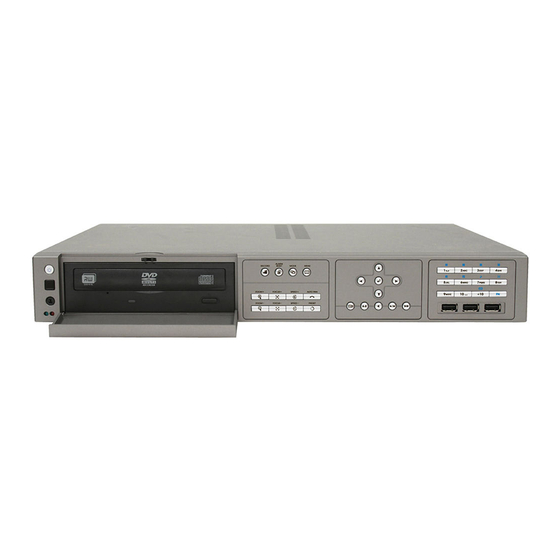
(1) DVR unit EH5108 EH5108 EH5108 Lite (2) AVerMedia USB optical mouse (3) Quick Installation Guide (4) Power adaptor (5) Power Cord * The power cord varies depending on the standard power outlet of the country where it is sold. -
Page 10: Eh5216 Series
(1) DVR unit EH5216 EH5216 EH5216 Lite (2) AVerMedia USB optical mouse (3) Quick Installation Guide (4) Power adaptor (5) Power Cord * The power cord varies depending on the standard power outlet of the country where it is sold. -
Page 11: Eh5108H Series
(1) DVR unit EH5108H EH5108H EH5216H Lite (2) AVerMedia USB optical mouse (3) Quick Installation Guide (4) Power adaptor (5) Power Cord * The power cord varies depending on the standard power outlet of the country where it is sold. -
Page 12: Eh5216H Series
(1) DVR unit EH5216H EH5216H EH5216H Lite (2) AVerMedia USB optical mouse (3) Quick Installation Guide (4) Power adaptor (5) Power Cord * The power cord varies depending on the standard power outlet of the country where it is sold. -
Page 13: Exr5008/Exr5016 Series
(1) DVR unit EXR5008/EXR5016 EXR5008 /EXR5016 EXR5008 Lite/EXR5016 Lite (2) AVerMedia USB optical mouse (3) Quick Installation Guide (4) Power adaptor (5) Power Cord * The power cord varies depending on the standard power outlet of the country where it is sold. -
Page 14: Front Panel
Front Panel 1.2.1 EH5108 Lite/EH5108H Lite/EH5216Lite/EH5216H Lite EXR5008 Lite/EXR5016 Lite Name Function (1) System Power System power status indicators. Indicate running state of system. Lights when the system is indicator running. (2) Record indicator When DVR system is recording, the light will keep flashing. - Page 15 Name Function Call out system setup menu on preview mode Move to left direction on menu control To move PTZ camera lens to left in PTZ mode Move to right direction on menu control To move PTZ camera lens to right in PTZ mode To move PTZ camera lens to up (10) Control Buttons Move to up direction on menu control...
- Page 16 Name Function A functional key for multiple system control. Press to switch to FN mode (The word “FN” will show up in the left bottom corner on screen). Press button again to exit FN mode (The “X” will show up in the left bottom corner on screen). : Switch to single screen display mode : Switch to QUAD display mode : Switch to 9 spilt screen display mode...
-
Page 17: Eh5216/Eh5108/Exr5008/Exr5016
1.2.3 EH5216/EH5108/EXR5008/EXR5016 Name Function - Power indicator (left): System power status indicators. Indicate running state of system. (1) System indicator Lights when the system is running. - Record indicator (right): When DVR system is recording, the light will keep flashing. - Page 18 Name Function Move to left direction on menu control To move PTZ camera lens to left in PTZ mode Move to right direction on menu control To move PTZ camera lens to right in PTZ mode To move PTZ camera lens to up (9) Control Buttons Move to up direction on menu control To move PTZ camera lens to down...
- Page 19 Name Function A functional key for multiple system control. Press to switch to FN mode (The word “FN” will show up in the left bottom corner on screen). Press button again to exit FN mode(The “X” will show up in the left bottom corner on screen). : Switch to single screen display mode : Switch to QUAD display mode : Switch to 9 spilt screen display mode...
-
Page 20: Back Panel
Back Panel 1.3.1 EH5108 series/EH5108H series Name Function LAN Port For Gigabit Ethernet connection RS232 port For POS device connection Input/output audio signal to audio input/output device. Audio In/Audio Out/MIC In Audio input:8 channels Audio output: 1 channel Microphone input: 1 channel The audio input and output device has its own power supply is necessary. -
Page 21: Eh5216 Series/Eh5216H Series
1.3.2 EH5216 series/EH5216H series Name Function LAN Port For Gigabit Ethernet connection RS232 port For POS device connection Input/output audio signal to audio input/output device. Audio In/Audio Out/MIC In Audio input:16 channels Audio output: 1 channel Microphone input: 1 channel The audio input and output device has its own power supply is necessary. -
Page 22: Exr5008/Exr5016 Series
1.3.3 EXR5008/EXR5016 series Name Function LAN Port For Gigabit Ethernet connection Output audio signal to audio output device. Audio Out/MIC In Audio output: 1 channel Microphone input: 1 channel The audio output device has its own power supply is necessary. VGA Out Output the video signal to a CRT or LCD monitor eSATA port... -
Page 23: Setting Up The Dvr Unit
® to the reliability of the hard disk function or its compatibility. In no event AVerMedia shall be liable for damages, with respect to any business interruption of clients, lost profits, loss of programs or other data on your information handling system or otherwise. - Page 24 5. The hard disk plate can be installed 3 hard disks. User 6. Turn the plate and hard disk over carefully and screwed can choose the position and place the hard disk on it. the hard disk on the plate. If hard disk cannot be fit to the screw hole, then, you may adjust the hard disk position to fit the screw hole.
- Page 25 11. Screw the plate within hard disk inside the DVR unit 12. Plug the SATA cable into the left side hard disk. When user remove power cable from hard disk, please DO NOT pull the power cable straight way. Please pull out the power cable by moving power connector to left and right side and slowly pull out the power cable from hard disk.
- Page 26 16. Plug the SATA cable into SATA connector on the PC board. 17. Plug the power cable to the hard disk. 18. Plug the SATA cable to the hard disk. The SATA cable is an optional accessory. Please purchase from your dealer. 19.
- Page 27 20. Push the HDD holder forward and screw hole of HDD holder will match the screw hole on the DVR unit and HDD holder should hook on the stabled hook on the DVR unit. 21. Screw the HDD holder inside the DVR unit. 22.
-
Page 28: Connecting Devices
1.4.2 Connecting Devices 1.4.2.1 EH5108 series/EH5108H series The back panel of the DVR unit, user can connect up to 8 cameras in combination of analog and IP camera. The DVR unit also can connect 16 sensor devices, 4 alarm devices, and output video to a TV or CRT/LCD monitor. - Page 29 EH5108 Lite/EH5108H Lite EH5108H Pen drive and external hard disk must be FAT32 format. – All connected devices have its own power supply is necessary. – DVR unit can connect 8 cameras in analog and IP cameras combo.
-
Page 30: Eh5216 Series/Eh5216H Series
1.4.2.2 EH5216 series/EH5216H series The back panel of the DVR unit, user can connect up to 16 cameras in combination of analog and IP camera. The DVR unit also can connect 16 sensor devices, 4 alarm devices, and output video to a TV or CRT/LCD monitor. - Page 31 EH5216/EH5216H EH5216 Lite/EH5216H Lite Pen drive and external hard disk must be FAT32 format. – All connected devices have its own power supply is necessary. – DVR unit can connect 16 cameras in analog and IP cameras combo.
-
Page 32: Exr5016 Series
1.4.2.3 EXR5016 series The back panel of the DVR unit, user can connect up to 16 IP cameras. The DVR unit also can connect 16 sensor devices, 4 alarm devices, and output video to a TV or CRT/LCD monitor. Follow the illustration below to make the connection: For backup recorded video, plugging the pen drive or external hard disk through USB port that are located at front panel of DVR unit, and then, use the bundled software enables user to transfer, playback and segment the video. - Page 33 EXR5016 EXR5016 Lite Pen drive and external hard disk must be FAT32 format. – All connected devices have its own power supply is necessary. – DVR unit only can connect 16 IP cameras.
-
Page 34: Sensor, Relay And Rs485 Pinhole Allocation
Sensor, Relay and RS485 pinhole allocation 1.5.1 EH series The Sensor and Alarm enable you to connect 16 sensor inputs, 4 relay outputs and PTZ cameras. Just connect the external sensor, relay, and PTZ camera pin directly to the pinhole. Check the table below and locate which pinhole is assigned to sensor input and relay output. -
Page 35: Exr Series
1.5.2 EXR series The Sensor and Alarm enable you to connect 16 sensor inputs and 4 relay outputs. Just connect the external sensor and relay pin directly to the pinhole. Check the table below and locate which pinhole is assigned to sensor input and relay output. -
Page 36: Familiarizing The Remote Control Buttons
Familiarizing the Remote Control Buttons Use the Remote control to operate the DVR unit. Name Function Switch to playback mode Start recording video To call out system setup menu To rewind the recorded video To start playback To pause playback To playback video at faster speed To select the time and date of playback file Set a playing recorded video from A point to B point segment... - Page 37 Name Function : Enable/disable auto scan : Switch to full screen (13) doesn’t have any functions. Switch to character mode. to enter EN mode (The word “EN” will show up in the left bottom corner Press on screen). User can press the character button and press rapidly to find the button again to exit EN mode (The “X”...
- Page 38 Name Function As a number key for entering password in playback and preview mode Channel camera selection number in playback and preview mode (19) As a preset position with at PTZ control mode With button can switch to different screen display modes and enable auto scan and full screen.
-
Page 39: Chapter 2 Using The Dvr Software
DVR unit, mouse and keyboard is the best way to set up all DVR relevant configurations. 2. Using Remote Control(Optional accessory) After DVR unit has been setup, user can use remote control to preview, playback, backup, reset alarm, output video and so on functions. 3. Using Front Panel button(EH5108 /EH5108H /EH5216 / EH5216H... -
Page 40: Using The Virtual Keyboard
5. Setup the date and time in order to have correct recording time and date. Following the below steps to setup date and time: Click Setup and enter the password In Time section, click Setting button of System Time. Select the date and adjust the time, and then, click OK. 6. -
Page 41: Familiarizing The Buttons In Preview Mode
Familiarizing the Buttons in Preview Mode EH5216/EH5216H series UI Name Function Reboot: To restart the DVR system. It is required to enter the password Exit Power Off: To shut down the DVR system. It is required to enter the password Login: Using different ID to login to DVR system. -
Page 42: Setting Up And Using The Emap
Name Function (12) Snapshot Capture and save the screen shot in *.jpg format. Please plug the USB pen drive to DVR server before press Snapshot button. (13) Event log Show the record of activities that take place in the system. (see also Chapter 2.2.3) (14) AutoScan... -
Page 43: Familiarizing The Buttons In Ptz Camera Controller
and to display the video at the upper right corner of the Emap screen. At the lower right corner of the Emap screen, it lists all the warning message. 3. Click Close to exit Emap screen. 2.2.2 Familiarizing the Buttons in PTZ Camera Controller (11) (10) Name... -
Page 44: Setup The Analog Ptz Camera
2.2.2.1 Setup the Analog PTZ Camera 1. Select the channel of analog PTZ camera on Preview UI. 2. Click PTZ button from preview UI. 3. In the PTZ control panel, click Setup (see also Chapter 2.2.2). 4. When the PTZ Setup dialog box appears, select the camera number and check the Use PTZ box. Use to adjust the lens of PTZ camera for preset... -
Page 45: Setup The Ip Ptz Camera
2.2.2.2 Setup the IP PTZ Camera When IP PTZ camera has successful connected with the DVR system, user can use the PTZ function directly without any configuration. To make connection of IP PTZ camera, please refer to Chapter 3.2.1. In PTZ camera panel, user can setup the preset position of the camera. The number of preset positions are depend on the IP PTZ camera that user has connected. -
Page 46: Using Event Log Viewer
2.2.3 Using Event Log Viewer Show the record of activities that take place in the system. Click Close button to exit Event Log Viewer window. 1. Click the Event Log button on DVR system main interface. The Event log viewer window will show up. 2. -
Page 47: Using Posviewer
2.2.3.1 Using POSViewer To clear all setting, click Reset button. Click Close button will exit POWViewer window. Name Function (1) POSDB Path The storage path for POS event log. Click Setting to change the storage path. (2) Before/After Set a time period before and after of POS event log. (3) Channel Select the POS event log of channel Enter specific key word or word string to search the POS event log. -
Page 48: Familiarizing The Buttons In Playback Mode
Familiarizing the Buttons in Playback Mode To switch in Playback mode, click Playback button at the lower right corner of Preview mode user interface. EH5216/EH5216H series UI Name Function (1) Split Screen Select from 6 different split screen type to playback the recorded video file of all the cameras or Mode one camera over the other or alongside on a single screen. - Page 49 Name Function (5) Date Select the date on the calendar and the time from 00 to 23 to where to start playing the recorded video file. The numbers from 00 to 23 represent the time in 24-hour clock. The numbers from 01 to 16 represent the camera ID.
-
Page 50: To Cut And Save The Portion Of The Recorded Video
2.3.1 To Cut and Save the Portion of the Recorded Video Use the Playback Control buttons or drag the bar on the playback progress bar and pause on where you want to start the cut. Then, click Segment to set the begin mark. Use the Playback Control buttons or drag the bar on the playback progress bar and pause on where you want to end the cut. -
Page 51: Using Visual Search
2.3.3 Using Visual Search 1. Click Visual Search. 2. In the Visual Search Setting dialog box, select the Camera number and the date. Then click OK. 3. When a series of frames appear by date, click on the frame to display another series of frames and search by every Hour of that date, every Minutes of that hour, and every Seconds of that minute. -
Page 52: Using The Event Search
4. On the time second screen, click the channel and playback button will appear. Click playback button to playback the selected channel video frame. 2.3.4 Using the Event Search 1. Click on the video screen on where you want to search. 2. -
Page 53: Chapter 3 Customizing The Dvr System
Chapter 3 Customizing the DVR System In the Preview screen mode, click button to customize your DVR. When the DVR configuration setup selection appears, select and click the buttons you want to change the setting. System Setup In the System Setting dialog box, click OK to accept the new settings, click Cancel to exit without saving. (11) (12) (13) - Page 54 (2) Delete recorded data after If you want the system to automatically erase the data after a certain days, enable the Delete recorded data after check box and enter the number of days in Days text box. (3) Delete event and alarm log after If you want the system to automatically erase the event and alarm log after a certain days, enable the Delete event and alarm log after check box and enter the number of days in Days text box.
- Page 55 Click + one by one to complete the adjustment. To disconnect touch monitor, click Disconnect button first, and then, turn off the power of touch monitor and remove the connection between DVR server and touch monitor. (10) POS Set from which camera screen to display the data from the POS equipment. Click Setting, to set the POS Console Setting.
- Page 56 (5) Port Setting : Select the Local(Com port) where it is connected and Baud Rate. (6) Map to Channel: Select to which camera number to display the transaction text. EH5108/EH5108H/EXR5008 series only has 8 channels will be available. (7) Text Filter: Enter the word you want to be removed.
- Page 57 CPU usage status Click X to close the display. (12) Login Enable the conditions in Login section you want the system to automatically carry out. - Auto Login after system boot up Execute the DVR when the operating system is started. - Auto Record after system boot up Automatically start video recording when the DVR is executed.
-
Page 58: Camera Setup
To Setup IP Camera(For EH series) Click Default will back to the factory default value. EH5108/EH5108H/EXR5008 series only has 8 channels will be available. (1) Camera Icons Select the camera number you want to view. To enable/disable all cameras, click ALL check box. - Page 59 Auto Search button to find the IP cameras that can be detected on your LAN network; not all IP camera on your LAN network can be found. For supported IP camera list, please refer to the IP camera support list from AVerMedia web site. 2. Select the Protocol, Model, Video Format, and Channel of the IP camera.
- Page 60 Detail: To adjust IP camera parameters, click Detail. Click Default will back to the factory default value. User can select Video size, Frame rate, Bitrate mode and Quality of camera. Also, user can adjust Bright, Contrast, Hue, Saturation, and I/O Control of the camera. The selection and adjustment items may vary by the camera supported.
- Page 61 In the test section, click Test to check the relay status. Red is high and Green is low. Click OK to exit and accept the setting and Cancel to exit without saving the setting.
-
Page 62: To Setup Ip Camera(For Exr Series)
3.2.2 To Setup IP Camera(For EXR series) Click Default will back to the factory default value. (1) Camera Icons Select the camera number you want to view. To enable/disable all cameras, click ALL check box. (2) Enable Set to enable/disable the selected camera. When there is no video source on the camera, we suggest disabling it so that the system won’t detect it as video loss error. - Page 63 1. Click the radio button of Protocol to start setup IP camera. 2. Select the Protocol, Model, Video Format, and Channel of the IP camera. 3. Enter IP address and connecting port in IP Camera Site column. 4. Also, user can enter URL of IP camera instead of IP address. 5.
- Page 64 Relay Setting 1. Click Relay button. 2. Click the drop-down list and select the relay ID number. 3. Enter relay name in Name column 4. The system automatically detects the camera and input relates information. In the Content section, enter relay Description.
-
Page 65: To Setup Analog Camera(For Eh Series Only)
To Setup Analog Camera(For EH series Only) Click Default will back to the factory default value. EH5108/EH5108H/EXR5008 series only has 8 channels will be available. (1) Camera Icons Select the camera number you want to view. To enable/disable all cameras, click ALL check box. -
Page 67: To Setup Camera From The Remote Dvr
To Setup Camera from the Remote DVR User can add the camera from another DVR through the network. EH5108/EH5108H/EXR5008 series only has 8 channels will be available. EXR series will not have the Analog Camera selection for input. (1) Camera Icons Select the camera number you want to view. -
Page 68: Recording Setup
Recording Setup 3.3.1 Setup IP Camera Record Setting EH5108/EH5108H/EXR5008 series only has 8 channels will be available. (1) Camera Icons Select the camera number you want to set the recording setting. To select all the cameras, enable the ALL check box. To select more than one camera, Right click on the camera icon. To select one camera only, Left click on the camera icon. -
Page 69: Setup Analog Camera Record Setting(For Eh Series Only)
Setup Analog Camera Record Setting(For EH series Only) Click Default will back to the factory default value. EH5108/EH5108H/EXR5008 series only has 8 channels will be available. (1) Camera Icons Select the camera number you want to set the recording setting. To select all the cameras, enable the ALL check box. - Page 70 The frame rate usage is shown in Used and Unused columns by CIF mode. Adjusting video size and frame rate by channel, only available on the analog camera. EH5108/EH5108H/EXR5008 series only has 8 channels will be available. EH5216/EH5216H series UI...
-
Page 71: Network Setup
Network Setup Click Default will back to the factory default value. EH5108/EH5108H/EXR5008 series only has 8 channels will be available. (1) Server Name Assign a name for the DVR unit. Alphabet letters and numbers only. (2) Transmitting Cameras Select and click on the camera number in the Transmitting Camera section you want to make it accessible via internet using WebViewer, Remote Console, PDA Viewer and JAVAViewer (still image). - Page 72 DNS: Domain Name Server translates domain names (such as www.abb.com.tw) to IP addresses. Enter the IP address of DNS if it is available. MAC Address: An identifier hardware address of DVR unit that is assigned by the manufacturer for identification. User don’t need to fill in, it will generated by system automatically. ...
- Page 73 Network Bandwidth Limit By Channel: Set the network bandwidth by each channel. All: Set the total network bandwidth consumption limit.
-
Page 74: Schedule Setting
Schedule Setting Schedule to record, enable network, reboot and disable alarm of all the cameras either weekly or one time. The number from 00 to 23 represent the time in 24-hour clock. The left most column display the days in a week. To Set the Schedule Setting: 1. -
Page 75: Backup Setup
Backup Setup While backup, the CPU usage will be near to 100% and might slow down the DVR system response. In the Backup Setting dialog box, the number from 00 to 23 represent the time in 24-hour clock. The numbers from 01 to 16 represent the camera number. -
Page 76: Using Qplayer To Playback Backup Video
3.6.1 Using QPlayer to Playback Backup Video You can playback the backup files by using QPlayer applications on the PC. When you back up the recorded file, QPlayer applications are automatically included in the backup folder if user has enabled the selection of Inculde player when backup when backup recorded file. - Page 77 Name Function (6) Archive Select the date on the calendar and the time from 00 to 23 to where to start playing the recorded video file. – OPEN FILE: user can open the recorded file from HDD – Channel 01~ 16&Channel 17 ~ 32: If the channels are over 16, click button to switch to different channel group of playback calendar.
-
Page 78: To Cut And Save The Portion Of The Recorded Video
Name Function (13) Find Next Search for the next event or changes in the motion detector frame. You can use this when you are using Intelligent Search or Event Search function. (14) Event Search Search from the recorded activities that were recorded in event log (i.e., Sensor, Motion, Video Loss). - Page 79 End Time. Set the Searching Interval time that system won’t list out the same events in a period of time that user has setup. Then, click OK to start searching. 5. When the Event list appear, click and select the item you want to view.
-
Page 80: To Search Using The Intelligent Search
3.6.4 To Search Using the Intelligent Search 1. Click on the video screen on where you want to search. 2. Click Intelligent Search. The Intelligent Search text (red) would appear at the lower left corner of the screen. When the Intelligent Search Setting dialog box and motion detector frame appear, you may adjust the sensitivity bar and the motion detector frame size and location. -
Page 81: Sensor Setting
Sensor Setting The I/O device must be installed to use this function. 1. Click the drop-down list and select the sensor ID number. 2. Enter sensor name in Name column. 3. The system automatically detects the card and input number. In the Content section, enter Description of sensor. -
Page 82: Relay Setting
Relay Setting The I/O device must be installed to use this function. 1. Click the drop-down list and select the relay ID number. 2. Enter relay name in Name column. 3. The system automatically detects the card and input number. In the Content section, enter Description of relay. -
Page 83: Alarm Setting
Alarm Setting In the Alarm Setting dialog box, click Add to insert and set new alarm setting, click Delete to remove the selected alarm setting, click OK to exit and save the setting, Cancel to exit without saving. Click Default will back to factory default value. - Page 84 Enable/disable the Abnormal Event check box, to set the condition of the event for system to alarm. Reboot: when the DVR system reboot without abnormal condition, the system will send out the alarm message. Abnormal Reboot: when the DVR system reboot in irregular condition, the system will send out the alarm message.
- Page 85 - Enlarge Camera View Switch to only display video in Preview mode from where the alarm is activated. a. Select the camera from drop down list to specify which camera video to be enlarged on screen when the alarm is triggered. b.
- Page 86 - IP Camera Relay: Set to enable/disable the relay operation when the alarm is activated. - Play Warning Sound Play alarm sound. - Send E-mail Send an electronic text message. Beside the Send Email check box, click Detail. In the E-mail Setting dialog box, click OK to exit and save the setting and Cancel to exit without saving the setting.
- Page 87 Start Recording Record the video from the selected camera. EH5108/EH5108H/EXR5008 series only has 8 channels will be available. Beside the Start Recording check box, click Detail. 2. In the Alarm Recording Setting dialog box, select the camera to enable/disable video recording.
-
Page 88: User Setup
3.10 User Setup Only administrator level authority can access User Setting. The maximum user accounts are 32. In the User Setting dialog box, click Add to insert a new user, Delete to remove the selected user, Edit to modify the user control right, OK to exit and accept the setting, and Cancel to exit without saving the setting. To Add a User Account: In the User Setting dialog box, click Add. - Page 89 Select the camera number that would allow the user to access or view. To select all the cameras, enable the ALL check box. EH5108/EH5108H/EXR5008 series only has 8 channels will be available. (5) Time Span Set the user account a specific time period that user only can use given account to login DVR program in that specific period.
-
Page 90: Chapter 4 Using The Upc To Playback Backup File
Chapter 4 Using the UPC to Playback Backup File Recommended System Requirements Pentium® 4 2.4GHZ or above Windows® 2000/ XP/Vista/7 DDR 256 MB Graphic function must support DirectDraw Audio card or built-in Speaker 1 available USB2.0 port Installing the USB Playback Console To install the USB Playback Console: Place Installation CD into the CD-ROM drive. -
Page 91: Familiarizing The Buttons In Usb Playback Console
Familiarizing the Buttons in USB Playback Console To run the application, click the icon on the PC desktop Name Function Exit Exit/Minimize the application or chose Cancel to go back to the application. About: shows DVR application version information. Progress bar Show the progress of the file being played. - Page 92 Name Function Playback Control Begin: Move at the beginning of the recorded video file. Buttons Previous: Go back to the previous frame by frame. Slower: Play the recorded video file at the speed of 1/2x, 1/4x, 1/8x, or 1/16x. Rewind: Wind back the recorded video file. Pause: Briefly stop playing the recorded video file.
-
Page 93: To Cut And Save The Portion Of The Recorded Video
Name Function (16) Intelligent Search Search the changes in the motion detector frame(see also Chapter 4.3.7). Turn on and off the sound (17) Sound /Sound bar Adjust the volume To enhance the video quality. Set the de-interlace mode to #1, if you are capturing (18) De-interlace motionless picture and select #2, if it captures lots of movement. -
Page 94: Playback Dvr Recorded File From Hard Disk
4.3.2 Playback DVR Recorded File from Hard Disk Please have the hard disk which containing of recorded video data install on your PC or using external USB enclosure to connect to your PC. Click Open File button Select DVR Recorded File(HD) and click OK. Select the hard disk drive from Select Disk window and click OK And then, Playback Date/Time Selection window appears. -
Page 95: Playback Backup File(*.Dvr)
4.3.3 Playback Backup File(*.dvr) Click Open File button. Select Backup File(*.dvr) and click OK. Select to open by date or by file. Open by date, located the backup file and select the date folder. And then, Playback Date/Time Selection window appears. Select the date and time and click OK Open by file, located the backup file folder and click OK. -
Page 96: To Backup Recorded File
4.3.4 To Backup Recorded File HDD backup function allows user to backup recorded file from hard disk. 1. Click Adv. Function → HDD Backup on USB Playback Console UI. 2. Select the source hard disk. 3. In Backup date/time selection windows, select the date and time. 00-24 represents hours and 01-16 represents channels. -
Page 97: To Search Using The Visual Search
4.3.5 To Search Using the Visual Search 1. Click Visual Search. 2. In the Visual Search Setting dialog box, select the Camera number and the date. Then click OK. 3. When a series of frames appear by date, click on the frame to display another series of frames and search by every Hour of that date, every 3Minutes of that hour, every 10 Seconds of that minute, every Second of that 10 seconds. -
Page 98: To Search Using The Event Search
4.3.6 To Search Using the Event Search 1. Click on the video screen on where you want to search. 2. Click Event Search. The Event Search text (red) would appear at the lower left corner of the screen. 3. In the Event Search Setting dialog box, check the type of condition you want to search. The video search would stop at the frame that matches the condition. -
Page 99: Chapter 5 Ienhance
Chapter 5 iEnhance The bundled iEnhance is a video editing tool and can only be used with *.dvr and *.avf video file. It allows you to adjust the video picture quality, segment and save the selected portion of the video, zoom in and out the image, and print or save the screen shot. -
Page 100: To Use Istable
Name Function Gray Scale: convert the image into black and white (monochrome). (14) Effects Normalize: adjust the brightness intensity. Equalize: automatically adjust the images that are too dark. De-interlace: smooth out the overlying frames. Static: de-interlace for motionless scene. Dynamic: de-interlace for moving scene. -
Page 101: Chapter 6 Using The Remote Programs
Chapter 6 Using the Remote Programs User can use Microsoft Internet Explorer to access DVR system by entering the IP address. To use this feature, make sure that your PC and DVR server both are connected to the internet and the Network feature is enabled. Accessing this feature for the first time you will be prompted by your browser to install WebCamX.cab, allow the installation and you should be able to connect and login afterwards. -
Page 102: Familiarizing The Buttons In Webviewer
Familiarizing the Buttons in WebViewer Right-clicking on the WebViewer video screen, enables you to start video recording, change video quality, switch camera and enable/disable DirectDraw. EH5108/EH5108H/EXR5008 series only has 8 channels will be available. (14) (13) (11) (10) Name Function (1) DirectDraw Enhance the video quality. - Page 103 Click Import to load the previous saved list. Click Export to save the list. Click Apply All to change all the camera video quality based on the selected setting. Click OK to exit. EH5108/EH5108H/EXR5008 series only has 8 channels will be available.
-
Page 104: To Setup Remote System Setting
6.1.1 To Setup Remote System Setting The setting here applies to Remote DVR only. 6.1.1.1 System Setting In the System Setting windows, click Update to accept the new settings, click Exit to exit without saving, and click Default to revert back to original factory setting. (1) Delete recorded data after If you want the system to automatically erase the data after a certain days, enable the Delete recorded data after check box and enter the numbers of days in Days text box. - Page 105 Enable the conditions in Login section you want the system to automatically carry out. - Auto record when login Automatically start video recording when the DVR is executed. - Auto start Network when login Automatically connect to network when the DVR is executed.
-
Page 106: Camera Setting
Exit to exit without saving. IP Camera Setting EH5108/EH5108H/EXR5008 series only has 8 channels will be available. (1) Camera Icons Select the camera number you want to adjust the video setting. To select all the cameras, enable the ALL check box. - Page 107 (5) IP Camera Information To setup IP camera and display current IP camera information. IP Setting: Click IP setting to add the IP camera. 1. Click the radio button of Protocol to start setup IP camera. 2. Select the Protocol, Model, Video Format, and Channel of the IP camera. 3.
- Page 108 Select the camera from remote DVR servers to modify settings. In the Camera Setting windows, click Update to save and apply the new settings, click Exit to exit without saving. EH5108/EH5108H/EXR5008 series only has 8 channels will be available. (1) Camera Icons Select the camera number you want to view.
- Page 109 Select the camera to modify settings. In the Camera Setting windows, click Update to save and apply the new settings, click Exit to exit without saving. EH5108/EH5108H/EXR5008 series only has 8 channels will be available. (1) Camera Icons Select the camera number you want to view. To enable/disable all cameras, click ALL check box.
-
Page 110: Record Setting
Default to revert back to original factory setting. Record Setting of IP Camera EH5108/EH5108H/EXR5008 series only has 8 channels will be available. (1) Camera Icons Select the camera number you want to set the recording setting. To select all the cameras, enable the ALL check box. - Page 111 appear at the upper left corner of the screen. The recording modes are listed below: - Always Recording Record the video from the selected camera and save it to the designated storage path - Motion Recording Start recording the video from the selected camera only when the system detects movement. Once a motion is detected, the system automatically saves the previous frames and stop based on the Start Record Prior and Stop Record After settings.
- Page 112 Record Setting of Analog Camera EH5108/EH5108H/EXR5008 series only has 8 channels will be available. (1) Camera Icons Select the camera number you want to set the recording setting. To select all the cameras, enable the ALL check box. To select more than one camera, Right click on the camera icon. To select one camera only, Left click on the camera icon.
- Page 113 Each camera can adjust video size and frame rate individually. Click Default will back to the factory default value. The frame rate usage is shown in Used and Unused columns by CIF mode. Only analog camera can adjust video size and frame rate by channel. EH5108/EH5108H/EXR5008 series only has 8 channels will be available.
-
Page 114: Network Setting
WebViewer, Remote Console, PDA Viewer and JAVAViewer (still image). To select all the cameras, enable the ALL check box. EH5108/EH5108H/EXR5008 series only has 8 channels will be available. (3) Network Time Synchronization Adjust the DVR system time same as network time server. Fill in the Time Server IP address or domain name. - Page 115 Network Bandwidth Limit By Channel: Set the network bandwidth by each channel. All: Set the total network bandwidth consumption limit.
-
Page 116: Alarm Setting
6.1.1.3 Alarm Setting In the Alarm Setting dialog box, click Add to insert and set new alarm setting, click Delete to remove the selected alarm setting, click Update to save the setting, Exit to exit without saving, and Default to revert back to original factory setting. - Page 117 6. In (5) Sensor, select and click on the sensor number to set the condition for the system to alarm. If the sensor normal status is high, set the sensor condition to low. Enable/disable the Abnormal Event check box, to set the condition of the event for system to alarm. ...
- Page 118 - Relay Output Set to enable/disable the relay operation when the alarm is activated and to extend additional time in second before it stops the relay operation. 1. Beside the Relay Output check box, click Detail. 2. In the Alarm Relay dialog box, select from the available relay list and in the ON column, set to enable/disable the relay operation when the alarm is activated.
- Page 119 Start Recording Record the video from the selected camera. EH5108/EH5108H/EXR5008 series only has 8 channels will be available. Beside the Start Recording check box, click Detail. 1. In the Alarm Recording Setting dialog box, select the camera to enable/disable video recording. Enable All to select all cameras.
-
Page 120: Familiarizing The Buttons In Webviewer Ptz
Familiarizing the Buttons in WebViewer PTZ Name Function (1) Direction buttons Adjust and position the focal point of the PTZ camera. Click the center to pan automatically. (2) Zoom +/- Zoom in and out the image. (3) Select PTZ Choose to enable/disable the PTZ camera. In the Select PTZ dialog box, Select column, click to enable/disable viewing and controlling the PTZ camera. -
Page 121: Familiarizing The Buttons In Remote Console
Familiarizing the Buttons in Remote Console (16) (15) (14) (13) (12) (11) (10) Name Function (1) DirectDraw Enhance the video quality. Direct Draw function supports for certain VGA card. For more information, please contact your VGA card vendor. (2) Exit Close the Remote Console. -
Page 122: To Setup Remote Console Setting
Enter the DVR Server IP and Server Port number. (4) Channel Settings EH5108/EH5108H/EXR5008series only has 8 channels will be available. The numbers from 1 to 16 represent the camera ID. In Transmitting Channels section, enable the camera number to receive the camera signal from the server. -
Page 123: Familiarizing The Buttons In Ptz Camera Controller
6.3.2 Familiarizing the Buttons in PTZ Camera Controller (10) Name Function (1) Close Exit PTZ camera controller. (2) Setup Select the PTZ camera to operate. (3) AutoPan Operate the PTZ cameras automatically based on the selected camera group preset position number. -
Page 124: Using The Remote Playback
In the Video Playback Date/Time Selection, the number from 00 to 23 represent the time in 24-hour clock. The numbers from 01 to 8 represent the camera number. EH5108/EH5108H/EXR5008 series only has 8 channels will be available. To Make a Selection: 1. -
Page 125: Familiarizing The Buttons In Local Playback
video thumbnails. In the Time Selection screen, click on the video thumbnail you want to download (see also Chapter 6.4.3). 6.4.1 Familiarizing the Buttons in Local Playback Name Function To close the application (1) Exit Select from 6 different split screen type to playback the recorded video file of all the camera, (2) Split Screen Mode or one camera over the other or alongside on a single screen. -
Page 126: To Cut And Save The Wanted Portion Of The Recorded Video
Name Function Begin: Move at the beginning of the recorded video file. (5) Playback Control Previous: Go back to the previous frame. Buttons Slower: Play the recorded video file at the speed of 1/2x, 1/4x, 1/8x, 1/16x, or 1/32x. Rewind: Wind back the video file. Pause: Briefly stop playing the recorded video file. -
Page 127: Familiarizing The Buttons In Realtime Playback
To adjust Video Quality if needed. And, select the Optimize for speed for faster file opened. For saving storage, select Optimize for storage. Click Save to save the video segment. 6.4.2 Familiarizing the Buttons in RealTime Playback Name Function (1) Exit To close the application (2) Split Screen Mode Select from 6 different split screen type to playback the recorded video file of the entire camera,... - Page 128 Name Function (5) Playback Control Begin: Move at the beginning of the recorded video file. Buttons Previous: Go back to the previous frame. Slower: Play the recorded video file at the speed of 1/2x, 1/4x, 1/8x, 1/16x, or 1/32x. Rewind: Wind back the recorded video file. Pause: Briefly stop playing the recorded video file.
-
Page 129: Familiarizing The Buttons In Download And Playback
6.4.3 Familiarizing the Buttons in Download and Playback Name Function (1) Exit To close the application. (2) Progress bar Show the progress of the file being played. You may move the bar to seek at any location of the track. (3) Playback Control Begin: Move at the beginning of the recorded video file. -
Page 130: Chapter 7 Using Handyviewer To Access Dvr Server
Chapter 7 Using HandyViewer to Access DVR Server Users can use a mobile phone to access the DVR through Internet. Make sure your mobile phone support IE browser and is connected to the internet. To access the DVR server, open IE browser and enter http://enter server IP or domain name here/mobile. -
Page 131: To Install Pdaviewer From The Internet
7.1.2 To Install PDAViewer from the Internet Make sure you are connected to the internet. 1. Open the web browser and enter the server IP. Then click the hyperlink Download PDAViewer. 2. When the Download dialog box appears, enable Open file after download and click Yes. -
Page 132: To Use The Pdaviewer
7.1.3 To Use the PDAViewer 1. Run the PDAViewer on your PDA. 2. Familiarizing the PDAViewer buttons. (10) Name Function (1) Connect Hook up to the DVR server. Make sure you are connected to internet. When the iView screen appears, click Add to add DVR server. Enter the server IP, port, user ID, password and select the connection type. -
Page 133: To Playback In Pdaviewer
3. To change the video quality, enable/disable audio, and select to display different camera, tap on the video screen longer the pop-up menu will appear. 7.1.4 To Playback in PDAViewer 1. Run the PDAViewer in the Programs. 2. Hook up to the DVR server. 3. - Page 134 10. The sensor and relay devices will list as below: 11. User can change the relay status. Select the relay and tap on video screen longer the popup menu will appear, and then, select the status (ON, OFF, Tigger)
-
Page 135: Using Javaviewer To Access Dvr Server
Using JavaViewer to Access DVR Server Using the mobile phone within Symbian Smart Phone OS to access the DVR through Internet. Make sure your mobile phone supports Symbian Smart Phone OS and can be connected to the internet. To use this feature, you need to install the JAVA Viewer program that it can be downloading it from the DVR server through the internet. -
Page 136: Using Iphone To Access Remote Dvr Server
7. The JAVAViewer support PTZ control function, you can refer to Help file for detail function control key. Select menu and go the way down to select the Help file. → Using iPhone to Access Remote DVR Server Using the iPhone can connect to remote DVR server through the Internet to view the live image. 7.3.1 Download the iViewer To use this feature, it is required to download the iViewer application to your iPhone. -
Page 137: Using The Iviewer
5. After download the iVewer, click Application and mark the AVerDiGi iViewer. 6. Click Apply button. The iViewer will load into your iPhone. 7. To use iVewer, select the AVerDiGi iViewer icon ( ) on your iPhone. How to use iViewer, please refer to Chapter 7.3.2. - Page 138 3. After login, user should see the live video on iPhone screen. Display the camera number or information 4. Click the channel number (1 ~ 32) can switch to view each channel. 5. Click < or > to go back last page or next page of channels. 6.
-
Page 139: To Add Dvr Server Into Addressbook
7.3.2.1 To Add DVR Server into Addressbook User can add frequently connect DVR server into Addressbook. 1. In login screen, select Addressbook. 2. In Addressbook screen, select button to add DVR server. 3. In Add DVR screen, enter the following data: ... - Page 140 4. And then, select Save button to complete the adding. User should see the DVR lists on Addressbook list. 5. To add another DVR server, please repeat above step 2~4.
- Page 141 6. To edit the DVR server, select (edit) button first, and then, select the DVR server from Addressbook list. After edit, select Save to save the changes. To delete the DVR server, select (delete) button, and then, select the DVR server that user wants to delete and select OK to confirm.
-
Page 142: Using Blackberry Phone To Access Remote Dvr Server
1. Connect the BlackBerry phone to the PC. 2. Download the iBBViewer files (iBBViewr.alx and iBBViewer.cod) from ftp site (http://www.avermedia.com/averdigi/Support/Download.aspx) and save in same folder on the hard disk of the PC that is connected with BlackBerry phone. 3. Activating BlackBerry Desktop Manager application on your PC. - Page 143 5. And then, click Start button of Add/Remove Applications option. 6. In Device application selection window, click Browse button to locate the iBBViewer files that you have download from the ftp site and select the iBBViewr.alx. After located the files, user will see the iBBViewer application list out.
- Page 144 7. After installation completed, the iBBViewer application is installed on your BlackBerry phone and is ready for use.
-
Page 145: Using The Ibbviewer
Using the iBBViewer 7.4.2 After iBBViewer has been installed to your BlackBerry phone, select the iBBViewer to execute. Press menu button of BlackBerry phone to call out menu. Select Connect to make a connection to the DVR server that user wants to monitor. If BlackBerry phone is unable to connect with DVR server, please select Option >... - Page 146 When connection is successful, the screen will display the video from the DVR server. On top of screen will show the camera channel is currently display. Press menu button of BlackBerry phone to call out menu. User can select different channel to view. If the camera channel is a PTZ camera, user can use keyboard (2 is up, 8 is down, 4 is left, 6 is right) of BlackBerry phone to control camera.
-
Page 147: Using Android System To Access Remote Dvr Server
Using Android system to Access Remote DVR Server Using the mobile phone that is Android system can connect to remote DVR server through the Internet to view the live video. Android OS 1.5 and above Note All the illustrations are schematic illustration for user’s reference only. 7.5.1 Download the AVerDiGi AndroidViewer To use this feature, it is required to download the AVerDiGi AndroidViewer to your mobile phone. - Page 148 3. Enter search keyword “ AVerDiGi” to search the AVerDiGi AndroidViewer. 4. When AVerDiGi AndroidViewer is found, select it and select “Install”. And then, select “OK” at next screen to start installation. 5. After installation completed, the AVerDiGi Android application is installed on your mobile phone and is ready for use.
-
Page 149: Url Download
1. In your mobile phone, please open the browser and enter the URL http://www.avermedia.com/AVerDiGi/Product/Detail.aspx?id=288. 2. Click Download button to download it. 3. After download the AVerDiGi AndroidViewer, select it and select “Install”. And then, select “OK” at next screen to start installation. -
Page 150: Download By Pc
If user can’t find AVerDiGi AndroidViewer on Android Market, user can download the AndroidViewer by PC and store it to SD card of your mobile phone. And then, install the AndroidViewer from SD to your mobile phone. Please enter the URL http://www.avermedia.com/AVerDiGi/Product/Detail.aspx?id=288 on browser and click Download button to download AndroidViewer from Web site. - Page 151 5. After installed Astro File Manager application, please go to Application and execute it. In Astro File Manager main screen, click Up button. And then, select “SDcard” folder. 6. Inside the SD card folder, user should find the “AVerDiGi AndroidViewer” file. Select it and click “Open App Manager”...
- Page 152 8. After installation has completed, click Open or go to Application to select and run the AVerDiGi AndroidViewer.
-
Page 153: Using The Averdigi Android Application
7.5.2 Using the AVerDiGi Android Application 1. To run the AVerDiGi Android application, go to Application menu on your mobile phone and find the AVerDiGi Android application to execute the application. 2. The login screen will display on mobile phone screen. User can enter the IP, port, ID, and Password of DVR that user wants to connect it. - Page 154 3. User also can select the DVR from Addressbook. To select the DVR server from Addressbook, select Addressbook and select the DVR server from list (The selected DVR server will turn into blue highlight). 4. After selected DVR server from Addressbook, the screen will switch back to login screen. And, select Done to connect with DVR server.
- Page 155 6. After connected with DVR server, the live view screen will display on the mobile phone screen. Video display screen Display current channel name, video lose message, or error message Go back to Go to next page if channels are over previous page 16 channels Channel button, select...
-
Page 156: To Add Dvr Server Into Addressbook
7.5.2.1 To add DVR server into Addressbook User can add frequently connect DVR server into Addressbook. 1. In login screen, select Addressbook. 2. In Addressbook screen, select button to add DVR server. 3. In Add DVR screen, enter the following data: ... - Page 157 4. And then, select Save button to complete the adding. User should see the DVR lists on Addressbook list. 5. To add another DVR server, please repeat above step 2~4. 6. To edit the DVR server, select (edit) button first, and then, select the DVR server from Addressbook list and select Done.
- Page 158 7. To delete the DVR server, select (delete) button, and then, select the DVR server that user wants to delete and select OK to confirm.
-
Page 159: Chapter 8 Using The Web Tools
Chapter 8 Using the Web Tools The bundled Web Tools includes Dispatch Server, Remote Backup, and Remote Setup program. To install Web Tools, place the CD into the CD-ROM drive then click Install Web Tool. Dispatch Server Dispatch is designed to reduce the network traffic of the DVR server. Instead of connecting directly to the DVR server, the client can connect to the computer that is connected to the DVR server using the Dispatch program. -
Page 160: Remote Setup
Remote Setup Remote Setup is a tool for configuring DVR server from remote site. To install Remote Setup application, insert the Installation CD into CD-ROM drive and click Web Tools. After installation, click to start the Remote Setup application. 8.2.1 To Add DVR server User need to add a DVR server and make connection in order to setup remote DVR server. -
Page 161: To Setup Remote System Setting
setting and click Delete to remove the DVR server. 8. User also can import the setting by clicking Import button. To save the setting to local hard disk, click Export button. 8.2.2 To Setup Remote System Setting The setting here applies to Remote DVR only. 8.2.2.1 System Setting In the System Setting windows, click Update to accept the new settings, click Exit to exit without saving, and click Default to revert back to original factory setting. - Page 162 Set the time gap of the Auto Scan function from 3 to 10 seconds. This automatically switches to the next video in cycle depending on the set time gap. (5) Login Enable the conditions in Login section you want the system to automatically carry out. - Auto record when login Automatically start video recording when the DVR is executed.
-
Page 163: Camera Setting
Exit to exit without saving. IP Camera Setting EH5108/EH5108H/EXR5008 series only has 8 channels will be available. (1) Camera Icons Select the camera number you want to adjust the video setting. To select all the cameras, enable the ALL check box. - Page 164 (5) IP Camera Information To setup IP camera and display current IP camera information. IP Setting: Click IP setting to add the IP camera. 1. Click the radio button of Protocol to start setup IP camera. 2. Select the Protocol, Model, Video Format, and Channel of the IP camera. 3.
- Page 165 Select the camera from remote DVR servers to modify settings. In the Camera Setting windows, click Update to save and apply the new settings, click Exit to exit without saving. EH5108/EH5108H/EXR5008 series only has 8 channels will be available. (1) Camera Icons Select the camera number you want to view.
- Page 166 Select the camera to modify settings. In the Camera Setting windows, click Update to save and apply the new settings, click Exit to exit without saving. EH5108/EH5108H/EXR5008 series only has 8 channels will be available. (1) Camera Icons Select the camera number you want to view. To enable/disable all cameras, click ALL check box.
-
Page 167: Record Setting
Default to revert back to original factory setting. Record Setting of IP Camera EH5108/EH5108H/EXR5008 series only has 8 channels will be available. (1) Camera Icons Select the camera number you want to set the recording setting. To select all the cameras, enable the ALL check box. - Page 168 The recording modes are listed below: - Always Recording Record the video from the selected camera and save it to the designated storage path - Motion Recording Start recording the video from the selected camera only when the system detects movement. Once a motion is detected, the system automatically saves the previous frames and stop based on the Start Record Prior and Stop Record After settings.
- Page 169 Record Setting of Analog Camera EH5108/EH5108H/EXR5008 series only has 8 channels will be available. (1) Camera Icons Select the camera number you want to set the recording setting. To select all the cameras, enable the ALL check box. To select more than one camera, Right click on the camera icon. To select one camera only, Left click on the camera icon.
- Page 170 Each camera can adjust video size and frame rate individually. Click Default will back to the factory default value. The frame rate usage is shown in Used and Unused columns by CIF mode. Only analog camera can adjust video size and frame rate by channel. EH5108/EH5108H/EXR5008 series only has 8 channels will be available.
-
Page 171: Network Setting
WebViewer, Remote Console, PDA Viewer and JavaViewer (still image). To select all the cameras, enable the ALL check box. EH5108/EH5108H/EXR5008 series only has 8 channels will be available. (3) Network Time Synchronization Adjust the DVR system time same as network time server. Fill in the Time Server IP address or domain name. - Page 172 Network Bandwidth Limit By Channel: Set the network bandwidth by each channel. All: Set the total network bandwidth consumption limit.
-
Page 173: Alarm Setting
8.2.2.5 Alarm Setting In the Alarm Setting dialog box, click Add to insert and set new alarm setting, click Delete to remove the selected alarm setting, click Update to save the setting, Exit to exit without saving, and Default to revert back to original factory setting. - Page 174 6. In (5) Sensor, select and click on the sensor number to set the condition for the system to alarm. If the sensor normal status is high, set the sensor condition to low. Continue trigger duration: Set a time period that when sensor has been trigger and stay in the same status for that period, then the alarm will be sent out.
- Page 175 - Relay Output Set to enable/disable the relay operation when the alarm is activated and to extend additional time in second before it stops the relay operation. Beside the Relay Output check box, click Detail. In the Alarm Relay dialog box, select from the available relay list and in the ON column, set to enable/disable the relay operation when the alarm is activated.
- Page 176 Start Recording Record the video from the selected camera. EH5108/EH5108H/EXR5008 series only has 8 channels will be available. 1. Beside the Start Recording check box, click Detail. 2. In the Alarm Recording Setting dialog box, select the camera to enable/disable video recording. Enable All to select all cameras.
-
Page 177: Remote Backup
Remote Backup Remote Backup is purely for backing up the *.dvr file from the DVR sever. You can select between Auto Backup and Manual Backup. Auto Backup continuously archives one hour of the recorded data at a time, starting from the specified date. - Page 178 - Click Schedule to select/unselect the time you want to backup. The red block turns white when it is unselected. - Enable/disable Disk Recycle check box, to automatically overwrite the oldest file when there is not enough free space to backup the file. Manual Backup mode: the backup progress will start when user press the backup button - Click File Select to choose the date, time and camera you want to back up.
- Page 179 8. For manually backup, click file select button and select the DVR to backup.
-
Page 180: Appendix A Registering Domain Name
Appendix A Registering Domain Name DDNS (Dynamic Domain Name Service) is a data query service mainly used on the Internet for translating domain names into Internet addresses. It allows remote clients to intelligently search dynamic servers without any previous enquiring for servers’ Internet addresses. In order to take advantage of this intelligent service, first register your domain name on the following Web site http://ddns.avers.com.tw User Login... -
Page 181: Appendix B Network Service Port
Appendix B Network Service Port The following table shows the ports that DVR server uses for certain network service. Port# Variable Remote Console 5550 WebViewer CM3000 Firmware Update 5005 DVR DDNS (Upload / Download) 53/1053... -
Page 182: Appendix C Using Functional Keys
Appendix C Using Functional Keys The DVR system provides shortcut keys. The table shows the function keys and descriptions. Function Keys Description Exit System Display system information Start recording Enable network function Access system settings Switch to playback mode Switch to Emap mode Access PTZ camera control panel Snapshot Switch to Full Screen... -
Page 183: Appendix D Pin Definition Of Audio In Port
Appendix D Pin definition of audio in port The following table lists the pin definition of audio in port. EH5216 and EH5216H series Pin # Definition Pin # Definition RCA(1) RCA(2) RCA(3) RCA(4) RCA(5) RCA(6) RCA(7) RCA(8) RCA(9) RCA(10) RCA(11) RCA(12) RCA(13) - Page 184 EH5108 and EH5108H series Pin # Definition Pin # Definition RCA(1) RCA(2) RCA(3) RCA(4) RCA(5) RCA(6) RCA(7) RCA(8) Pin # Definition Pin # Definition Black 3.5MONO (Microphone input) White RCA (Audio output) Shield EXR series Pin # Definition...
-
Page 185: Appendix Eusb Recovery Dvr Firmware
Appendix E USB Recovery DVR Firmware To update or recovery firmware of DVR server. Please contact your local dear to get firmware of DVR server. Please refer the steps below to update or recovery the DVR’s firmware. Please shutdown the DVR server first. Plug the USB that contains firmware into the DVR server. -
Page 186: Warranty Notice
Any other cause which does not relate to a product defect 3. Cartons, cases, batteries, cabinets, tapes, or accessories used with product 4. AVerMedia does not warrant that this product will meet your requirements; it is your responsibility to determine the suitabil ity of this product for your purpose WHAT WE WILL AND WILL NOT PAY FOR We will pay labor and material expenses for covered items.
Need help?
Do you have a question about the AVerDiGi EH5108 LITE and is the answer not in the manual?
Questions and answers