
Subscribe to Our Youtube Channel
Related Manuals for Body Solid Powerline PLA144X


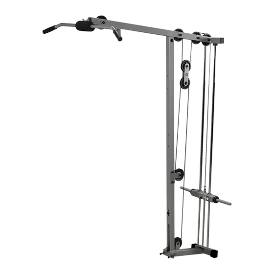
Summary of Contents for Body Solid Powerline PLA144X
- Page 1 PLA144X LAT ROW STATION Owner’s Manual WWW.BODYSOLID.COM ¡ ¢ £ ¤ ¥ ¦ ¦ § ¨ ¥ © © © ¥ ¥...
- Page 2 THERE IS A RISK ASSUMED BY INDIVIDUALS WHO USE THIS TYPE OF EQUIPMENT. TO MINIMIZE RISK, YOU MUST FOLLOW THESE RULES: Inspect equipment before each workout. Check that all nuts, bolts, screws and pop pins are in place and fully tightened. Also, before use, check cables for sign of wear. Replace all worn parts immediately.
-
Page 3: Table Of Contents
PLA144X TABLE OF CONTENTS • SAFETY INSTRUCTIONS....... PAGE 4 • PREPARATION........PAGE 5 • HARDWARE LIST........PAGE 6 • HARDWARE ILLUSTRATION....PAGE 7 • PART LIST / ILLUSTRATION....PAGE 11 • ASSEMBLY INSTRUCTIONS....PAGE 12 • EXPLODED VIEW........PAGE 20 •... -
Page 4: Safety Instructions
Keep hands, limbs, loose clothing, and long hair well description from this Owner’s Manual. Use only out of the way of all moving parts Powerline by Body Solid replacement parts when • Use care when getting on or off the unit. -
Page 5: Preparation
PLA144X PREPARATION Required tools Assembly Tips The basic tools that you must obtain before assembling Read all “Notes” on each page before beginning each step. the PLA144X include but are not limit to: While you may be able to assemble the PLA144X using the •... -
Page 6: Hardware List
PLA144X HARDWARE LIST PART # SIZE DESCRIPTION QUANTITY... -
Page 7: Hardware Illustration
PLA144X HARDWARE ILLUSTRATION Part #1 M10X75mm hex head bolt QTY. 2 Part #2 M10X70mm hex head bolt QTY. 1 Part #3 M10X65mm hex head bolt QTY. 6 Part #4 M10X40mm hex head bolt QTY. 3 Part #5 3/8”X3 1/2” allen head bolt QTY. - Page 8 PLA144X HARDWARE ILLUSTRATION CONT. Part #7 1/2” nylon lock nut QTY. 1 Part #8 3/8” nylon lock nut QTY. 1 Part #9 M10 large washer QTY. 5 Part #10 M10 small washer QTY. 2 Part #11 1/2” spring washer QTY. 1...
- Page 9 PLA144X HARDWARE ILLUSTRATION Part #12 50x50mm foot cap QTY. 3 Part #13 50X50mm end cap QTY. 4 Part #14 16mm steel bushing QTY. 8 Part #15 25X135mm rubber grip QTY. 4 Part #16 2 1/2” large donut QTY. 2...
- Page 10 PLA144X HARDWARE ILLUSTRATION CONT. Part #17 2 1/2” small donut QTY. 2 Part #18 110mm pulley QTY. 7 Part #19 6mm snap link QTY. 3 Part #20 3/4” shaft collar QTY. 2 Part #23 selector rod QTY. 1...
-
Page 11: Part List / Illustration
PLA144X PART LIST PartA PartB PartC top frame vertical frame base frame [1pcs] [1pcs] [1pcs] PartD PartE PartF top plate lat bar row bar [1pcs] [1pcs] [1pcs] PartG PartH PartI pulley plate guide rod lat bar pad [2pcs] [1pcs] [1pcs]... -
Page 12: Assembly Instructions
PLA144X STEP 1 BE CAREFUL TO ASSEMBLE ALL COMPONENTS IN THE SEQUENCE THAT THEY ARE PRESENTED. NOTE: finger tighten all hardware in this step. DO NOT wrench tighten until the last step. some components may be pre-assembled. nylon lock nuts will not fully screw onto bolts, must wrench tighten. 1A. - Page 13 PLA144X STEP 1 Above shows STEP 1 assembled and completed BACK FRAME OF YOUR PSM144X...
- Page 14 PLA144X STEP 2 BE CAREFUL TO ASSEMBLE ALL COMPONENTS IN THE SEQUENCE THAT THEY ARE PRESENTED. NOTE: finger tighten all hardware in this step. DO NOT wrench tighten until the last step. some components may be pre-assembled. nylon lock nuts will not fully screw onto bolts, must wrench tighten. 2A.
- Page 15 PLA144X STEP 2 Above shows STEP 2 assembled and completed TOP FRAME OF YOUR PSM144X...
- Page 16 PLA144X STEP 3 BE CAREFUL TO ASSEMBLE ALL COMPONENTS IN THE SEQUENCE THAT THEY ARE PRESENTED. NOTE: THIS STEP IS TO SHOW YOU WHERE THE PULLEYS NEED TO BE INSTALLED AND WHAT HARDWARE YOU WILL NEED IN ORDER TO INSTALL THEM. YOU MUST INSTALL THE PULLEYS WHILE YOU ROUTE THE CABLES.
- Page 17 PLA144X STEP 3 Above shows STEP 3 assembled and completed...
- Page 18 PLA144X STEP 4 BE CAREFUL TO ASSEMBLE ALL COMPONENTS IN THE SEQUENCE THAT THEY ARE PRESENTED. NOTE: THIS STEP IS TO SHOW YOU HOW TO ROUTE YOUR ROW BAR AND LAT BAR CABLE. YOU WILL HAVE TO INSTALL THE PULLEYS AS SEEN IN STEP 3 AND THE CABLES AT THE SAME TIME.
- Page 19 PLA144X STEP 4 Above shows STEP 4 assembled and completed...
-
Page 20: Exploded View
PLA144X EXPLODED VIEW... - Page 21 PLA144X NOTES...
-
Page 22: Contact Page
PLA144X please write your serial number in the boxes below S/N # Body-Solid ® Built for Life 1900 S. Des Plaines Ave. 1900 S. Des Plaines Ave. Forest Park, IL 60130 Forest Park, IL 60130 Phone:(708)427-3555 Phone:(708)427-3555 Fax:(708)427-3556 Fax:(708)427-3556 Hours: M-F 8:30 - 5:00 CST Hours: M-F 8:30 - 5:00 CST www.bodysolid.com Copyright 2011.
Need help?
Do you have a question about the Powerline PLA144X and is the answer not in the manual?
Questions and answers