Table of Contents
Advertisement
Quick Links
Advertisement
Table of Contents

Related Manuals for Body Solid POWERLINE PLA-200X


Summary of Contents for Body Solid POWERLINE PLA-200X
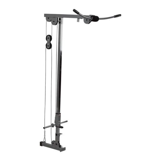
- Page 1 PLA-200X LAT ATTACHMENT Owner’s Manual WWW.BODYSOLID.COM ¡ ¢ ¡ £ ¤ ¤ ¥ ¦...
- Page 2 THERE IS A RISK ASSUMED BY INDIVIDUALS WHO USE THIS TYPE OF EQUIPMENT. TO MINIMIZE RISK, YOU MUST FOLLOW THESE RULES: Inspect equipment before each workout. Check that all nuts, bolts, screws and pop pins are in place and fully tightened. Also, before use, check cables for sign of wear. Replace all worn parts immediately.
-
Page 3: Table Of Contents
PLA-200X TABLE OF CONTENTS • SAFETY INSTRUCTIONS....... PAGE 4 • PREPARATION........PAGE 5 • HARDWARE LIST........PAGE 6 • HARDWARE ILLUSTRATION....PAGE 7 • PART LIST / ILLUSTRATION....PAGE 10 • ASSEMBLY INSTRUCTIONS....PAGE 12 • EXPLODED VIEW........PAGE 20 •... -
Page 4: Safety Instructions
Keep hands, limbs, loose clothing, and long hair well description from this Owner’s Manual. Use only out of the way of all moving parts Powerline by Body Solid replacement parts when • Use care when getting on or off the unit. -
Page 5: Preparation
PLA-200X PREPARATION Required tools Assembly Tips The basic tools that you must obtain before assembling Read all “Notes” on each page before beginning each step. the PLA-200X include but are not limit to: While you may be able to assemble the PLA-200X using the •... -
Page 6: Hardware List
PLA-200X HARDWARE LIST PART # SIZE DESCRIPTION QUANTITY... -
Page 7: Hardware Illustration
PLA-200X HARDWARE ILLUSTRATION Part #1 M12X80mm hex head bolt Qty. 2 Part #2 M12X75mm hex head bolt Qty. 1 Part #3 M12X70mm hex head bolt Qty. 3 Part #4 M10X40mm hex head bolt Qty. 7 Part #5 M12 nylon lock nut Qty. - Page 8 PLA-200X HARDWARE ILLUSTRATION CONT. Part #6 M10 nylon lock nut Qty. 7 Part #7 M12 washer Qty. 10 Part #8 110mm pulley Qty. 5 Part #9 75mm pulley Qty. 2 Part #10 2”X2” foot cap Qty. 1...
- Page 9 PLA-200X HARDWARE ILLUSTRATION CONT. Part #11 2”X2” end cap Qty. 2 Part #12 1” round end cap Qty. 2 Part #13 60X45mm nylon bushing Qty. 2 Part #14 rubber grip Qty. 4 Part #15 50X6mm rubber dount Qty. 1 Part #16 8mm snap link Qty.
-
Page 10: Part List/Illustration
PLA-200X PART LIST/ILLUSTRATION Part A Part B Part C lat bar frame base pulley frame weight frame [1pcs] [1pcs] [1pcs] Part D Part E Part F mainframe lat bar row bar [1pcs] [1pcs] [1pcs] Part G pulley plate [2pcs]... - Page 11 PLA-200X NOTES...
-
Page 12: Assembly Instructions
PLA-200X STEP 1 BE CAREFUL TO ASSEMBLE ALL COMPONENTS IN THE SEQUENCE THAT THEY ARE PRESENTED. NOTE: finger tighten all hardware in this step. DO NOT wrench tighten until the last step. some components may be pre-assembled. nylon lock nuts will not fully screw onto bolts, must wrench tighten. 1A. - Page 13 PLA-200X STEP 1 Above shows STEP 1 Above shows STEP 1 assembled and completed BASE FR BASE FRAME (PART B) FOR → PPR-200X POWER R PPR-200X POWER RACK...
- Page 14 PLA-200X STEP 2 BE CAREFUL TO ASSEMBLE ALL COMPONENTS IN THE SEQUENCE THAT THEY ARE PRESENTED. NOTE: finger tighten all hardware in this step. DO NOT wrench tighten until the last step. some components may be pre-assembled. nylon lock nuts will not fully screw onto bolts, must wrench tighten. NOTE: to make things easier later route the stamped eye end of the steel cable without the chain, through the pulley openings on the front and rear of lat bar frame (A) before...
- Page 15 PLA-200X STEP 2 REAR FRAME FOR AME FOR PPR-200X POWER RACK PPR-200X POWER R ↓ Above shows STEP 2 assembled and completed...
- Page 16 PLA-200X STEP 3 BE CAREFUL TO ASSEMBLE ALL COMPONENTS IN THE SEQUENCE THAT THEY ARE PRESENTED. NOTE: finger tighten all hardware in this step. DO NOT wrench tighten until the last step. some components may be pre-assembled. nylon lock nuts will not fully screw onto bolts, must wrench tighten. NOTE: this step is to show you where each pulley needs to be attached and what hardware goes with it.
- Page 17 PLA-200X STEP 3 Above shows STEP 3 assembled and completed...
- Page 18 PLA-200X STEP 4 BE CAREFUL TO ASSEMBLE ALL COMPONENTS IN THE SEQUENCE THAT THEY ARE PRESENTED. NOTE: finger tighten all hardware in this step. DO NOT wrench tighten until the last step. some components may be pre-assembled. nylon lock nuts will not fully screw onto bolts, must wrench tighten. 4A.
- Page 19 PLA-200X STEP 4...
-
Page 20: Exploded View
PLA-200X EXPLODED VIEW... - Page 21 PLA-200X NOTES...
-
Page 22: Contact Page
PLA-200X please write your serial number in the boxes below S/N # Body-Solid ® Built for Life 1900 S. Des Plaines Ave. Forest Park, IL 60130 Phone:(708)427-3555 Fax:(708)427-3556 Hours: M-F 8:30 - 5:00 CST www.bodysolid.com Copyright 2011. Body-Solid. All rights reserved. Body-Solid reserves the right to change design and speci cations when we feel it will improve the product. Body-Solid machines maintain several patented and patent pending features and designs.
Need help?
Do you have a question about the POWERLINE PLA-200X and is the answer not in the manual?
Questions and answers