
Related Manuals for Rose electronics Ultraview Remote 2


Summary of Contents for Rose electronics Ultraview Remote 2
- Page 1 ULTRAVIEW REMOTE 2 KVM Access Over IP INSTALLATION AND OPERATIONS MANUAL 10707 Stancliff Road Phone (281) 933-7673 Houston, Texas 77099 Internet: WWW.ROSE.COM...
- Page 2 LIMITED WARRANTY Rose Electronics warrants the UltraView Remote 2™ to be in good working order for one year from the date of purchase from Rose Electronics or an authorized dealer. Should this product fail to be in good working order at any time during this one-year warranty period, Rose Electronics will, at its option, repair or replace the Unit as set forth below.
-
Page 3: Table Of Contents
Connecting the KVM station ............................6 Connecting the Computers / Servers .......................... 7 Connecting to the network ............................7 Configuring the UltraView Remote 2 IP Input module ....................9 Logoff ..................................... 12 Restore mouse functions ............................... 12 Configuration ................................. 12 Access mode ................................. - Page 4 Figures Page Figure 1. UltraView Remote 2 Models ..........................5 Figure 2. Connecting a KVM ............................6 Figure 3. Connecting Computers ............................ 7 Figure 4. Connecting to the Network ..........................7 Figure 5. Cascading units ............................... 8 Figure 6. Configuration Menu............................9 Figure 7.
-
Page 5: Disclaimer
The UltraView Remote 2 consists of an IP input module and a KVM switch module. Each module serves a unique purpose in access control and KVM switching control. The IP input module controls the accessibility, security, and state-of-the-art encryption to the unit. -
Page 6: Features
Installation and operations manual CD Quick Start Guide Cables are usually ordered separately. If the package contents are not correct, contact Rose Electronics or your reseller so the problem can be quickly resolved. Compatibility Computers Industry standard PCs, Sun, Unix computers such as RS/6000, HP, SGI, DEC, and others. -
Page 7: Rose Electronics Web Site
Rose Electronics web site Visit our web site at www.rose.com for additional information on the UltraView Remote 2 and other products offered by Rose Electronics that are designed for data center applications, classroom environments, and many other access and switching applications. -
Page 8: System Overview
System overview The UltraView Remote 2 is a versatile and powerful product that can extend the range of access to your computers from anywhere in the world. It is designed to provide seamless and trouble-free access from any workstation on your network or any remote user to any connected computer. -
Page 9: Figure 1. Ultraview Remote 2 Models
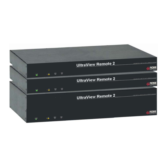
CPU (16) DB25F KVM (1) DB25F RS232 RJ12F Network RJ45F UPR-1R16UB/2 - UER-1R16UB/2 Figure 1. UltraView Remote 2 Models Note: Model part numbers UPR-xxxxx are PC / Unix models UPE-xxxxx are Multi-platform models ULTRAVIEW REMOTE 2 INSTALLATION AND OPERATIONS MANUAL... -
Page 10: Ultraview Remote 2 Installation
INSTALLATION UltraView Remote 2 Installation Installing the UltraView Remote 2 is a very easy process and should be performed by a designated administrator. The administrator will install, configure, and set-up user access profiles. A network administrator will need to assign an IP address to the unit (if needed) and set-up firewall and network access to the unit. -
Page 11: Connecting The Computers / Servers
Figure 3. Connecting Computers Connecting to the network Connect a network cable from the RJ45 connector on the rear panel of the UltraView Remote 2 and to your network (See Figure 4) Network connection Figure 4. Connecting to the Network... -
Page 12: Figure 5. Cascading Units
UltraView Pro or ServeView Pro models. The total number of cascaded units that can be added is equal to the total number of CPU ports on the unit identified as the “Master” unit. If the “Master” UltraView Remote 2 unit has 8 CPU ports, then 8 additional “Slave”... -
Page 13: Configuring The Ultraview Remote 2 Ip Input Module
UNIT CONFIGURATION Configuring the UltraView Remote 2 IP Input module When you locally connect to the UltraView Remote 2 unit for the first time the Unit and Network must be configured. Follow the recommended procedure below to configure all models: a. -
Page 14: Figure 8. Network Configuration Menu
Media Access Control address – this is the unique and unchangeable code that was hard coded within your UltraView Remote 2 unit when it was built. It consists of two 6-digit hexadecimal (base 16) numbers separated by colons. A section of the MAC address identifies the manufacturer, while the remainder is effectively the unique... -
Page 15: Figure 9. Secure Keys Encryption
Periodically, a new star character will be added to the bar as the random data are accepted as part of the new encryption key. When the bar is full, the final encryption keys for your UltraView Remote 2 will be created –... -
Page 16: Logoff
Select this option to close your current session and display the screensaver. Restore mouse functions Select this tab to revive a mouse that has ceased to function correctly. The UltraView Remote 2 provides a feature to reinstate PS/2 mouse communications. (Does not apply if using a USB mouse.) There are two main types of data formats used by current PC mice;... -
Page 17: Connecting Remotely
(NOTE: See Appendix F for additional VNC Viewer options) Click on the “Connect using built-in VNC viewer” option and the UltraView Remote 2 will install a temporary Java applet on the requesting computer and then display the connected computer’s video in the browser’s VNC viewer window. -
Page 18: User Accounts
Account #1 is the admin account. Enter User name, password. Tick/un-tick the Local and Remote options that are appropriate to the user. Allows you to modify unit settings within the UltraView Remote 2. You can define the Unit Configuration... -
Page 19: Unit Configuration
Use the arrow buttons to match the keyboard layout expected by the host system. Admin Password Enter the password that will be used to gain administrator access to the UltraView Remote 2. There can only be one admin user and only that user is given access to the configuration menus. - Page 20 A value of 0 will disable the timeout. Protocol timeout Sets the time period by which responses should have been received to outgoing data packets. If the stated period is exceeded, then a connection is considered lost and terminated. ULTRAVIEW REMOTE 2 INSTALLATION AND OPERATIONS MANUAL...
-
Page 21: Time And Date Configuration
Use the left and right arrow keys to select the correct time and date. The time entry uses the 24 hour clock notation. The internal real time clock will continue to run for roughly one week without power to the UltraView Remote 2, after that it will be lost and require resetting. -
Page 22: Network Configuration
IP Address This is the identity of the UltraView Remote 2 within a network. The IP address can be altered to suit the network it is connected on. It can either be entered manually or configured automatically using the DHCP option. When the DHCP option is enabled, this entry is grayed out. -
Page 23: Host Configuration
The Host Configuration menu allows you to configure various details for each of the host systems that may be connected to the UltraView Remote 2. Each of the 128 entries can be configured with a name, the permitted users, and the hot key combinations to switch to it. -
Page 24: Logging And Status
Appendix J. Logging and Status This screen provides various details about the user activity on the UltraView Remote 2 . Note: The log has a maximum capacity of 1000 event lines. After 1000 entries, the oldest entries are overwritten. If log data are important to your installation, ensure a regular backup procedure or use the Syslog Server IP Address option to send log information automatically to another system. -
Page 25: Kvm Switch Module Configuration
Use the up/down arrow keys to select which section menu to configure and press enter. From the Main configuration menu, use the up or down arrow keys to select (highlight) “Configure system” and press enter. The Configure system menu will display (Figure 13 ). ULTRAVIEW REMOTE 2 INSTALLATION AND OPERATIONS MANUAL... -
Page 26: Configure System
The “Expansion units” setting is the number of slave units that are connected to the master unit. This value determines which computer number is associated with which physical connector. If no expansion units are used, this number should be set to zero. ULTRAVIEW REMOTE 2 INSTALLATION AND OPERATIONS MANUAL... -
Page 27: Scan Settings
To change the delay value, select “Delay” and press enter. A list box will display showing the choices available. Use the up/down arrow keys to select the delay rate wanted and press enter. The choices are: Slow (1 second) Medium (750 ms.) Fast (500 ms.) Fastest (250 ms.) ULTRAVIEW REMOTE 2 INSTALLATION AND OPERATIONS MANUAL... -
Page 28: Configure Computers
USB keyboards for PC and Sun computers are fully supported. Save the changes when finished configuring each computer. The keyboard and mouse selections for the connected computers are: ULTRAVIEW REMOTE 2 INSTALLATION AND OPERATIONS MANUAL... -
Page 29: Configure Overlay
4 choices. Use the arrow keys to select a scheme and press enter. The choices are: Aquarium - cyan, magenta, white, and blue Tuxedo - black, red, and white Night sky - blue, black, and white Forest - green, black, cyan, and blue ULTRAVIEW REMOTE 2 INSTALLATION AND OPERATIONS MANUAL... -
Page 30: Computer Select Window
The “Computer select window” section allows you to change the background and text colors of the computer select window, and the text position on the screen. Use the up/down arrow keys to select the item to configure and press enter. DO NOT set the background and text colors the same. ULTRAVIEW REMOTE 2 INSTALLATION AND OPERATIONS MANUAL... -
Page 31: Background Color
This sets whether the computer number and computer name are displayed on the KVM stations monitor when a computer is selected. Select this item and press enter. A YES/NO box will display. Use the up/down arrow keys and select either YES or NO and press enter. ULTRAVIEW REMOTE 2 INSTALLATION AND OPERATIONS MANUAL... - Page 32 As the resolution increases, the fonts 16 x 24 classic become smaller. 16 x 32 modern The modern font is sans-serif, the classic is 16 x 32 classic similar to Times. ULTRAVIEW REMOTE 2 INSTALLATION AND OPERATIONS MANUAL...
-
Page 33: Security
The Security set-up provides an additional administrator and user access control system that is independent from the UltraView Remote 2 IP Access Module’s security system. The “Configure security” menu allows for setting a configuration password and an access password that apply to both a local user and a remote network user. The configuration password restricts access to the KVM switch module configuration menus and the access password limits access to the connected computers. -
Page 34: Remote System Operation
Prefer off - This setting will configure an un-encrypted link if the UltraView Remote 2 will allow it, otherwise it will be encrypted. Prefer on - If the UltraView Remote 2 allows it, this setting will configure an encrypted link, otherwise it will be un- encrypted. ULTRAVIEW REMOTE 2 INSTALLATION AND OPERATIONS MANUAL... -
Page 35: Vnc Viewer Toolbar
The first time you connect to the UltraView Remote 2 or switch CPU ports the cursors may be out of sync. Click on the Calibration tab on the toolbar and calibrate the Video + Mouse. - Page 36 The Remote Virtual Media feature is not implemented on this model Info When selected, this option displays an information dialog showing the current logged on users, the current host, its video mode and its mouse motion details. ULTRAVIEW REMOTE 2 INSTALLATION AND OPERATIONS MANUAL...
-
Page 37: Host Tab
CPU port are used. You can set-up a host location to display the KVM switch module’s OSD menu (+-Ctrl+-F12+Enter) but it is best to use the “Command, Keyboard” function for these types of commands. Figure 18. Host Configuration window ULTRAVIEW REMOTE 2 INSTALLATION AND OPERATIONS MANUAL... -
Page 38: Figure 19. Computer Select Window
Ctrl key, then within 2 seconds, press the Esc key. The computer select window will display listing all the computers connected to the UltraView Remote 2. This list will display the number of computers that was entered in the configure computer menu (See figure 13) Figure 19. -
Page 39: Keyboard Commands
Max computers <Ctrl> Pnnn Total ports used (all units) Units <Ctrl> Unn Number of expansion units. Width <Ctrl> Wnn Number of ports on expansion units. Keep <Ctrl> K Saves to flash memory. +-Ctrl+-k ULTRAVIEW REMOTE 2 INSTALLATION AND OPERATIONS MANUAL... -
Page 40: Troubleshooting
If both the VNC viewer and Applet login is denied access, remove power from the UltraView remote 2 for two to three seconds. This will reset the unit and unlock the IP address. If the UltraView Remote 2 unit is using DHCP, the previously assigned IP address may be changed to a different IP address when power is restored. - Page 41 Width or units command not configured properly. Reconfigure them to match number of computers and how they are connected. On-screen display not synchronized No video from computer or resolution setting not configured correctly. ULTRAVIEW REMOTE 2 INSTALLATION AND OPERATIONS MANUAL...
-
Page 42: Maintenance And Repair
This Unit does not contain any internal user-serviceable parts. In the event a Unit needs repair or maintenance, you must first obtain a Return Authorization (RA) number from Rose Electronics or an authorized repair center. This Return Authorization number must appear on the outside of the shipping container. See Limited Warranty for more information. - Page 43 Whenever it is likely that the protection has been impaired, disconnect the power cord until the ground has been restored. Servicing There are no user-serviceable parts inside these products. Only service-trained personnel must perform any servicing, maintenance, or repair. The user may adjust only items mentioned in this manual. ULTRAVIEW REMOTE 2 INSTALLATION AND OPERATIONS MANUAL...
-
Page 44: Appendix A - Specifications
Rack mount kit for 4 / 8 port units RM-UCnn Rack mount kit for 16 port unit (nnn = length in feet) (1U chassis) nn= 19”, 23”, or 24” (2U chassis) nn= 19”, 23”, or 24” ULTRAVIEW REMOTE 2 INSTALLATION AND OPERATIONS MANUAL... -
Page 45: Appendix C - Rackmount
Four 6 - 32 x 3/8” flat head mounting screws To rack mount your UltraView Remote 2 unit, attach the two rack mounting brackets to your Unit with the short flange against the Unit using the four screws provided. Secure the mounting brackets to the rack using the appropriate size bolts, nuts and lock washers. -
Page 46: Appendix E - Ip Access Control
192.168.142.64 to 192.168.142.95. The mask needed to accomplish this would be: 255.255.255.224 When you look at the mask in binary, the picture becomes a little clearer. The above mask has the form: 11111111.11111111.11111111.11100000 ULTRAVIEW REMOTE 2 INSTALLATION AND OPERATIONS MANUAL... - Page 47 In the access control list, click on the entry to be moved. Click the Up or Down buttons as appropriate. To edit/remove access control entries In the access control list, click on the appropriate entry. Click either the Edit or Remove button as appropriate. ULTRAVIEW REMOTE 2 INSTALLATION AND OPERATIONS MANUAL...
-
Page 48: Appendix F - Vnc Viewer Connection Options
Appendix F – VNC Viewer connection options When you are connecting to the UltraView Remote 2 unit using the VNC viewer, a number of options are available. Click the Options… button There are six tabbed pages of options: Color/Encoding Auto select When ticked, this option will examine the speed of your connection to the UltraView Remote 2 unit and apply the most suitable encoding method. - Page 49 Preserve Aspect Ratio When ticked, maintains a consistent ratio between the horizontal and vertical dimensions of the screen image. Inputs These feature do not apply to the UltraView Remote 2 unit installations. ULTRAVIEW REMOTE 2 INSTALLATION AND OPERATIONS MANUAL...
- Page 50 If an existing UltraView Remote 2 unit is fully reconfigured then it will need to be issued with a new identity. In this case the previous identity, listed in this tab, should be removed so that a new identity can be created on the next connection.
-
Page 51: Appendix G - Vnc Viewer Window Options
Virtual Media... This feature is not available for the UltraView Remote 2 unit New Connection... Displays the connection dialog so that you can log on to a different UltraView Remote 2 unit or VNC server location. Options... Displays the full range of connection option Connection Info... -
Page 52: Appendix H - Browser Viewer Options
Appendix H – Browser viewer options When you are connecting to the UltraView Remote 2 unit using a Web browser and the VNC applet, a number of options are available. Click the Options… button There are four options pages: Encoding and color level... -
Page 53: Appendix I - Supported Video Modes
Appendix I – Supported video modes The following video modes are supported and can be automatically configured by the UltraView Remote 2. If a recognised video mode cannot be found, the UltraView Remote 2 will gradually change some of the key parameters to discover whether a video lock can be achieved. -
Page 54: Appendix J - Hotkey Sequence Codes
“scr” and even “sc” all provide an identifiable match for “ScrollLock” whereas “en” could not be used because it might mean “Enter” or “End” (“ent” would be suitable for “Enter”). Note: Hotkey sequences and abbreviations are not case sensitive. ULTRAVIEW REMOTE 2 INSTALLATION AND OPERATIONS MANUAL... -
Page 55: Appendix K - Video Distance Capability
3- Very acceptable; Images clear, small reflections around colored letters 2- Acceptable: Slightly fuzzy images, readable text, acceptable usage for short periods of time, can cause eye fatigue. 1- Unusable; images smeared, text not easily readable. ULTRAVIEW REMOTE 2 INSTALLATION AND OPERATIONS MANUAL... - Page 56 NOTES:...
- Page 58 10707 Stancliff Road Phone: (281) 933-7673 Houston, Texas 77099 WWW.ROSE.COM...
Need help?
Do you have a question about the Ultraview Remote 2 and is the answer not in the manual?
Questions and answers