Table of Contents
Advertisement
Quick Links
KEYBOARD-MONITOR-MOUSE SWITCH WITH ON-SCREEN DISPLA Y
Installation and Operation Manua
POWER
5
SELECT
POWER
ON/OFF
1
POWER
SELECT
POWER
13
SELECT
POWER
SELECT
9
SELECT
POWER
SELECT
5
SELECT
POWER
SELECT
ON/OFF
1
POWER
SELECT
POWER
SELECT
10707 STANCLIFF ROAD n HOUSTON, TEXAS 77099 n TEL (281) 933-7673
U
LTRA
KEYBOARD-MONITOR-MOUSE SWITCH WITH ON-SCREEN DISPLAY
ON/OFF
3
1
2
SELECT
POWER
SELECT
POWER
SELECT
POWER
6
7
8
SELECT
POWER
SELECT
POWER
SELECT
POWER
2
3
4
SELECT
POWER
SELECT
POWER
SELECT
POWER
14
15
16
SELECT
POWER
SELECT
POWER
10
11
12
POWER
SELECT
POWER
SELECT
POWER
6
7
8
POWER
SELECT
POWER
SELECT
POWER
3
2
4
POWER
SELECT
POWER
SELECT
POWER
V
™
IEW
4
SELECT
POWER
KEYBOARD-MONITOR-MOUSE SWITCH WITH ON-SCREEN DISPLAY
KEYBOARD-MONITOR-MOUSE SWITCH WITH ON-SCREEN DISPLAY
l
ELECTRONICS
Advertisement
Table of Contents

Related Manuals for Rose electronics UltraView


Summary of Contents for Rose electronics UltraView
- Page 1 ™ LTRA KEYBOARD-MONITOR-MOUSE SWITCH WITH ON-SCREEN DISPLA Y Installation and Operation Manua KEYBOARD-MONITOR-MOUSE SWITCH WITH ON-SCREEN DISPLAY ON/OFF POWER SELECT POWER SELECT POWER SELECT POWER SELECT POWER SELECT POWER SELECT POWER SELECT POWER SELECT POWER KEYBOARD-MONITOR-MOUSE SWITCH WITH ON-SCREEN DISPLAY ON/OFF POWER SELECT...
- Page 3 ™ LTRA KEYBOARD-MONITOR-MOUSE SWITCH WITH ON-SCREEN DISPLA Y Installation and Operation Manua RS6000 APPLE SELECT POWER SELECT POWER SELECT POWER SELECT POWER KEYBOARD-MONITOR-MOUSE SWITCH WITH ON-SCREEN DISPLAY ON/OFF POWER SELECT POWER SELECT POWER SELECT POWER SELECT POWER SELECT POWER SELECT POWER SELECT POWER...
- Page 4 LIMITED WARRANTY Rose Electronics warrants the UltraView™ to be in good working order for one year from the date of purchase from Rose Electronics or an authorized dealer. Should this product fail to be in good working order at any time during this one year warranty period, Rose Electronics will, at its option, repair or replace the Unit as set forth below.
-
Page 5: Table Of Contents
Step 1. Connect power to the unit Step 2. Connect one computer Step 3. Connect the monitor, keyboard, and mouse Step 4. Access UltraView’s on-screen display Step 5. Verify keyboard communication Step 6. Verify mouse communication Step 7. Connect and configure the other computers Step 8. - Page 6 Miscellaneous: resolution Miscellaneous: Screen saver Miscellaneous: Screen saver wait Computer select window: Background color/Text color Computer select window: Position Computer label: Background color/text color Computer label: Position Computer label: Show computer number Computer label: fadeout Computer label: font OPERATION: COMPUTER SELECT WINDOW OPERATION: KEYBOARD COMMANDS Keyboard CPU selection Going to the next or previous CPU...
-
Page 7: Introduction
It features an on-screen display for configuration and switching computers. It is available in many different models, including UltraView and ServeView Plus with the OV-C overlay card installed. The UltraView part number is Uxy-zU where x is the platform support either E, P, S, A... -
Page 8: Getting Started
To add more CPUs to a fully populated unit, you must connect slave units to the master UltraView. To do this you need a switch to switch cable for each slave unit. By connecting 16 units each with 16 ports you can expand up to 256 computers. -
Page 9: Ultraview Hardware
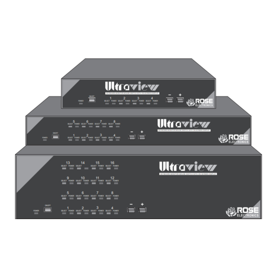
ULTRAVIEW HARDWARE The front panel The UltraView front panel has a power switch and power LED, up to 32 LEDs, and two push-button switches. To familiarize yourself with UltraView’s controls and indicators, review the illustration and descriptions given below. The unit shown below is in the L style chassis but is similar for other models. -
Page 10: The Rear Panel
The rear panel All cables are connected at the UltraView’s rear panel as shown below. The unit shown below is in the L style chassis but is similar for other models. P O WE R 1 7 VA C C T... -
Page 11: Quick Setup System Wiring Guide
QUICK SETUP SYSTEM WIRING GUIDE The following diagram offers a basic example of how to connect your CPUs, keyboard, monitor, and mouse to the UltraView unit. Connectors will vary depending upon the types of equipment being installed. Power Transformer 17 VAC CT... -
Page 12: Quick Install
Step 1. Connect power to the unit Plug the power transformer’s power jack into the the power plug located on the back of the UltraView unit, then plug the transformer into a power strip or wall outlet. Don’t turn the power on to the UltraView yet. -
Page 13: Step 4. Access Ultraview's On-Screen Display
Then exit the on-screen display by hitting escape. Step 5. Configure the PC serial mouse 5.1a If your UltraView is for PCs and Unix computers, the mouse is au- tomatically detected as PS/2 or serial. If you are using all PS/2 or all serial interfaces, then your CPUs are already configured. -
Page 14: Step 5. Verify Keyboard Communication
PS/2 mouse and a serial computer, otherwise leave it at PS/2. 6.1b If your UltraView is for Sun or Apple computers, this step does not apply, your keyboard, mouse, and CPUs are already configured and functional, skip to step 7. -
Page 15: Step 7. Connect And Configure The Other Computers
Step 7. Switching among CPU Your UltraView is now ready for operation. To take full advantage of the UltraView features, please refer to CONFIGURE VIA ON-SCREEN DISPLAY (page 12), OPERATION: COMPUTER SELECT WINDOW (page 28), and OPERATION: KEYBOARD COMMANDS (page 29). To begin switching immediately, however, follow the instructions below. -
Page 16: Ultraview Expansion
ServeViews are slave units that provide computer expansion only and perform no control functions. Slave units can be added to your UltraView system as you need them. For each slave you add to the system, you gain n-1 additional ports, where n is the number of ports on the slave unit. -
Page 17: Expansion Cable Requirements
You still need a CPU adapter cable for each CPU you will be connecting to the UltraView CPU ports. As always, one MKM adapter cable is also required for connecting the master unit to your keyboard, monitor, and mouse. -
Page 18: Configuration Via On-Screen Display
CONFIGURATION VIA ON-SCREEN DISPLAY The on-screen display is used to: Configure the UltraView through a series of configuration menus (con- trol F12 command). Switch to different computers from a window which shows a list of computer names (control escape command). You can change the color and position of this window. -
Page 19: Saving Changes Made With On-Screen Display
Maximum computers Expansion units Expansion width Scan settings Scan time (seconds) Scan mode Power on scan Keyboard typematic Rate (keys/sec) Delay Fast Detected at power-up from cable, can’t be changed here Figure 6 Configure system page ULTRAVIEW INSTALLATION AND OPERATION MANUAL... -
Page 20: Configure System: Keyboard
Sun models the keyboard type is always PC, Apple, or Sun. For the multi-platform models, the type of keyboard is automatically determined at power-up of the UltraView. If the keyboard is not attached at power-up , it will default to PC. If either a Sun or Apple keyboard is attached after power-up, it will not be recognized and you must power the UltraView off and back on for it to be recognized. - Page 21 When choosing a PS/2 mouse, this also resets the PS/2 mouse and enables data to be sent from it. This can be used after a PS/2 mouse has been connected and after the UltraView has been powered on to enable it. You can also use the reset command mentioned on page 30.
-
Page 22: Configure System: Maximum Computers
UltraView unit. To change the maximum computers, press enter while maximum computer is highlighted. An input new value box appears, see Figure 8. -
Page 23: Configure System: Expansion Width
36. Configure system: Scan time This item sets the time, in seconds, that UltraView will pause at each of the computers when scanning. The default setting is 5 seconds. To change the time, press enter while scan time is highlighted. -
Page 24: Configure System: Typematic Delay
A typematic rate input box appears. Use the arrow keys to select slow, medium, fast, or fastest and hit enter. The input box disappears and the setting selected is now shown in the typematic delay field. ULTRAVIEW INSTALLATION AND OPERATION MANUAL... -
Page 25: Configure Computers Page
Use the page up and down arrows to access computers 17-256. On models for Apple or Sun computers the keyboard and mouse type can not be changed. ULTRAVIEW INSTALLATION AND OPERATION MANUAL... -
Page 26: Configure Computers: Computer Name
When you have finished with inputting the name, hit enter. The input box disappears and the new name is then shown in the appropriate computer name field. ULTRAVIEW INSTALLATION AND OPERATION MANUAL... -
Page 27: Configure Computers: Computer Keyboard
Configure computers: Computer keyboard This field can not be changed on UltraView for Apple or Sun models. For the PC and multi-platform models you can assign which type of keyboard interface is used. To change the computer keyboard type, press enter while a keyboard field is highlighted. -
Page 28: Configure Computers: Computer Mouse
Configure computers: Computer mouse This field can not be changed on UltraView for Apple or Sun models. This field can also not be changed if the keyboard type is set to Apple, because the UltraView will automatically assume a mouse type of Apple. For PCs you can assign which type of mouse is used. -
Page 29: Configure Overlay Page
Miscellaneous: resolution This item controls what resolution of video is sent to the monitor when no computer video is present. This gives maximum flexibility as to what type of ULTRAVIEW INSTALLATION AND OPERATION MANUAL... -
Page 30: Miscellaneous: Screen Saver
Miscellaneous: Screen saver The UltraView features a screen saver feature which reduces the wear on your screen and provides security for your system. When there has been no keyboard or mouse activity for a specified length of time (set by the screen saver time command below), the screen saver turns on. -
Page 31: Computer Select Window: Background Color/Text Color
The name of the color is also shown with its color changing as you point to each different color, so an example of the color can be seen. Hit enter to select the color pointed to. The input box ULTRAVIEW INSTALLATION AND OPERATION MANUAL... -
Page 32: Computer Label: Position
An input new value box appears. Use the numeric keys to input a new value from 0 to 255 seconds and hit enter. The input box disappears and the new value is then shown in the computer label fadeout field. ULTRAVIEW INSTALLATION AND OPERATION MANUAL... -
Page 33: Computer Label: Font
To change the font, press enter while font is highlighted. A font input box appears. Use the arrow keys to select the desired font and hit enter. The input box disappears and the setting selected is now shown in the font field. ULTRAVIEW INSTALLATION AND OPERATION MANUAL... -
Page 34: Operation: Computer Select Window
When switching to the new computer, the name of the new computer will show in its previously configured position, color, and font. ULTRAVIEW INSTALLATION AND OPERATION MANUAL... -
Page 35: Operation: Keyboard Commands
(such as 01) or enter the single-digit number and press <Enter>. If you enter only one digit, and do not follow it with <Enter>, UltraView will wait two seconds for you to enter another digit, then, if no additional number is entered, will switch immediately to the single-digit CPU. -
Page 36: Display Label Command
Reset command This command is used to re-boot the mouse and keyboard without removing power from the UltraView. This is most useful to reset a PS/2 mouse which has been unplugged and plugged back in. This command is also useful to enable mouse data to be sent to a CPU which has not enabled the mouse. -
Page 37: Video
This table applies to the base unit without chaining. There will be some degradation when UltraViews are chained together. Rose Electronics does not support systems where the video quality is 1 or 2. There are further capabilities not listed here in order to send the higher resolution video longer distances. - Page 38 1 – Unusable; images smeared; text not easily readable Table 4. Video distance capability 5’ 10’ 20’ 30’ 50’ 75’ 100’ 125’ 150’ 200’ 640X480 60Hz refresh 640X480 72-75Hz refresh 800X600 non-interlaced 1024X768 interlaced 1024X768 non-interlaced 1280X1024 interlaced 1280X1024 non-interlaced ULTRAVIEW INSTALLATION AND OPERATION MANUAL...
-
Page 39: Miscellaneous
UltraView unit is designed to accept rack mount brackets that attach to the sides of the UltraView unit. There are three sizes available 19" by 1.75", 23" by 1.75", and 24" by 1.75". You must order the rack mount kit for the correct chassis. -
Page 40: Upgrading The Flash Memory
2. Press both the - and + switches on the front panel, at power-on of the UltraView. The UltraView is ready to accept the upgrade file at 9600 baud as shown by LED 1 being lit. To use 57600 baud, press the + switch, LED 4 will light. - Page 41 2. Press both the - and + switches on the front panel, at power-on of the UltraView. The UltraView is ready to accept the upgrade file at 9600 baud as shown by LED 1 being lit. To use 57600 baud, press the + switch, LED 4 will light.
-
Page 42: Keyboard Command Summary
The <Ctrl> character is always passed through to the CPU. The command characters and command operands, however, are absorbed by the UltraView and not sent to the CPU. Table 7. Keyboard command summary Command... -
Page 43: Troubleshooting
CPU keyboard and mouse not configured. 2. Mouse driver does not load. a. If PS/2 type mouse, CPU must be connected to UltraView or mouse at boot-up time in order for mouse to be recognized by CPU. Re- boot computer with UltraView powered on and cable attached. - Page 44 Cable is defective, try using cable from another CPU if problem goes away cable is defective. f. Port on UltraView is defective, try using another port on UltraView. If problem goes away port is defective. 10. Lower resolution video OK, but can’t enter high resolution mode a.
-
Page 45: Service Information
Support Department. Reset to factory default To reset the UltraView to its factory default settings hold the – switch in at power up. Keep it pressed in until the unit switches to the last port on the unit, port 4 (on a 4-port unit), port 8 (on an 8-port unit), and so on. If the monitor is connected, various diagnostic messages will appear. -
Page 46: Appendix A. Cpu/Mkm Pinout Specification
Audio in/out Audio (Multi-platform only) Audio in/out Audio in/out Audio (Multi-platform only) Audio in/out Audio in/out Audio (Multi-platform only) Unreg -12V Ground Ground Digital Ground Ground Ground Digital Ground Unreg +12V RS232-in RS232-out Serial Data ULTRAVIEW INSTALLATION AND OPERATION MANUAL... -
Page 47: Appendix B. Rs232 Pinout Specifications
17VAC CT, 700ma H (high) 17VAC CT, 1400ma CPU/MKM CONNECTORS DB25 Female CHASSIS Fully shielded, black painted steel CONTROLS Power switch, - switch, + switch INDICATORS 1 power LED, 4-16 select LED, 4-16 CPU power LED ULTRAVIEW INSTALLATION AND OPERATION MANUAL... -
Page 48: Appendix D. Factory Default Settings
Computer select window X=3 Y=3 Position Computer label Transparent magenta Background color Computer label Yellow Text color Computer label X=3 Y=90 Position Show computer number Fade out 20 seconds Font 16x32 classic Caps/Numlock/Scroll Numlock On ULTRAVIEW INSTALLATION AND OPERATION MANUAL... -
Page 49: Part Number
CAB-C1AV0400Mxx Coax Sun CPU video keyboardmouse to DB-25M CAB-SC0800Cxx** Other cables 4-conductor RJ11 cable to connect PC to UltraView’s RS232 CAB-04RJxx* serial port. Used with DB25 or DB9 adapter shown below. 25 pin female DB25 adapter for UltraView serial port... - Page 52 ELECTRONICS 10707 STANCLIFF ROAD n HOUSTON, TEXAS 77099 n TEL (281) 933-7673...
Need help?
Do you have a question about the UltraView and is the answer not in the manual?
Questions and answers