Advertisement
Advertisement
Table of Contents

Related Manuals for Body Solid G4I


Summary of Contents for Body Solid G4I
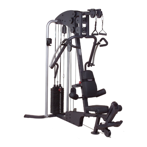
- Page 1 Body-Solid ® A s s e m b l y I n s t r u c t i o n s...
- Page 2 S T E P Be careful to assemble all components in the sequence they are presented. NOTE: Finger tighten all hardware in this step. Do Not wrench tighten until end of step 3. Attach two Foot Caps (4) to Rear Base Frame (B) as shown. Attach Main Base Frame (A), Flat Plate (114) and Guide Rods (E) to Rear Base Frame (B) using: Two 50 (3/8”...
- Page 3 S T E P USE THE TWO WEIGHT STACK RISERS (38) FOR A 160lb. WEIGHT STACK. IF YOU HAVE A 210lb. WEIGHT STACK OMIT THE TWO WEIGHT STACK RISERS (38). RED DOT...
- Page 4 S T E P Be careful to assemble all components in the sequence they are presented. NOTE: Finger tighten all hardware in this step. Do Not wrench tighten until end of step 3. Slide Weight Stack Plates (37)* onto Guide Rods (E). Make sure the opening in each Weight Stack Plate (37), for the Weight Stack Pin (60), is facing forward.
- Page 5 S T E P RED DOT YELLOW...
- Page 6 S T E P Be careful to assemble all components in the sequence they are presented. Attach two Top Panels (G) to Rear Arch Post (F) and install Pulley (17) using: Two 46 (3/8” x 4 1/4” hex head bolt) One 7 (5/8”...
- Page 7 S T E P...
- Page 8 S T E P Be careful to assemble all components in the sequence they are presented. Attach Right Seated Press Arm (K) and Left Seated Press Arm (L) to Vertical Frame (J) With Shaft (128) using: Two 39 (1/2” x 3/4” hex head bolt) Two 73 (1/2”...
- Page 9 S T E P marked with R and a YELLOW marked with L and a RED dot...
- Page 10 S T E P Be careful to assemble all components in the sequence they are presented. Attach two Leg Hold Downs (Q) and (R) to Vertical Frame (J) using: Two 46 (3/8” x 4” hex head bolt) Four 74 (3/8” washer) Two 72 (3/8”...
- Page 11 S T E P...
- Page 12 S T E P Be careful to assemble all components in the sequence they are presented. Seat Pad Frame (AA) is pre-installed into Front Base Frame (C). Attach two Foam Rollers (21) to Seat Pad Frame (AA) using Foam Roller Bar (X). Hold Foam Rollers (21) in place with Plastic Washer (13) on the inside and Roller End Cap (9) on the outside as shown.
- Page 13 S T E P...
- Page 14 S T E P Be careful to assemble all components in the sequence they are presented. Insert End Cap (3) to the top of Leg Extension (W). Attach Leg Extension (W) to the Front Base Frame (C) with Shaft (126) and the pre-installed hardware: Two 83 (5/16”...
- Page 15 S T E P REVERSE SIDE DRAWING...
- Page 16 S T E P Be careful to assemble all components in the sequence they are presented. Insert Wide Pulley (20) into Leg Extension (W) and hold in place using: One 51 (3/8” x 2 3/4” hex head bolt) Two 74 (3/8” washer) One 72 (3/8”...
- Page 17 S T E P...
- Page 18 S T E P Be careful to assemble all components in the sequence they are presented. Weight Stack Cable (32) Stamped Eye End Metal Ball End 2670mm 8’ 9” Attach Weight Stack Cable (32) between Top Side Panels (G) using: One 48 (3/8”...
- Page 19 S T E P Diagram 1 Cable Installation Start by attaching the Cable (32) between the Top Side Panels (G) here. Weight Stack Cable Diagram 2 Pulley Installation...
- Page 20 S T E P Be careful to assemble all components in the sequence they are presented. Weight Stack Cable (32) Stamped Eye End Metal Ball End 2670 mm 8’ 9” Route Cable (32) up and around pre-installed Pulley (A5). Leave Cable (32) hanging down toward the weight stack.
- Page 21 3 1/2” diameter pulley S T E P Diagram 1 Cable Installation Start here by routing the Cable (32) over Pulley (A4). WA R N I N G Selector Rod Top Bolt (101) must be threaded a minumum of 1/2” into the Selector Rod (23), and Jam Nut (70) tightened securely against spring lock washer (76) to ensure proper connection.
- Page 22 S T E P Be careful to assemble all components in the sequence they are presented. High Pulley Cable (29) Ball Stop End Ball Stop End 6925 mm 22’ 8” Slide Oilite Washer (107) onto the top of Vertical Frame (J) as shown in Diagram 2. Attach Pivoting Pulley Holder (BD) onto the right side of Vertical Frame (J) using: One 105 (1/2”...
- Page 23 S T E P Diagram 1 Cable Installation Start by routing cable through the Pivoting Pulley Holder (BD). High Pulley Cable Diagram 2 Pulley Installation...
- Page 24 S T E P Be careful to assemble all components in the sequence they are presented. High Pulley Cable (29) Ball Stop End Ball Stop End 6925 mm 22’ 8” Route Cable (29) over the top and around pre-installed Pulley (B8) and toward the Left Seated Press Arm (L).
- Page 25 S T E P Diagram 1 Cable Installation High Pulley Cable Start here by routing Cable (29) around Pulley (B7) here. Diagram 2 Pulley Installation...
- Page 26 S T E P Be careful to assemble all components in the sequence they are presented. Leg Extension Cable (30) Ball Stop End Threaded End 4455 mm 14’ 7” Route the threaded end of the Leg Extension Cable (30) under pre-installed Pulley (C1) and through Leg Extension (W).
- Page 27 S T E P Diagram 1 Cable Installation Leg Extension Cable Start here at Leg Extension station by inserting the threaded end here. Diagram 2 Pulley Installation 3” diameter pulley...
- Page 28 S T E P Be careful to assemble all components in the sequence they are presented. Leg Extension Cable (30) Ball Stop End Threaded End 14’ 7” 4455 mm See Diagram 1. Connect the Threaded End of Cable (30) to Single Pulley Holder (BE). * *Note: Make sure Cable (30) is threaded a minimum of 1/2”...
- Page 29 S T E P Short Cable Diagram 1 Diagram Cable Installation Cable Installation Short Cable-A Leg Extension Cable Short Cable-B Diagram 2 Pulley Installation...
- Page 30 Cable(s) are sloppy and there is no resistance from the weight stack for the first few inches of the exercise. There are Three areas for cable adjustment on the G4I: A. Selector Rod Top Bolt (101) B. Adjustments in Double Pulley Bracket (BB).
- Page 31 S T E P Turn and loosen Rubber Stops (108) to take up space and tighten cable. Loosen Turn and loosen Rubber Stop (108) to take up space and tighten cable. Loosen WA R N I N G Selector Rod Top Bolt (101) must be NOTE 1 threaded a minimum of 1/2”...
- Page 32 G 4 I M a i n f r a m e P a r t s L i s t KEY# QTY PART# DESCRIPTION JG4IMBF-A MAIN BASE FRAME JG4IRBF-B REAR BASE FRAME JG4IFBF-C FRONT BASE FRAME JG4ILSP-D LOW SIDE PANELS JG4IGR-E GUIDE RODS JG4IRAP-F...
- Page 33 G 4 I H a r d w a r e L i s t KEY# QTY PART# DESCRIPTION JCEC22X1.8 CONVEX END CAP 2” X 2” (1.8” THICK) JCEC22X2.5 CONVEX END CAP 2” X 2” (2.5” THICK) JCEC23 CONVEX END CAP 2” X 3” JFC23 FOOT CAP 2”...
- Page 34 G 4 I H a r d w a r e ( c o n t i n u e d ) KEY# QTY PART# DESCRIPTION JSCH.18X22 STEEL CHAIN 3/16” X 22” JCES CABLE END SHAFT 1/2” JAM NUT JLN.5 JNLN.5 1/2”...
- Page 35 G 4 I H a r d w a r e ( c o n t i n u e d ) KEY# QTY PART# DESCRIPTION SH.31X.75FTB SOCKET HEAD BOLT 5/16” X 3/4” FULL THREAD FRAME LEVELER JPAH PRESS ARM HOLDERS JWSW.37 3/8”...
- Page 36 E X P L O D E D V I E W D I A G R A M G 4 I...
- Page 37 © Copyright 2003. Body-Solid. All rights reserved. Body-Solid reserves the right to change design and specifications when we feel it will improve the product. Body-Solid machines maintain several patented and patent pending features and designs. All rights reserved on all design patents and utility patents.
Need help?
Do you have a question about the G4I and is the answer not in the manual?
Questions and answers