Advertisement
Item # XXX-XXX XXX-XXX XXX-XXX
Model # 52371 52372 52379
UL Model # 52-RMG
USE AND CARE GUIDE
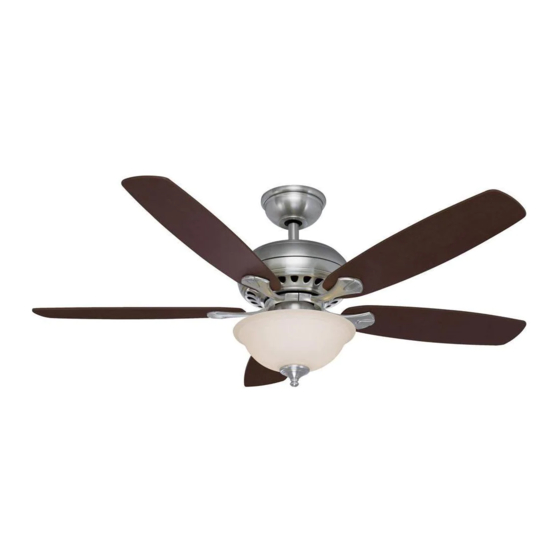
SOUTHWIND 52-INCH CEILING FAN
Questions, problems, missing parts? Before returning to the store call
Hampton Bay Customer Service
8 a.m. - 6 p.m., EST, Monday-Friday
1-877-527-0313
HAMPTONBAY.COM
THANK YOU
We appreciate the trust and confidence you have placed in Hampton Bay through the purchase of this ceiling fan. We strive to continually create
quality products designed to enhance your home. Visit us online to see our full line of products available for your home improvement needs.
Thank you for choosing Hampton Bay!
Advertisement
Table of Contents

Subscribe to Our Youtube Channel
Related Manuals for HAMPTON BAY SOUTHWIND 52371


Summary of Contents for HAMPTON BAY SOUTHWIND 52371
- Page 1 THANK YOU We appreciate the trust and confidence you have placed in Hampton Bay through the purchase of this ceiling fan. We strive to continually create quality products designed to enhance your home. Visit us online to see our full line of products available for your home improvement needs.
-
Page 2: Table Of Contents
Table of Contents Table of Contents ............2 Assembly ............... 7 Safety Information ............2 Operating Your Fan and Remote Control ....12 Warranty ................. 3 Care and Cleaning ............13 Pre-Installation .............. 3 Troubleshooting ............14 Installation ..............6 Safety Information To reduce the risk of electric shock, ensure the WARNING: To reduce the risk of personal injury,... -
Page 3: Warranty
A certain amount of “wobble” is normal and should not be considered a defect. Servicing performed by unauthorized persons shall render the warranty invalid. There is no other express warranty. Hampton Bay hereby disclaims any and all warranties, including but not limited to those of merchantability and tness for a particular purpose to the extent permitted by law. - Page 4 Pre-Installation (continued) HARDWARE INCLUDED NOTE: Hardware not shown to actual size. Part Description Quantity Part Description Quantity Blade attachment hardware Balancing kit Plastic wire connector Extra plastic plug (to be used Hanger pin for fan without light kit) Locking pin Extra blade bracket hardware ( screw and lockwasher) Close-to-ceiling mount...
-
Page 5: Package Contents
Pre-Installation (continued) PACKAGE CONTENTS Part Description Quantity Part Description Quantity Slide-on mounting bracket Blade (inside the canopy) Blade bracket ( ange), screws Ball/downrod assembly pre-installed Canopy with canopy ring Glass bowl attached Light bulbs, 60-Watt maximum Fan-motor assembly Hand unit/receiver Light kit tter assembly (battery included IMPORTANT: This product and/or components are... -
Page 6: Installation
Installation MOUNTING OPTIONS WARNING: To reduce the risk of re, electric shock, or NOTE: You may need a longer downrod to maintain proper personal injury, mount the fan to an outlet box marked blade clearance when installing on a steep, sloped ceiling. acceptable for fan support using the screws provided with the The maximum angle allowable is 30°... -
Page 7: Assembly
Assembly – Standard Ceiling Mounting Preparation for mounting Routing the wires Remove the canopy ring from the canopy (C) by turning the Route the wires exiting the top of the fan motor (D) and ring to the right until it unlocks. through the canopy ring (C). -
Page 8: Hanging The Fan
Assembly -Close-To-Ceiling Mounting Remove canopy ring from the canopy (C) by turning the ring to the right until it unlocks. Remove the mounting bracket (A) from the canopy (C) by loosening the four screws on the top of the canopy (C). Remove the two non-slotted screws and loosen the slotted screws. - Page 9 Assembly – Hanging the Fan (continued) Making the electrical connection Mounting the fan WARNING: When using the standard ball/downrod IMPORTANT: Use the wire connecting nuts supplied with mounting, the tab in the ring at the bottom of the mounting your fan. Secure the connectors with electrical tape and bracket must rest in the groove of the hanger ball.
- Page 10 Assembly – Attaching the Fan Blades Attaching the blades to the blad Fastening the blade assemblies to brackets the motor Attach a blade (F) to a blade bracket (G) by inserting Fasten the blade assembly to the motor (D) by inserting the screws (AA) into the holes in the blade and through the alignment post into the slot on the bottom of the motor and blade bracket.
- Page 11 Assembly – Attaching the Accessories Installing the bulbs and attaching Attaching the light kit tter assembly the glass bowl Loosen the three screws on the switch cup cover of the Remove the rubber washer, hex nut, bottom cover and nial light kit tter assembly (E).
-
Page 12: Operating Your Fan And Remote Control
Assembly – Assembling the Fan Without the Light Kit Assembling the fan without the light In order to use the fan without the light kit, remove the switch cup cover from the top of the light kit tter assembly (E) by removing the center hex nut inside the switch cup cover, and then thread the switch cup cover off of the threaded nipple on the top of the light kit tter assembly (E). -
Page 13: Care And Cleaning
Operating Your Fan and Remote Control (Continued) Setting the code A. Wire Connection: Fan Green Wire..........Bare Supply Wire Red Receiver Wire (AC IN L)......Black Supply Wire White Receiver Wire (AC IN N)......White Supply Wire White Receiver Wire (TO MOTOR N)....White Fan Wire Black Receiver WIre (TO MOTOR L)....Black Fan Wire Blue Receiver Wire (FOR LIGHT)......Blue Light Wire NOTE: If other fan wires are a different color, have this unit... -
Page 14: Troubleshooting
Troubleshooting Problem Solution The fan will not start Check the main and branch circuit fuses or breakers. Check the line wire connections to the fan and switch wire connections in the switch housing. Check battery in transmitter. Ensure you are in the normal range of 10-20 feet. Ensure the dip switches settings are in the same on the transmitter and receiver. - Page 15 This page intentionally left blank.
- Page 16 Questions, problems, missing parts? Before returning to the store call Hampton Bay Customer Service 8 a.m. - 6 p.m., EST, Monday-Friday 1-877-527-0313 HAMPTONBAY.COM Retain this manual for future use. X0000000000-A...
Need help?
Do you have a question about the SOUTHWIND 52371 and is the answer not in the manual?
Questions and answers