Table of Contents
Advertisement
Available languages
Available languages
Item #1006 022 993
Safety Information
Model #76278
Read and save these instructions
WARNING: To avoid possible
electrical shock, turn the
electricity off at the main
fuse box before wiring. If you
feel you do not have enough
electrical wiring experience,
INSTALLATION AND OPERATION
contact a licensed electrician.
CAUTION: Incorrect wire
SMART WI-FI REMOTE CONTROL
connections will damage
this receiver.
CAUTION: To reduce the risk
of fire or injury, do not use this
product in conjunction with any
variable (rheostat) wall control.
NOTE: The battery will weaken
with age and should be
replaced before leaking takes
place as this will damage
the hand unit. Dispose of the
used battery properly, keep
the battery out of the reach of
children.
Warranty
The supplier warrants the remote control and receiver to be free from defects in
workmanship and material present at time of shipment from the factory for a period of
one year after the date of purchase by the original purchaser. We agree to correct such
defects without charge or at our option replace with a comparable or superior model if
the product is returned. To obtain warranty service, you must present a copy of the
receipt as proof of purchase. All costs of removing and reinstalling the product are your
responsibility. Damage to any part such as by accident or misuse or improper installation
or by affixing any accessories, is not covered by this warranty. Servicing performed by
unauthorized persons shall render the warranty invalid. There is no other express warranty.
Home Depot hereby disclaims any and all warranties, including but not limited to those of
merchantability and fitness for a particular purpose to the extent permitted by law. The
Questions, problems, missing parts? Before returning to the store,
duration of any implied warranty which cannot be disclaimed is limited to the time period
call Hubspace Customer Service
as specified in the express warranty. Some states do not allow a limitation on how long an
8 a.m. - 7 p.m., EST, Monday - Friday, 9 a.m. - 6 p.m., EST, Saturday
implied warranty lasts, so the above limitation may not apply to you. The retailer shall not
1-877-592-5233
be liable for incidental, consequential, or special damages arising out of or in connection
HOMEDEPOT.COM/HUBSPACE
with product use or performance except as may otherwise be accorded by law. Some
states do not allow the exclusion of incidental or consequential damages, so the above
exclusion or limitation may not apply to you. This warranty gives specific legal rights, and
We appreciate the trust and confidence you have placed in Hampton Bay through
you may also have other rights which vary from state to state. This warranty supersedes all
the purchase of this remote control. We strive to continually create quality
prior warranties. Shipping costs for any return of product as part of a claim on the warranty
products designed to enhance your home. Visit us online to see our full line of
must be paid by the customer.
products available for your home improvement needs.
Contact the Customer Service Team at 1-877-592-5233 or visit HomeDepot.com/hubspace.
Thank you for choosing Hampton Bay!
Installation (continued)
Installation (continued)
4
Wiring the receiver to the household wiring
5
Wiring the fan to the receiver
WARNING: To avoid possible electrical shock, turn the electricity off at the
IMPORTANT: Use the wire connecting nuts (C) supplied with your remote.
main fuse box before wiring. If you feel you do not have enough electrical
The wire connecting nut (C) for the ground/green wire is supplied with the
wiring knowledge or experience, contact a licensed electrician.
fan. Secure the connectors with electrical tape and ensure there are no
loose strands or connections.
WARNING: Each wire nut supplied with this fan is designed to accept up
to one 12-gauge house wire and two wires from the fan. If you have larger
• Connect the fan motor white wire
than 12-gauge house wiring or more than one house wire to connect to
the fan wiring, consult an electrician for the proper size wire nuts to use.
to the receiver white wire using a
wire connecting nut (C).
IMPORTANT: Use the wire connecting nuts (C) supplied with your remote.
• Connect the fan motor black wire
The wire connecting nut (C) for the ground/green wire is supplied with the
fan. Secure the connectors with electrical tape and ensure there are no
to the receiver black wire using a
loose strands or connections.
wire connecting nut (C).
• Connect the fan motor blue wire
• Spread the wires apart so that the green and white wires are on one side of the
to the receiver blue wire using a
outlet box and the black wire is on the other side.
wire connecting nut (C).
• Connect the green fan wires to the household ground wire (this may be a green
• Secure each wire connecting nut
or bare wire) using a wire connecting nut (C) supplied by your fan.
using electrical tape.
• Connect the receiver black (or red) wire to the household black (hot) wire using
• Turn the wire connecting nut (C)
a wire connecting nut (C).
upward and push the wiring into
• Connect the receiver white wire to the household white wire (neutral) wire
the outlet box (MM).
using a wire connecting nut (C).
• Secure each wire connecting nut using electrical tape.
1
Mounting the transmitter to the wall
• Slide the screw cover plate up to remove it from the wall cradle (F).
Outlet Box
• Position the wall cradle (F) in the desired position and attach it to the wall using the
included wall cradle screws (G).
C (x3)
• Slide the screw cover plate back onto the wall cradle to conceal the screws.
Green (or Bare)
NOTE: Plastic anchors (H) are included for extra support. The included screws (G)
Black
are designed to screw easily into the wall. If you would like a more permanent
White
Green
or secure hold, install the wall anchors (H) prior to attaching the wall cradle to
Black
the wall.
Receiver
Antenna
Screw cover plate
DIP
WIFI
Antenna
Receiver (B)
Pre-Installation
TOOLS REQUIRED
1. The power supply to the remote control
receiver should be connected through a
mains switch, i.e. existing wall switch.
2. Disconnect from power supply at breaker
box or wall switch before working on
remote control receiver or ceiling fan.
3. Install receiver into the mounting
bracket/ canopy of the fan to ensure
proper protection.
Phillips
Electrical tape
4. This unit is to be used for the control of
screwdriver
ceiling fan and in a AC110/120V 60Hz
power supply only.
5. Do not install in damp locations or
immerse in water. (For indoor use only.)
6. Do not pull on or cut leads shorter.
7. Do not drop or bump the unit.
PACKAGE CONTENTS
8. Do not mix old and new batteries.
9. Do not mix alkaline, standard (carbon-
zinc), or rechargeable (ni-cad, ni-mh,
etc.) batteries.
A
IMPORTANT: This product and/
or components are governed by
one or more of the following U.S.
Patents: 5,947,436; 5,988,580;
6,010,110; 6,046,416, 6,210,117
and other patents pending.
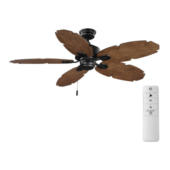
Operating Your Remote Control
1
Operating the remote control
Power ON/OFF: Press and release the power
button to turn the fan and light on or off.
Fan speed: LEDs on the fan speed button will
illuminate to the corresponding speed.
Outlet box
Press and release 1 time: turns the fan speed
in the ceiling
to 4.
(MM)
Press and release 2 times: turns the fan
Green
speed to 3.
Press and release 3 times: turns the fan
speed to 2.
Press and release 4 times: turns the fan
speed to 1.
ON DIP
1 2 3 4
Press and release 5 times: turns the fan off.
Light ON/OFF:
Blue Black White
Press and release the button to turn the light
on or off.
Press and hold the button to activate the
C (x3)
dimmer function.
Comfort Breeze: Press the button to enable
Comfort Breeze; this will change your fan
randomly, simulating a relaxing breeze. To
cancel this features press fan speed button or
power button.
Timer:
While the fan is on press 1 time-turns on a 2 hour run timer.
While the fan is on press 2 times-turns on a 4 hour run timer.
While the fan is on press 3 times-turns on a 8 hour run timer.
G
F
Installation
1
Setting the code on the remote control
NOTE: The frequencies on your receiver and hand unit have been preset
at the factory. Before installing the receiver, make sure the dip switches
on the receiver and hand unit are set to the same frequency. The dip
switches on the hand unit are located inside the battery compartment.
NOTE: The switch marked "O/D" controls the dimming function of the
lights. If you are using non-dimmable bulbs, use a ballpoint pen or small
screwdriver to set the switch to "O" to disable the dimming function.
If you are using dimmable bulbs, set the switch to "D" to enable the
dimming function.
Wire
Step
cutter
ladder
NOTE: The battery will weaken with age and should be replaced before
leaking takes place, as battery leakage damages the hand unit. Dispose
of the used battery properly and keep the battery out of the reach of
children.
• Remove the remote control (B)
battery cover by pressing firmly
on the arrow and sliding the
cover off.
• Slide the dip switches (ZZ) to
C
your choice of either up or down.
The factory setting is up.
• Slide the dip switches (ZZ) on
D
D
O
the receiver (H) to the same
position as set on the remote
control (B).
• Install two 1.5V batteries
B
(included).
• Replace the battery cover on the
E
remote control (B).
• Insert the silicone rubber
stopper (E) into the hole on the
receiver (A) to cover the dip
switches.
A
Part
Description
Quantity
A
Receiver
1
B
Remote control
1
C
Wire connecting nut
5
D
AAA battery (1.5V)
2
E
Silicone rubber plug
1
F
Wall cradle
1
G
Wall cradle screw
2
H
Plastic anchor
2
I
Rubber isolated pad
2
Controller model: TR240B
Application Set-Up
1
Getting started
□ Download the Hubspace™ app from the App Store or
the Google Play Store to your mobile device.
□ Launch the app.
□ To register, enter your email address and a password.
Or, login if you already have an account.
□ Bluetooth access is required for device setup.
2
Verify your network
□
Hubspace only shows WiFi networks that your device can use. Check your network
only if an option does not appear during set up.
□
This Hubspace device requires a 2.4GHz Wi-Fi channel.
□
Most routers provide a 2.4 GHz WiFi channel.
□
If you do not see your Wi-Fi network name when you attempt to connect your
device, please check your router settings.
3
Add a device
□ In the Hubspace app, tap the plus sign in the upper right corner.
□ Scan your product's QR code. You can find a copy of the QR code on the device itself
and in the Quick Start Guide.
Scan problem?
If the QR code cannot be scanned for some reason, you can enter the code manually.
Tap Enter Code and follow the instructions.
□ Connect your device to power and follow the instructions on screen.
(For lighting and fan products only)
If you are unable to access the QR code for your light, you can put it into discovery mode
with the following sequence:
□ Switch the device off and on 5 times. The light will pulse to show that it can now be
discovered.
□ In the Hubspace app, tap the plus sign in the upper right corner and follow the
instructions to discover devices. More than one device can be added at a time using
this method.
4
Set up your voice assistant
□ In the Hubspace app, tap the Hubspace button.
□ Select the Integrations tab, choose your voice assistant and follow the instructions.
NOTE: For more information on smart remote set up, please refer to the quick start
guide located in the remote pack.
Installation (continued)
2
Installing the rubber isolated pads
• Loosen the two screws provided with the outlet box; insert two rubber
isolatedpads (I) between the mounting bracket and the outlet box; firmly
tightened the two screws.
D
O
ZZ
B
ON
1
2
3
4
Voice Commands
The Smart Wi-Fi Remote Control works with Alexa and Google Assistant.
This section lists some of the voice commands you can use. To view these and other
commands, go to http://hubspaceconnect.com/.
Alexa
When you
Ask Alexa to...
Ask Google to...
want to...
Turn on the fan
... turn on <device name> fan
... turn on <device name> fan power.
power.
only.
Turn off the fan
... turn off <device name> fan
... turn off <device name> fan power.
power.
only.
Turn on the light
... turn on <device name> light
... turn on <device name> light power.
power.
only.
Turn off the light
... turn off <device name> light
... turn off <device name> light power.
only.
power.
Change the
... Set <device name> brightness
... Set <device name> brightness
brightness.
to 75%.
to 75%.
... Set <device name> light to 25%.
... Set <device name> light to 25%.
... Make <device name> dimmer.
... Brighten <device name>.
... Make <device name> brighter.
... Dim <device name>.
... Dim <device name>.
... Brighten <room name>.
... Brighten <device name>.
... Dim <room name>.
... Dim <group name>.
... Brighten <group name>.
Change the White
... Change <device name> to Cool
... Change <device name> to Ivory.
Temperature.
White.
... Change <device name> to Daylight.
... Change <device name> to Warm
... Change <device name> to Cool
White.
White.
... Change <device name> to
... Change <device name> to Warm
Daylight White.
White.
... Change <device name> to White.
... Change <device name> to
Incandescent.
Change the fan
... Set <device name> speed to
... Set <device name> speed to
speed.
fastest.
fastest.
... Set <device name> speed to fast.
... Set <device name> speed to fast.
... Set <device name> speed to
... Set <device name> speed to
medium.
medium.
... Set <device name> speed to
... Set <device name> speed to slow.
slow.
... Increase <device name> speed.
... Increase <device name> speed.
... Decrease <device name> speed.
... Decrease <device name> speed.
Turn on Comfort
... Turn on Comfort Breeze on
... Turn on Comfort Breeze on <device
Breeze.
<device name>
name>
Installation (continued)
3
Installing the receiver
WARNING: To reduce the risk of fire or electric shock, remember to
disconnect power. The electrical wiring must meet all local and national
electrical code requirements. The electrical source and fan must be 110/120
volt, 60Hz. Do not use this product in conjunction with any variable wall
control. Incorrect wire connection can damage this receiver.
CAUTION: If fan or house wires are a different color, have this unit installed by a
licensed electrician.
CAUTION: Do not install in a damp location or immerse in water (for indoor use
only). Do not pull on or cut leads shorter. Do not drop or bump the unit.
NOTE: You must set ceiling fan to high speed and light kit (if any) to the
on position using the pull chains (if applicable) before operating remote
control.
NOTE: For better performance with the WIFI system, the WIFI antenna must
be mounted to the ceiling outside of the fan's ceiling canopy.
• Position the house supply wires (AAA) to one side of the slide-on mounting
bracket; position the fan wires (BBB) to the opposite side.
• Insert the narrow end of the receiver (as shown, flat side towards the
ceiling) into the slide-on mounting bracket until it rests on top of the ball/
downrod assembly.
A
AAA
BBB
A
WIFI antenna mount
outside of the canopy
Troubleshooting
Problem
Solution
My hubspace device is not
Make sure your device is connected to a power source.
connecting to Wi-Fi.
Your Internet connection or Wi-Fi network may be down.
My device cannot find any
Make sure you have a 2.4GHz capable Wi-Fi network within
Wi-Fi networks.
range of the device you are trying to add.
My device is in a location that
Yes:
does not have Wi-Fi. Can I still
Use the app on a phone with an Internet connection like LTE.
use it with the Hubspace app?
The phone must be within Bluetooth range of your Hubspace
device.
I cannot find the QR code.
Look for it where other stickers are on the product. A copy of
the QR code is also included in your device's documentation.
The QR code has become
Under the QR code are numbers. You can enter those in
damaged. How do I add the
manually instead of scanning the code.
device?
How do I reset the device?
Remove the device from your account, then add it back.
Devices also reset when they transfer to a new account.
A device is on another
Scan the QR code and it will transfer to your account.
account. How do I transfer it?
My device is offline for long
Make sure your Wi-Fi signal strength is sufficient. You may
periods of time.
need to move your router, use mesh Wi-Fi, or Wi-Fi extenders.
The device is on and I scanned
Turn off Bluetooth on your phone and turn it back on. Then,
the QR code, but the app
scan the QR code.
cannot connect to it.
Can I scan the same QR code
No. Each product has a unique QR code.
to add multiple products?
This equipment has been tested and found to comply with the limits for a Class B digital device, pursuant
to Part 15 of the FCC Rules. These limits are designed to provide reasonable protection against harmful
interference in a residential installation. This equipment generates, uses and can radiate radio frequency
energy and, if not installed and used in accordance with the instructions, may cause harmful interference
to radio communications. However, there is no guarantee that interference will not occur in a particular
installation. If this equipment does cause harmful interference to radio or television reception, which can
be determined by turning the equipment off and on, the user is encouraged to try to correct the interference
by one or more of the following measures:
--Reorient or relocate the receiving antenna.
--Increase the separation between the equipment and receiver.
--Connect the equipment into an outlet on a circuit different from that to which the receiver is connected.
--Consult the dealer or an experienced radio/TV technician for help.
CAUTION:
Any changes or modifications not expressly approved by the grantee of this device could void the user's
authority to operate the equipment.
FCC ID: 2AQZU-18016
This device complies with Part 15 of the FCC Rules. Operation is subject to the following two conditions: (1)
This device may not cause harmful interference, and (2) this device must accept any interference received,
including interference that may cause undesired operation.
Responsible Party - U.S. Contact Information: King of Fans, Inc
1951 NW 22nd Street, Fort Lauderdale, FL 33311, (954) 484-7500
Advertisement
Chapters
Table of Contents

Related Manuals for HAMPTON BAY LILLYCREST II


Summary of Contents for HAMPTON BAY LILLYCREST II
- Page 1 This warranty gives specific legal rights, and We appreciate the trust and confidence you have placed in Hampton Bay through you may also have other rights which vary from state to state. This warranty supersedes all Wall cradle screw the purchase of this remote control.
- Page 2 THANK YOU We appreciate the trust and confidence you have placed in Hampton Bay through the purchase of this ceiling fan. We strive to continually create quality products designed to enhance your home. Visit us online to see our full line of products available for your home improvement needs.
-
Page 3: Table Of Contents
Table of Contents Table of Contents ..............2 Assembly ................7 Safety Information ............... 2 Operation ................12 Warranty ................3 Care and Cleaning ............. 13 Pre-Installation ..............3 Troubleshooting ..............13 Installation ................6 Safety Information READ AND SAVE THESE INSTRUCTIONS To reduce the risk of electric shock, ensure the electricity has been WARNING: To reduce the risk of personal injury, do turned off at the circuit breaker or fuse box before you begin. -
Page 4: Warranty
“wobble” is normal and should not be considered a defect. Servicing performed by unauthorized persons shall render the warranty invalid. There is no other express warranty. Hampton Bay hereby disclaims any and all warranties, including but not limited to those of merchantability and fitness for a particular purpose to the extent permitted by law. - Page 5 Pre-Installation (continued) HARDWARE INCLUDED NOTE: Hardware not shown to actual size. Part Description Quantity Extra blade bracket screw Plastic wire connector Hanger pin Locking pin Pull chain Water proof plug...
- Page 6 Pre-Installation (continued) PACKAGE CONTENTS Part Description Quantity Part Description Quantity Slide-on mounting bracket Switch cup (inside canopy) Blade Ball/downrod assembly Blade bracket Canopy Coupling cover Fan-motor assembly IMPORTANT: This product and/or components are governed by one or more of the following U.S. Patents: 5,947,436;...
-
Page 7: Installation
Installation MOUNTING OPTIONS WARNING: To reduce the risk of fire, electric shock NOTE: You may need a longer downrod to maintain or personal injury, mount to an outlet box marked proper blade clearance when installing on a steep, sloped “Acceptable for fan support of 35 lbs. (15.9 kg) or less,” ceiling. - Page 8 Assembly - Standard Ceiling Mount Preparing for standard mounting Routing the wires □ □ Remove the canopy ring (II) from the canopy (C) by turning the Route the wires exiting the top of the fan motor ring counterclockwise until it unlocks. assembly (E) through the center of the canopy ring (II).
- Page 9 Assembly - Hanging the Fan Attaching the fan to the electrical WARNING: To reduce the risk of fire, electric shock or personal injury, mount to an outlet box marked “Acceptable for fan support of 35 lbs. (15.9 kg) or less,” and use the screws provided with the outlet box.
-
Page 10: Assembly
Assembly - Hanging the Fan (continued) Making the electrical connections WARNING: Each wire nut supplied with this fan is designed to accept up to one 12-gauge house wire and two wires from the fan. If you have larger than 12-gauge house wiring or more than one house wire to connect to the fan wiring, consult an electrician for the proper size wire nuts to use. - Page 11 Assembly - Hanging the Fan (continued) Mounting the fan-motor assembly (standard mount) WARNING: When using the standard ball/downrod mounting, the tab in the ring at the bottom of the mounting bracket must rest in the groove of the hanger ball. Failure to properly seat the tab in the groove could cause damage to the wiring.
- Page 12 Assembly - Attaching the Fan Blades Attaching the blades to the blade brackets □ Mount the fan blade (G) to the blade bracket (H) by aligning the three key-slot holes in the blade (G) with the three posts on the top of the blade bracket (H).
-
Page 13: Operation
Operation A. Warm Weather OPERATING YOUR FAN Turn on the power and check the operation of the fan. The fan pull chain controls the fan speed as follows: 1 pull - High, 2 pulls - Medium, 3 pulls - Low, 4 pulls - off The appropriate speed settings for warm or cool weather depends on factors such as the room size, ceiling height, and number of fans. -
Page 14: Care And Cleaning
Care and Cleaning WARNING: Make sure the power is off before cleaning your fan. □ Because of the fan’s natural movement, some connections may become loose. Check the support connections, brackets, and blade attachments twice a year. Make sure they are secure. It is not necessary to remove the fan from the ceiling. □... - Page 15 Questions, problems, missing parts? Before returning to the store, call Hampton Bay Customer Service 8 a.m. - 7 p.m., EST, Monday - Friday, 9 a.m. - 6 p.m., EST, Saturday 1-855-HD-HAMPTON HAMPTONBAY.COM Retain this manual for future use.
- Page 16 Tornillo de soporte Apreciamos la confianza que has depositado en Hampton Bay al comprar este control estado. Esta garantía sustituye a todas las garantías anteriores. Los costos de envío en cualquier de pared remoto.
- Page 17 GRACIAS Apreciamos la plena confianza que has depositado en Hampton Bay al comprar este ventilador de techo. Nos esforzamos en crear continuamente productos de calidad diseñados para mejorar tu hogar. Visítanos por Internet para ver nuestra línea completa de productos disponibles a fin de satisfacer tus necesidades de mejoras del hogar.
- Page 18 Tabla de contenido Tabla de contenido .............. 2 Ensamblaje ................7 Información de seguridad........... 2 Operación ................12 Garantía ................3 Mantenimiento y limpieza ..........13 Preinstalación ..............3 Solución de problemas ............. 13 Instalación ................6 Información de seguridad LEE Y GUARDA ESTAS INSTRUCCIONES Para disminuir el riesgo de descarga eléctrica, asegura cortar la ADVERTENCIA: Para reducir el riesgo de lesiones...
-
Page 19: Garantía
Cierta “oscilación” es normal y no debe considerase un defecto. Cualquier servicio prestado por personal no autorizado invalidará la garantía. No hay ninguna otra garantía expresa. Por este medio y en el alcance permitido por la ley, Hampton Bay queda exonerado de toda garantía, incluso, pero sin limitarse a ellas, aquellas de comercialización e idoneidad para un fin determinado. - Page 20 Preinstalación (continuación) HERRAJES INCLUIDOS NOTA: Los herrajes no se muestran en su tamaño real. Pieza Descripción Cantidad Tornillo adicional para soporte de aspas Conector de plástico para cables Pasador de soporte Pasador de cierre Interruptor de cadena Tapón impermeable...
- Page 21 Preinstalación (continuación) CONTENIDO DEL PAQUETE Pieza Descripción Cantidad Pieza Descripción Cantidad Soporte de montaje deslizante Caja del interruptor (dentro de la cubierta) Aspa Conjunto de tubo bajante/esfera Soporte de aspa Cubierta Cubierta del acoplamiento Conjunto motor-ventilador IMPORTANTE: Este producto y/o sus componentes están protegidos por una o más de las siguientes patentes de los EE.
-
Page 22: Instalación
Instalación OPCIONES DE MONTAJE NOTA: Tal vez necesites un tubo bajante más largo para ADVERTENCIA: Para reducir el riesgo de incendio, descarga eléctrica u otras lesiones, instala sólo en mantener la altura mínima adecuada de las aspas al una caja eléctrica clasificada como “Apropiada para instalar el ventilador en un techo inclinado. - Page 23 Ensamblaje - Montaje estándar en techo Preparación para el montaje estándar Cómo tender los cables □ □ Retira de la cubierta (C) su aro (II) girándolo hacia la izquierda Inserta los cables que salen por la parte superior del hasta liberarlo. conjunto motor-ventilador (E) a través del centro del aro □...
- Page 24 Ensamblaje - Cómo colgar el ventilador Cómo fijar el ventilador a la caja eléctrica ADVERTENCIA: Para reducir el riesgo de incendio, descarga eléctrica u otras lesiones, instala sólo en una caja eléctrica clasificada como “Apropiada para sostener ventiladores de 35 lb (15.9 kg) o menos”, y usa los tornillos incluidos con la caja eléctrica.
-
Page 25: Ensamblaje
Ensamblaje - Cómo colgar el ventilador (continuación) Cómo hacer las conexiones eléctricas ADVERTENCIA: Cada tuerca para cable suministrada con este ventilador está diseñada para aceptar un cable doméstico de calibre 12 o menos y dos cables del ventilador. Si tu cableado doméstico tiene calibre mayor de 12 o más de un cable para conectar al cableado del ventilador, consulta a un electricista para saber el tamaño adecuado de las tuercas a usar para los cables. - Page 26 Ensamblaje - Cómo colgar el ventilador (continuación) Cómo montar el conjunto motor-ventilador (montaje estándar) ADVERTENCIA:Cuando uses el montaje de tubo bajante/esfera estándar, la pestaña en el aro en la parte inferior del soporte de montaje debe encajar en la ranura de la bola de soporte. Si la pestaña no se asienta correctamente en la ranura, se puede dañar el cableado.
- Page 27 Ensamblaje - Cómo fijar las aspas del ventilador Cómo fijar las aspas a sus soportes □ Monta las aspas del ventilador (G) al soporte de aspa (H) alineando los tres orificios tipo ojo de cerradura en el aspa (G) con los tres postes de la parte superior del soporte (H). □...
-
Page 28: Operación
Operación A. Clima cálido CÓMO USAR TU VENTILADOR Suministra corriente eléctrica y verifica el funcionamiento del ventilador. El interruptor de cadena del ventilador controla sus velocidades al halarse de las siguientes maneras: 1 vez: alta; 2 veces: media; 3: baja; y 4: apagado Las configuraciones de velocidad apropiadas para clima cálido o frío dependen de factores como tamaño de la habitación, altura del techo y cantidad de ventiladores. -
Page 29: Mantenimiento Y Limpieza
Mantenimiento y limpieza ADVERTENCIA: Asegúrate de que la corriente esté apagada antes de limpiar el ventilador. □ Debido al movimiento natural del ventilador, algunas conexiones pueden aflojarse. Revisa dos veces al año las conexiones de soporte, los soportes y los accesorios de las aspas. Comprueba que estén seguros. No es necesario desmontar el ventilador del techo. □... - Page 30 ¿Preguntas, problemas, piezas faltantes? Antes de devolverlo a la tienda, llama al servicio al cliente de Hampton Bay De 8:00 a.m. a 7:00 p.m. (Hora Estándar del Este) entre lunes y viernes, y los sábados de 9:00 a.m. a 6:00 p.m. (Hora Estándar del Este).
Need help?
Do you have a question about the LILLYCREST II and is the answer not in the manual?
Questions and answers