Table of Contents
Advertisement
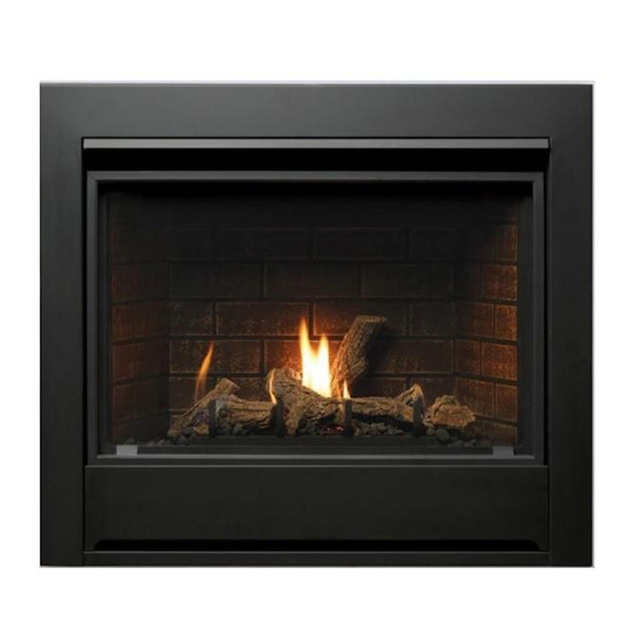
Model Number ZDV3318, ZDV3622, ZDVRB3622
This appliance may be installed in an aftermarket permanently located, manufactured home (USA only) or mobile
home, where not prohibited by local codes.
This appliance is only for use with the type of gas indicated on the rating plate. This appliance is not convertible for
use with other gases, unless a certified kit is used.
These instructions must be kept with the unit for future reference.
WARNING: If the information in these instructions is not followed exactly, a fire or explosion may
result causing property damage, personal injury or loss of life.
Warning: Improper installation, adjustment, alteration, service or maintenance can cause property
damage, personal injury or loss of life. Refer to this manual. Installation and service must be performed by
a qualified installer, service agency or the gas supplier.
Do not store or use gasoline or other flammable vapors and liquids in the vicinity of this or any other appliance.
For Propane Horizontal installations the venting must be a minimum of one foot vertical off the flue before
going horizontal.
A Division of R-Co. Inc.
2340 Logan Avenue
Winnipeg, Manitoba, Canada R2R 2V3
Ph: (204) 632-1962
Printed in Canada April 18, 2013 Part # 3318-MAN-II
Installation Instructions
Zero Clearance Direct Vent Fireplace
Stock #'s: ZDV3318N, ZDV3318NE, ZDV3318LP, ZDV3318LPE
ZDV3622N, ZDV3622NE, ZDV3622LP, ZDV3622LPE
ZDVRB3622N, ZDVRB3622NE, ZDVRB3622LP, ZDVRB3622LPE
Certified to: ANSI Z21.88-2009, CSA 2.33-2009, CGA 2.17-M91
INSTALLER: Leave this manual with the appliance.
CONSUMER: Retain this manual for future reference.
Read this complete manual before beginning installation.
FOR YOUR SAFETY
What To Do If You Smell Gas
Do not try to light any appliance.
Extinguish any open flame.
Do not touch any electrical switch.
Do not use any phone in your building.
Immediately call your gas supplier from a neighbour's phone.
If you can not reach your gas supplier, call the fire department.
Advertisement
Table of Contents


Need help?
Do you have a question about the ZDV3318 and is the answer not in the manual?
Questions and answers