Table of Contents
Advertisement
Quick Links
Kichler
®
Lighting
7711 East Pleasant Valley Road
P.O. Box 318010
Cleveland, Ohio 44131-8010
Customer Service
866.558.5706
8:30 AM to 5:00 PM EST,
Monday - Friday
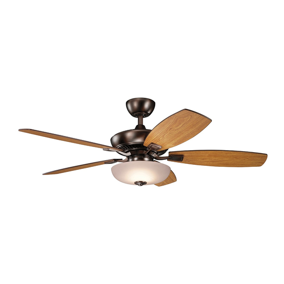
52" Canfield Pro
Includes our Basic Function
CoolTouch
Control System
TM
Looks permanent, but goes wherever you go!
U.S. Patent Pending
Instruction Manual
TM
A Kichler
®
Select
™
ceiling fan
Advertisement
Table of Contents

Related Manuals for Kichler Lighting 52” Canfield Pro


Summary of Contents for Kichler Lighting 52” Canfield Pro
- Page 1 52” Canfield Pro A Kichler ® Select ™ ceiling fan Includes our Basic Function CoolTouch Control System Looks permanent, but goes wherever you go! U.S. Patent Pending Kichler ® Lighting 7711 East Pleasant Valley Road P.O. Box 318010 Cleveland, Ohio 44131-8010...
-
Page 2: Safety Rules
1. SAFETY RULES 1. To reduce the risk of electric shock, insure 8. Avoid placing objects in the path of the electricity has been turned off at the circuit blades. breaker or fuse box before beginning. 9. To avoid personal injury or damage to the 2. -
Page 3: Tools And Materials Required
52” Canfield 2. TOOLS AND MATERIALS REQUIRED Philips screw driver Blade screw driver 11 mm wrench Step ladder Wire cutters 3. PACKAGE CONTENTS Unpack your fan and check the contents. You should have the following items: Fan blades (5) Canopy & Ceiling mounting bracket Ball/downrod assembly Coupling cover Fan motor assembly... -
Page 4: Mounting Options
4. MOUNTING OPTIONS If there isn't an existing UL (cUL for Canadian Installation) listed mounting box, then read the following instructions. Disconnect the power by removing fuses or turning off circuit breakers. Secure the outlet box directly to the building structure. -
Page 5: Hanging The Fan
52” Canfield 5. HANGING THE FAN REMEMBER to turn off the power before you Ceiling mounting bracket begin. To properly install your ceiling fan, follow the Canopy steps below. Step 1. Remove the decorative canopy bottom Canopy cover cover from the canopy by turning the cover Fig. - Page 6 Step 8. Slip the coupling cover, canopy cover and canopy onto the downrod. Cross pin Hanger ball Hanger ball Thread the hanger ball onto the downrod, insert the cross pin through the downrod and Downrod tighten. Now tighten the set screw. (Fig. 9) Canopy Step 9.
-
Page 7: Installation Of Safety Support
52” Canfield 6. INSTALLATION OF SAFETY SUPPORT (required for Canadian installation ONLY) A safety support cable is provided to help prevent the ceiling fan from falling, please install it as follows. Ceiling mounting Attach bracket safety cable Step 1. Attach the provided wood screw and to ceiling joist washers to the ceiling joist next to the mounting with screw and... -
Page 8: Finishing The Installation
Connect the white wire from the fan to the white wire marked "TO MOTOR N" from the Outlet box receiver. Connect the blue wire from the fan to White (neutral) the blue wire marked "FOR LIGHT" from the Black (hot) receiver. -
Page 9: Attaching The Fan Blades
52” Canfield 9. ATTACHING THE FAN BLADES CAUTION: Remove the five rubber shipping blocks attached to the face of the motor. These blocks keep the motor from shifting during shipping and MUST be removed during installation. Step 1. Attach a blade to a blade bracket using the screws and fiber washers provided. -
Page 10: Installing The Light Fixture
11. INSTALLING THE LIGHT FIXTURE Wire connectors Step 1. Remove the plastic plug from the Lock washer center of the switch housing. Attach the light Switch housing Plug fixture to the switch housing by feeding the light fixture wires (black & white) through the hole in the center of the switch housing, then screw the light fixture stem into the center Light fixture... - Page 11 52” Canfield 12. INSTALLING THE LAMPS AND GLASS SHADE Step 1. Install 2, 13 Watt, E27 compact fluorescent lamps (included). (Fig. 20) Step 2. Remove the decorative nut, glass cap and metal nut from the light fixture stem. Place the glass shade over the light fixture stem and secure the shade with a metal nut (rubber side touching the shade).
-
Page 12: Installing The Batteries
13. INSTALLING THE BATTERIES Remove the battery compartment cover on the back of the CoolTouch™ Transmitter and insert both batteries provided. Make sure the + sign is facing up. Take care during this procedure NOT TO move the frequency dip switches inside this compartment. The settings MUST remain the same as the settings on the receiver for proper communication with the control system. - Page 13 52” Canfield 15. OPERATING INSTRUCTIONS The Black Slide Switch on the side of the switch housing controls the direction of the blades "Forward and Reverse". Warm weather - Forward (counter clockwise) A downward airflow creates a cooling effect as shown in Fig. 24. This allows you to set your air conditioner on a warmer setting without affecting your comfort.
-
Page 14: Installing The Cooltouch Control System Wall Plate
™ 16. INSTALLING THE COOLTOUCH Outlet box CONTROL SYSTEM WALL PLATE Switch Select a location to install your CoolTouch™ Control System Transmitter. You can replace Wall plate an existing wall switch, or install the transmitter on ANY flat surface. Option 1: Install the control system using an existing wall switch outlet box. -
Page 15: Troubleshooting
52” Canfield 18. TROUBLESHOOTING Problem Solution Fan will not start. 1. Check circuit fuses or breakers. 2. Check all electrical connections to insure proper contact. CAUTION: Make sure the main power is OFF when checking any electrical connection. 3. Make sure the transmitter batteries are installed properly. Positive (+) side facing out.
Need help?
Do you have a question about the 52” Canfield Pro and is the answer not in the manual?
Questions and answers