Table of Contents
Advertisement
Quick Links
Advertisement
Table of Contents

Related Manuals for Kichler Lighting 330013


Summary of Contents for Kichler Lighting 330013
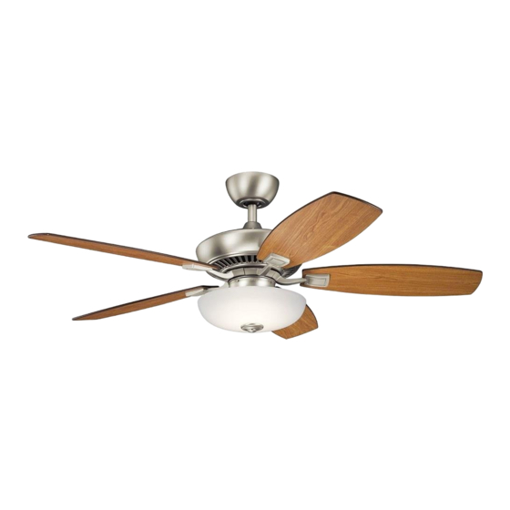
- Page 1 52" Canfield™Pro LED Includes our new Wall Remote Control System Kichler ® Lighting 7711 East Pleasant Valley Road P.O. Box 318010 Cleveland, Ohio 44131-8010 Instruction Manual Customer Service 866.558.5706 8:30 AM to 5:00 PM EST, Monday - Friday...
-
Page 2: Safety Rules
1. SAFETY RULES 9. To avoid personal injury or damage to the 1. To reduce the risk of electric shock, insure electricity has been turned off at the circuit fan and other items, be cautious when breaker or fuse box before beginning. working around or cleaning the fan. -
Page 3: Tools And Materials Required
52" Canfield Pro LED 2. TOOLS AND MATERIALS REQUIRED Philips screw driver Blade screw driver 11 mm wrench Step ladder Wire cutters 3. PACKAGE CONTENTS Unpack your fan and check the contents. You should have the following items: Fan blades (5) Canopy &... -
Page 4: Mounting Options
4. MOUNTING OPTIONS If there isn't an existing UL (cUL for Canadian Installation) listed mounting box, then read the following instructions. Disconnect the power by removing fuses or turning off circuit breakers. Secure the outlet box directly to the building Outlet box structure. -
Page 5: Hanging The Fan
52" Canfield Pro LED 5. HANGING THE FAN Hanger bracket REMEMBER to turn off the power before you begin. Ceiling To properly install your ceiling fan, follow the canopy steps below. Canopy cover Step 1. Remove the decorative canopy Fig. 5 bottom cover from the canopy by turning the cover counter clockwise. - Page 6 Step 8. Slip the coupling cover, canopy cover and canopy onto the downrod. Thread the hanger ball onto the downrod, insert the cross pin through the downrod and Downrod tighten. Now tighten the set screw. (Fig. 9) Canopy Step 9. Lift the motor assembly into position Canopy cover and place the hanger ball into the ceiling mounting bracket.
-
Page 7: Installation Of Safety Support
52" Canfield Pro LED 6. INSTALLATION OF SAFETY SUPPORT (required for Canadian installation ONLY) A safety support cable is provided to help prevent the ceiling fan from falling, please install Hanger bracket it as follows. Safety cable Step 1. Attach the provided wood screw and Attach safety cable to ceiling joist with washers to the ceiling joist next to the mounting... -
Page 8: Finishing The Installation
Connect the white wire from the fan to the white Outlet box wire marked "TO MOTOR N" on the receiver. Connect the blue wire from the fan to the blue White (neutral) wire marked "FOR LIGHT" on the receiver. Black (hot) Secure all the wire connections with the plastic Green or bare copper (ground) -
Page 9: Attaching The Fan Blades
52" Canfield Pro LED 9. ATTACHING THE FAN BLADES CAUTION: Remove the rubber shipping plate attached to the face of the motor. These plate keep the motor from shifting during shipping and MUST be removed during installation. Step 1. Attach a blade to a blade bracket using the screws and fiber washers provided. - Page 10 11. INSTALLING THE LIGHT KIT TO SWITCH HOUSING Remove and discard the center plug from the Lock washer switch housing. Attach the light kit to the switch housing by feeding the light kit wires (black and white) through the hole in the center of the switch housing and then screw the threaded pipe on the light kit into the Switch housing...
-
Page 11: Installing The Glass Shade
52" Canfield Pro LED 13. INSTALLING THE GLASS SHADE Step 1. Remove the decorative nut, glass cap and metal nut from the LED light kit. Place glass shade over the LED light kit stem, secure with the metal nut (rubber side on the top), add the glass cap and decorative nut. -
Page 12: Installing The Batteries
14. INSTALLING THE BATTERIES Remove the face plate of the Wall Switch by lifting at the top and then insert the supplied 12V battery. Duracell MN21/Eveready A23/GP LIGHT 23A all 12V. ON ECE Replace the switch face plate. FAN OFF 1 2 3 4 To prevent possible damage to the transmitter, remove these batteries if not used... - Page 13 52" Canfield Pro LED 16. INSTALLING THE BASIC FUNCTION WALL CONTROL SYSTEM WALL Outlet box PLATE Switch Wall plate Select a location to install the Basic Function Wall Control System Transmitter and Wall Plate. Install the wall plate using an existing wall switch outlet box.
- Page 14 17. OPERATING INSTRUCTIONS The Black Slide Switch on the side of the switch housing controls the direction of the blades "Forward and Reverse". Warm weather - Forward (counter clockwise) A downward airflow creates a cooling effect as shown in Fig. 26. This allows you to set your air conditioner on a warmer setting without affecting your comfort.
-
Page 15: Troubleshooting
52" Canfield Pro LED 18. TROUBLESHOOTING Problem Solution Fan will not start. 1. Check circuit fuses or breakers. 2. Check all electrical connections to insure proper contact. CAUTION: Make sure the main power is OFF when checking any electrical connection. 3.
Need help?
Do you have a question about the 330013 and is the answer not in the manual?
Questions and answers