
Related Manuals for ADLINK Technology PCIe-FIW Series


Summary of Contents for ADLINK Technology PCIe-FIW Series
- Page 1 PCIe-FIW Series 1394b PCI Express Frame Grabber User’s Manual Manual Rev. 2.01 Revision Date: November 22, 2008 Part No: 50-11159-1000 Advance Technologies; Automate the World.
- Page 2 Copyright 2008 ADLINK TECHNOLOGY INC. All Rights Reserved. The information in this document is subject to change without prior notice in order to improve reliability, design, and function and does not represent a commitment on the part of the manufacturer.
- Page 3 Getting Service from ADLINK Customer Satisfaction is top priority for ADLINK Technology Inc. Please contact us should you require any service or assistance. ADLINK TECHNOLOGY INC. Web Site: http://www.adlinktech.com Sales & Service: Service@adlinktech.com TEL: +886-2-82265877 FAX: +886-2-82265717 Address: 9F, No. 166, Jian Yi Road, Chungho City,...
-
Page 5: Table Of Contents
Table of Contents Table of Contents..............i List of Tables................iii List of Figures ................ iv 1 Introduction ................ 1 Features................2 Applications ................. 2 2 Hardware Reference............3 PCIe-FIW64 Specifications..........3 PCIe-FIW64 Outline ............4 PCIe-FIW64 Connectors and Pin Definitions ....5 PCIe-FIW62 Specifications.......... - Page 6 FIW64_GetErrorMessage ..........43 Error Codes................ 44 Table of Contents...
-
Page 7: List Of Tables
List of Tables Table 2-1: 1394b Pinout ............5 Table 2-2: Additional 12 V Power Input Port ......6 Table 2-3: IEEE1394 Connection Status LEDs ......6 Table 2-4: Card ID Select ............7 Table 2-5: Card ID Select Table ..........7 Table 2-6: GPIO &... -
Page 8: List Of Figures
List of Figures Figure 2-1: PCIe-FIW64 Outline ..........4 Figure 2-2: PCIe-FIW62 Diagram ..........15 List of Figures... - Page 9 List of Figures...
-
Page 10: Introduction
1394b cameras. The IEEE 1394b standard also supports a power over cable feature to reduce wiring. The 4-pin ATX power connector on the PCIe-FIW series allows the 1394 cameras that are connected to draw power. The LEDs on the front panel of the PCIe-FIW series will illuminate when a PCIe-FIW card is connected to a 1394b camera, thus making it is easy to identify the channel connection status. -
Page 11: Features
1.1 Features PCI Express compliant PCIe-FIW62: x1 PCI Express PCIe-FIW64: x4 PCI Express High-speed image transfer rates up to 800 Mb/s Provides industrial screw lock connector Status LED for channel activation Four isolated digital inputs/outputs ... -
Page 12: Hardware Reference
Hardware Reference 2.1 PCIe-FIW64 Specifications IEEE1394b Port Four IEEE1394b fully compliant cable ports at 100 Mbits/s, 200 Mbits/s, 400 Mbits/s, and 800 Mbits/s. Fully supports provisions of IEEE P1394b-2002. Fully compliant with provisions of IEEE std 1394-1995 for a high performance serial bus and IEEE std 1394a- 2000. -
Page 13: Pcie-Fiw64 Outline
PCIe-FIW64 Power Requirements +12 V max, 200 mA +3.3 V max, 2.5 A 2.1.1 PCIe-FIW64 Outline Figure 2-1: PCIe-FIW64 Outline Hardware Reference... -
Page 14: Pcie-Fiw64 Connectors And Pin Definitions
2.1.2 PCIe-FIW64 Connectors and Pin Definitions CN1-CN4: IEEE1394b Port Pin Signal Pin Signal TPB- TPB+ TPA- TPA+ TPB(R) TPA(R) Table 2-1: 1394b Pinout Hardware Reference... -
Page 15: Table 2-2: Additional 12 V Power Input Port
CN5: Additional 12 V Power Input Port Signal +12 V Table 2-2: Additional 12 V Power Input Port LED19-LED22: IEEE1394 Connection Status LEDs Component Function Description CN1 IEEE1394 bus connection Green light: Normal LED19 status display. connection CN2 IEEE1394 bus connection Green light: Normal LED20 status display. -
Page 16: Table 2-4: Card Id Select
SW1: Card ID Select Card ID: up to four cards supported Signal Name Default Board ID Select 0 Board ID Select 1 Non use Non use Table 2-4: Card ID Select Card ID Board ID Select 0 Board ID Select 1 Table 2-5: Card ID Select Table Hardware Reference... -
Page 17: Table 2-6: Gpio & Trigger
CN5: GPIO & Trigger Pin Name Type Pin Pin Name Type System Power(+12V) OUT System GND Digital input 1 Digital input common 1 Digital input 2 Digital input common 2 Digital input 3 Digital input common 3 Digital input 4 Digital input common 4 Digital output 1 OUT 12 Digital output common 1 OUT... - Page 18 Digital Input Circuit Digital Output Circuit Trigger Input Circuit Trigger Output Circuit Hardware Reference...
-
Page 19: Table 2-7: Specifications
Function Electronic Specification Isolated Digital Input Photo Coupled Input x 4 ch Input voltage range 0 to 25 V Low level 0 to 0.5 V High Level 2 to 25 V Isolated Digital Output Photo Coupled Output x 4 ch Load voltage range 3 to 24 V Output sink current... -
Page 20: Table 2-8: Trigger Control Timing
Trigger Control Timing Chart Symbol Characteristic Specification Trigger input pulse width 0.1 msec (min.) 0 to 1000 msec selectable (1 msec step) Trigger delay Actual delay = Selected delay time Output trigger pulse width 0.1 to 50 msec selectable (0.1 msec step) Table 2-8: Trigger Control Timing Trigger Busy Control Symbol... - Page 21 Trigger Enable Control Hardware Reference...
-
Page 22: Table 2-9: Extension Cable Connector
Extension Cable Connector The extension cable connector is a D-sub 37 pin female connec- tor. Pin Name Type Pin Pin Name Type System Power(+12V) OUT 20 System GND Digital input 1 Digital input common 1 Digital input 2 Digital input common 2 Digital input 3 Digital input common 3 Digital input 4... -
Page 23: Pcie-Fiw62 Specifications
2.2 PCIe-FIW62 Specifications External device signal input Channel ports (1 and 2) : 1394b 9-pin connector with screw 1394b differential signals Form factor PCI-express x1 interface User EEPROM Includes 2 kbit available EEPROM Dimension W x L: 78.6 mm x 105.7 5mm Power Requirements ... -
Page 24: Pcie-Fiw62 Appearance
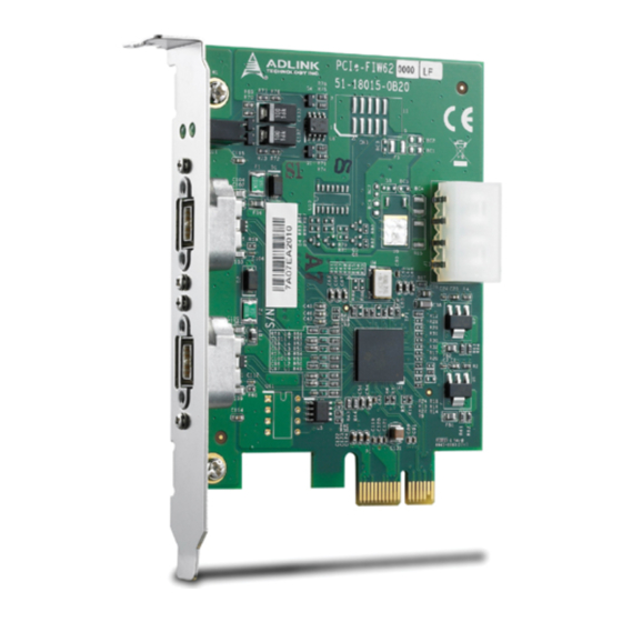
2.2.1 PCIe-FIW62 Appearance Figure 2-2: PCIe-FIW62 Diagram Hardware Reference... -
Page 25: Pcie-Fiw62 Connectors And Pin Definitions
2.2.2 PCIe-FIW62 Connectors and Pin Definitions Pin Number Pin Definition Function TPB- Twisted Pair B, Minus TPB+ Twisted Pair B, Plus TPA- Twisted Pair A, Minus TPA+ Twisted Pair A, Plus TPA (R) Ground, Twisted Pair A Power Ground No Connection Power Voltage TPB (R) Ground, Twisted Pair B... -
Page 26: Table 2-12: Disk Power Pinout
Pin Number Pin Definition Function +5 Voltage Ground Ground +12V +12 Voltage Table 2-12: Disk Power Pinout Hardware Reference... - Page 27 Hardware Reference...
-
Page 28: Installation Guide
Installation Guide 3.1 Hardware Installation Use the following steps to install the PCIe-FIW series card on the PCI Express bus: 1. Remove the computer cover using the instructions from the computer manual. 2. Check that there is an empty PCI express slot accom- modated the board. -
Page 29: Driver Installation
3.2 Driver Installation 1. Microsoft Windows will automatically install 1394 driver through a built-in OHCI IEEE-1394 driver. 2. Go to the Device Manager and check IEEE 1394 Bus host controllers, you should see the following item: Texas Instruments OHCI Compliant IEEE 1394 Host Controller Installation Guide... - Page 30 2.1. If there is a yellow exclamation mark in front of the new driver name, you will need to setup the driver manually. 2.2. Right-click IEEE 1394 Controller and select Update driver. Installation Guide...
- Page 31 2.3. Click Next 2.4. Click Next Installation Guide...
- Page 32 2.5. Click Next Installation Guide...
- Page 33 2.6. Click Finish to complete the wizard. 3. For the PCIe-FIW64, after installing the IEEE-1394 driver, please double-click FIW64_SetupDisk.exe to start driver installation of the ADLINK FIW64 DI/O and trigger function. Installation Guide...
- Page 34 4. Click Next to continue driver installation. 5. Click Install to begin the installation. Installation Guide...
- Page 35 6. Click Finish to complete driver installation. Installation Guide...
- Page 36 Note: If using Windows Vista, there is an important setting must be performed in order for the PCIe-FIW series to function prop- erly. Perform the following to turn off the User Account Con- trol (UAC). 1. Click Start -> Settings -> Control Panel -> User Accounts ->...
- Page 37 Installation Guide...
-
Page 38: Function Library
Function Library 4.1 Function List Function Name Description System Functions Loads the FIW64 driver. This function must be FIW64_Initialize called before any other functions. Obtain the number of the FIW64 cards in the FIW64_GetTotalDeviceNum system. Obtain the CardIDs of the FIW64 cards in the FIW64_GetTotalDeviceID system. -
Page 39: Functions
4.2 Functions 4.2.1 FIW64_Initialize Description Loads the FIW64 driver. This function must be called before any other functions. Syntax int FIW64_Initialize(); Function Library... -
Page 40: Fiw64_Gettotaldevicenum
4.2.2 FIW64_GetTotalDeviceNum Description Obtain the number of the FIW64 cards in the system. Syntax int FIW64_GetTotalDeviceNum(int *DeviceNum); Parameters DeviceNum [out] Pointer to a 32-bit integer which stores the read out Card Number. Function Library... -
Page 41: Fiw64_Gettotaldeviceid
4.2.3 FIW64_GetTotalDeviceID Description Obtain the CardIDs of the FIW64 cards in the system. Syntax int FIW64_GetTotalDeviceID(int *DeviceID, int ArrayLen ); Parameters DeviceID [out] Pointer to a 32-bit integer array which stores the read out CardID(s) defined by the DIP switch on FIW64. ArrayLen [in] Length of the 32-bit integer array of DeviceID. -
Page 42: Fiw64_Resetdevice
4.2.4 FIW64_ResetDevice Description Resets the FIW64 card to the default status. Syntax int FIW64_ResetDevice(int ChannelNo); Parameters ChannelNo [in] Channel No. of the FIW64 card. The channel No. can be 0, 1, 2 and 3 in the device whose Card ID is 0; moreover, it can be 4, 5, 6 and 7 in the device whose Card ID is 1, etc. -
Page 43: Fiw64_Getfirmwareversion
4.2.5 FIW64_GetFirmwareVersion Description Obtain the firmware version of the FIW64 card. Syntax int FIW64_GetFirmwareVersion(int ChannelNo, int *Version); Parameters ChannelNo [in] Channel No. of the FIW64 card. The channel No. can be 0, 1, 2 and 3 in the device whose Card ID is 0; moreover, it can be 4, 5, 6 and 7 in the device whose Card ID is 1, etc. -
Page 44: Fiw64_Setdo
4.2.6 FIW64_SetDO Description Set the general purpose digital output status. Syntax int FIW64_SetDO(int ChannelNo,int Status); Parameters ChannelNo [in] Channel No. of the FIW64 card. The channel No. can be 0, 1, 2 and 3 in the device whose Card ID is 0; moreover, it can be 4, 5, 6 and 7 in the device whose Card ID is 1, etc. -
Page 45: Fiw64_Getdi
4.2.7 FIW64_GetDI Description Obtain the general purpose digital input status. Syntax int FIW64_GetDI(int ChannelNo,int *Status); Parameters ChannelNo [in] Channel No. of the FIW64 card. The channel No. can be 0, 1, 2 and 3 in the device whose Card ID is 0; moreover, it can be 4, 5, 6 and 7 in the device whose Card ID is 1, etc. -
Page 46: Fiw64_Gettriggerdelaytime
4.2.8 FIW64_GetTriggerDelayTime Description Obtain the delay time of the output triggers. Syntax int FIW64_GetTriggerDelayTime(int ChannelNo,int *DelayTime); Parameters ChannelNo [in] Channel No. of the FIW64 card. The channel No. can be 0, 1, 2 and 3 in the device whose Card ID is 0; moreover, it can be 4, 5, 6 and 7 in the device whose Card ID is 1, etc. -
Page 47: Fiw64_Settriggerdelaytime
4.2.9 FIW64_SetTriggerDelayTime Description Set the delay time of the output triggers. Syntax int FIW64_SetTriggerDelayTime(int ChannelNo,int DelayTime); Parameters ChannelNo [in] Channel No. of the FIW64 card. The channel No. can be 0, 1, 2 and 3 in the device whose Card ID is 0; moreover, it can be 4, 5, 6 and 7 in the device whose Card ID is 1, etc. -
Page 48: Fiw64_Gettriggerwidth
4.2.10 FIW64_GetTriggerWidth Description Obtain the width of the output triggers. Syntax int FIW64_GetTriggerWidth(int ChannelNo,int * Width); Parameters ChannelNo [in] Channel No. of the FIW64 card. The channel No. can be 0, 1, 2 and 3 in the device whose Card ID is 0; moreover, it can be 4, 5, 6 and 7 in the device whose Card ID is 1, etc. -
Page 49: Fiw64_Settriggerwidth
4.2.11 FIW64_SetTriggerWidth Description Set the width of the output triggers. Syntax int FIW64_SetTriggerWidth(int ChannelNo,int Width); Parameters ChannelNo [in] Channel No. of the FIW64 card. The channel No. ccan be 0, 1, 2 and 3 in the device whose Card ID is 0; moreover, it can be 4, 5, 6 and 7 in the device whose Card ID is 1, etc. -
Page 50: Fiw64_Gettriggerpolarity
4.2.12 FIW64_GetTriggerPolarity Description Obtain the polarity of the input and output triggers. Syntax int FIW64_GetTriggerPolarity(int ChannelNo,int *Status); Parameters ChannelNo [in] Channel No. of the FIW64 card. The channel No. can be 0, 1, 2 and 3 in the device whose Card ID is 0; moreover, it can be 4, 5, 6 and 7 in the device whose Card ID is 1, etc. -
Page 51: Fiw64_Settriggerpolarity
4.2.13 FIW64_SetTriggerPolarity Description Set the input and output polarity of the output triggers. Syntax int FIW64_SetTriggerPolarity(int ChannelNo,int Status); Parameters ChannelNo [in] Channel No. of the FIW64 card. The channel No. can be 0, 1, 2 and 3 in the device whose Card ID is 0; moreover, it can be 4, 5, 6 and 7 in the device whose Card ID is 1, etc. - Page 52 4.2.14 FIW64_GetErrorMessage Description Obtain the Error Message by returning the value of functions. Syntax int FIW64_GetErrorMessage(int ErrorCode, char* ErrorMessage); Parameters ErrorCode [in] A 32-bit integer variable which specifies the error code. ErrorMessage [out] Pointer to a character array which stores the read out error message.
-
Page 53: Error Codes
4.3 Error Codes Error Code Meaning ERROR_NoError ERROR_DeviceNotExist ERROR_LoadDriverFail ERROR_DeviceCannotOpen ERROR_DeviceCannotAccess ERROR_Invalid_ChannelNo ERROR_SPIFunctionError ERROR_ParameterExceedLimit ERROR_CardIDError Function Library...
Need help?
Do you have a question about the PCIe-FIW Series and is the answer not in the manual?
Questions and answers