
Related Manuals for ADLINK Technology PCIe-8560


Summary of Contents for ADLINK Technology PCIe-8560
- Page 1 PCIe-8560 PXI-8565 ® PCI Express -to-PXI™ Extension Kit User’s Manual Manual Revision: 2.00 Revision Date: October 24, 2007 Part Number: 50-17027-1000 Advance Technologies; Automate the World.
-
Page 2: Pcie-8560 Pxi-8565
PCIe-8560 PXI-8565 User’s Manual Revision History Revision Release Date Description of Change(s) 2.00 2007/10/24 Initial Release... -
Page 3: Preface
PCIe-8560 PXI-8565 User’s Manual Preface Copyright 2007 ADLINK TECHNOLOGY INC. This document contains proprietary information protected by copy- right. All rights are reserved. No part of this manual may be repro- duced by any mechanical, electronic, or other means in any form without prior written permission of the manufacturer. -
Page 4: Using This Manual
PCIe-8560 PXI-8565 User’s Manual Using this Manual Audience and Scope The PCIe-8560 PXI-8565 User’s Manual is intended for hardware technicians and systems operators with knowledge of installing, ® configuring and using PCI Express -to-PXI™ extension systems. This document is specifically intended to describe connecting ®... -
Page 5: Conventions
PCIe-8560 PXI-8565 User’s Manual Conventions Take note of the following conventions used throughout this manual to make sure that users perform certain tasks and instructions properly. Additional information, aids, and tips that help users per- form tasks. NOTE: NOTE: Information to prevent minor physical injury, component damage, data loss, and/or program corruption when try- ing to complete a task. -
Page 6: Reference Documentation
PCIe-8560 PXI-8565 User’s Manual Reference Documentation The following list of documents may be used as reference materi- als to support installation, configuration and/or the operation of the PCI Express-to-PXI Extension Kit. This list is prepared in alpha- betical order (by vendor name, then by document title) for clarity. -
Page 7: Getting Service
Sales & Service: info@adlinktech.com Toll-Free: +1-866-423-5465 Fax No.: +1-949-727-2099 Mailing Address: 8900 Research Drive, Irvine, CA 92618, USA ADLINK TECHNOLOGY CO. LTD. (BEIJING) Sales & Service: market@adlinkchina.com.cn Telephone No.: +86-10-5885-8666 Fax No.: +86-10-5885-8625 Mailing Address: Rm. 801, Power Creative E, No. - Page 8 Sales & Service japan@adlinktech.com Telephone No. +81-3-4455-3722 Fax No. +81-3-5333-6040 Mailing Address Asahiseimei Hatagaya Bld. 1-1-2 Hatagaya Shibuya-ku, Tokyo, Japan ADLINK TECHNOLOGY INC. (SOUTH KOREA) Sales & Service: korea@adlinkchina.com.cn Telephone No.: +82-2-2057-0565 Fax No.: +82-2-2057-0563 Mailing Address: 4F, Kostech Building, 262-2,...
-
Page 9: Table Of Contents
Applications ................. 5 2 Getting Started ..............7 Installation Environment ............7 Installing PCIe-8560 on a Host Computer ......8 Installing PXI-8565 to a PXI™ Chassis ......10 Cabling Host Computer to PXI™ Extension Chassis ..11 Power-ON/OFF Sequence..........14 LED Status................. -
Page 10: Table Of Contents
PCIe-8560 PXI-8565 User’s Manual 3.2.1 PCIe-8560 S1/S2 Signal Equalizer Adjustments ....19 PXI-8565 Layout, Connectors and Jumpers ...... 21 Extension Cable Options ........... 23 4 Troubleshooting (FAQ)............. 25 Important Safety Instructions..........29 Warranty Policy ..............31 Table of Contents... -
Page 11: List Of Figures
PCIe-8560 PXI-8565 User’s Manual List of Figures Figure 2-1: PCIe-8560 to Host PC Installation Diagram ....9 Figure 2-2: PXI-8565 to PXI™ Chassis Installation Diagram... 10 Figure 2-3: 3 M extension cable (ACL-EXPRESS-3) ....... 11 Figure 2-4: Cabling 3 M Extension Cable to Host PC ...... 12 Figure 2-5: Cabling 3 M Extension Cable to PXI™... - Page 12 PCIe-8560 PXI-8565 User’s Manual This page intentionally left blank. List of Figures...
-
Page 13: List Of Tables
Table 2-1: PCIe-8560 to Host PC Chassis Installation Items ... 9 Table 3-1: PCIe-8560 Connectors, Jumpers and LED ....18 Table 3-2: PCIe-8560 Pin 1 and Pin 2 Equalizer Selection .... 19 Table 3-3: PCIe-8560 Pin 3 Output Swing Control ......20 Table 3-4: PCIe-8560 Pin 4 Output De-Emphasis Control ..... - Page 14 PCIe-8560 PXI-8565 User’s Manual This page intentionally left blank. List of Tables...
-
Page 15: Introduction
PCIe-8560 PXI-8565 User’s Manual Introduction This chapter introduces the PCI Express-to-PXI Extension Kit, presents a general overview and basic applications, its package contents, specifications, and features. 1.1 Overview ® Harnessing the bandwidth potential of PCI Express , the PCI Express-to-PXI Extension Kit enables computers with a PCI ®... - Page 16 The PCI Express-to-PXI Extension Kit implements a PCI Express- based control of PXI™ modules. The technology consists of a PCIe-8560 card installed in a host computer, a shielded cable, and a PXI-8565 card installed in the remote PXI™ chassis. The PCIe- ®...
-
Page 17: Package Contents
PCIe-8560 PXI-8565 User’s Manual 1.2 Package Contents PCI Express-to-PXI Extension Kit ® PCIe-8560 (PCI Express extension host card) ® PXI-8565 (PCI Express controller for PXI™ interface) ACL-EXPRESS-3 (3 M extension cable) User's Manual If any of the items on the contents list are missing or damaged, contact your ADLINK dealer. -
Page 18: Specifications
PCIe-8560 PXI-8565 User’s Manual 1.3 Specifications PCIe-8560 (on host computer) ® Compliant with PCI Express Base Specifications Rev. 1.0a ® PCI Express x1 link which provides an effective signaling rate of up to 2.5 Gigabits/sec. Maximum extended distance of up to seven meters Low-profile footprint, 68.90 mm (H) x 86.65 mm (W) -
Page 19: Features
PCIe-8560 PXI-8565 User’s Manual 1.4 Features ® PCI Express control of PXI™ cards ® High-speed PCI Express X1 interface Compatible with 5 V and 3.3 V PCI bus Supports 32-bit/33 MHz PCI interface Extension lengths of 1 M, 3 M and 7 M Complete hardware and software transparency ®... - Page 20 PCIe-8560 PXI-8565 User’s Manual This page intentionally left blank. Introduction...
-
Page 21: Getting Started
PCIe-8560 PXI-8565 User’s Manual Getting Started This chapter describes the installation environment, installation procedures, cabling the equipment, and instructions on powering- on/off the PCI Express-to-PXI Extension Kit. Diagrams and images of equipment mentioned are used for reference only. Actual system appearance may vary. -
Page 22: Installing Pcie-8560 On A Host Computer
® 4. Install the PCIe-8560 in an available X1 PCI Express slot in your host computer. Be sure to firmly attach the PCIe-8560’s bracket to the backplane of the host PC. -
Page 23: Figure 2-1: Pcie-8560 To Host Pc Installation Diagram
PCIe-8560 to Host PC Installation Diagram Item Description ® Industrial PC or Desktop PC with X1 PCI Express Slot PCIe-8560 (PCI Express-to-PCI extension host card) ® X1 PCI Express Slot Table 2-1: PCIe-8560 to Host PC Chassis Installation Items Getting Started... -
Page 24: Installing Pxi-8565 To A Pxi™ Chassis
PCIe-8560 PXI-8565 User’s Manual 2.3 Installing PXI-8565 to a PXI™ Chassis 1. Locate your PXI™ chassis (for illustration purposes, we use the ADLINK PXIS-2508) and plug-in the AC power cord but DO NOT power-on the equipment. 2. Remove the cover panel of the PXI™ chassis system slot. -
Page 25: Cabling Host Computer To Pxi™ Extension Chassis
User’s Manual Cabling Host Computer to PXI™ Extension Chassis Now that you have successfully installed the PCIe-8560 into the Host computer and/or installed a PXI™ device in the PXI™ exten- sion chassis, you may connect the Host Computer and PXI™... -
Page 26: Figure 2-4: Cabling 3 M Extension Cable To Host Pc
PCIe-8560 PXI-8565 User’s Manual Figure 2-4: Cabling 3 M Extension Cable to Host PC Getting Started... -
Page 27: Figure 2-5: Cabling 3 M Extension Cable To Pxi™ Extension Chassis
PCIe-8560 PXI-8565 User’s Manual 4. Connect the other end of the 3 M extension cable to the PXI-8565 serial link connector of the PXI™ extension chassis (PXIS-2508). Figure 2-5: Cabling 3 M Extension Cable to PXI™ Extension Chassis Figure 2-6: Host PC connected to a PXI™ Extension Chassis... -
Page 28: Power-On/Off Sequence
PCIe-8560 PXI-8565 User’s Manual 2.5 Power-ON/OFF Sequence To power-on the PCI Express-to-PXI Extension Kit, follow these steps: 1. Check that the 3 M extension cable is properly con- nected to the host PC and extension chassis. 2. Power-on the PXI™ extension chassis first. -
Page 29: Led Status
PCIe-8560 PXI-8565 User’s Manual 2.6 LED Status The LEDs on the front panel of the PCIe-8560 and PXI-8565 give power status information. The LEDs light up only when the follow- ing conditions are met: The extension cable between the PCIe-8560 (Host PC) and PXI-8565 (Extension Chassis) is properly connected. - Page 30 PCIe-8560 PXI-8565 User’s Manual This page intentionally left blank. Getting Started...
-
Page 31: Hardware Information
PCIe-8560 PXI-8565 User’s Manual Hardware Information 3.1 Functional Block Diagram Figure 3-1: PCI Express-to-PXI Extension Kit Functional Block Diagram Hardware Information... -
Page 32: Pcie-8560 Layout, Connectors And Jumpers
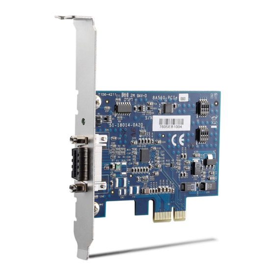
User’s Manual 3.2 PCIe-8560 Layout, Connectors and Jumpers Figure 3-2: PCIe-8560 Mechanical Layout Connector/Jumper/LED Description Adjusts Signal Equalizer Adjusts Signal Equalizer ® PCI Express Serial Link Connector Serial Link Status LED Table 3-1: PCIe-8560 Connectors, Jumpers and LED Hardware Information... -
Page 33: Pcie-8560 S1/S2 Signal Equalizer Adjustments
S2 simultaneously. The S1 transmits signals and S2 is receives signals. NOTE: NOTE: Configuration Description Strongest equalizer levels (default) Moderate equalizer level Weakest equalizer level No equalizer Table 3-2: PCIe-8560 Pin 1 and Pin 2 Equalizer Selection Hardware Information... -
Page 34: Table 3-3: Pcie-8560 Pin 3 Output Swing Control
User’s Manual Configuration Description High level output signal swing (Default) Normal level output signal swing Table 3-3: PCIe-8560 Pin 3 Output Swing Control Configuration Description High level output signal swing (Default) Normal level output signal swing Table 3-4: PCIe-8560 Pin 4 Output De-Emphasis Control... -
Page 35: Pxi-8565 Layout, Connectors And Jumpers
PCIe-8560 PXI-8565 User’s Manual 3.3 PXI-8565 Layout, Connectors and Jumpers Figure 3-3: PCI-8565 Mechanical Layout Connector/Jumper/LED Description Spread spectrum clock control ® PCI Express serial link connector Serial Link Status LED Table 3-5: PXI-8565 Connectors, Jumpers and LED Hardware Information... -
Page 36: Table 3-6: Pxi-8565 J1 Spread Spectrum Clock Control
PCIe-8560 PXI-8565 User’s Manual Setting Description Enables spread spectrum control. When enabling spread spectrum control, the PCI clock will be modulated with a low frequency carrier, the peak EMI can be greatly reduced in the system (Default). Disables spread spectrum control. -
Page 37: Extension Cable Options
PCIe-8560 PXI-8565 User’s Manual 3.4 Extension Cable Options ® The PCI Express -to-PCI extension system (PCES-8581-13S and PCES-8581-4S) is available with three different cables in length. These cables are designed to transfer high speed signals and have high immunity from electromagnetic interference. - Page 38 PCIe-8560 PXI-8565 User’s Manual This page intentionally left blank. Hardware Information...
-
Page 39: Troubleshooting (Faq)
This Troubleshooting (FAQ) applies to: PCI Express-to-PCI Extension System: including PCES- 8581-4S and PCES-8581-13S. PCI Express-to-PXI Extension Kit: including PCIe-8560 and PXI-8565. In the following description, the products will be renamed as "PCI ®... - Page 40 PCIe-8560 PXI-8565 User’s Manual be supported by one chassis. However, users can select multiple extension chassis for different purposes. For exam- ple, a 4-slot extension chassis provides small and compact form factor while an 18-slot extension chassis provides more PCI slots. Theoretically, PCI specification allows up to ®...
- Page 41 PCIe-8560 PXI-8565 User’s Manual The following list are some indications that may help customers to deal with compatibility issues: 1. Disable the onboard device functions of your host PC to release IO resources. 2. Remove PCI devices plugged/installed in your host PC.
- Page 42 PCIe-8560 PXI-8565 User’s Manual This page intentionally left blank. Troubleshooting (FAQ)
-
Page 43: Important Safety Instructions
PCIe-8560 PXI-8565 User’s Manual Important Safety Instructions For user safety, please read and follow all instructions, WARNINGS, CAUTIONS, and NOTES marked in this manual and on the associated equipment before handling/operating the equipment. Read these safety instructions carefully. Keep this user’s manual for future reference. - Page 44 PCIe-8560 PXI-8565 User’s Manual Never attempt to fix the equipment. Equipment should only be serviced by qualified personnel. A Lithium-type battery may be provided for uninterrupted, backup or emergency power. RISK OF EXPLOSION IF BATTERY IS REPLACED BY AN INCORECT TYPE. DISPOSE OF USED BATTERIES ACCORDING TO THEIR INSTRUCTIONS.
-
Page 45: Warranty Policy
PCIe-8560 PXI-8565 User’s Manual Warranty Policy Thank you for choosing ADLINK. To understand your rights and enjoy all the after-sales services we offer, please read the follow- ing carefully. 1. Before using ADLINK’s products please read the user manual and follow the instructions exactly. When send-... - Page 46 PCIe-8560 PXI-8565 User’s Manual 3. Repair service is not covered by ADLINK's two-year guarantee in the following situations: Damage caused by not following instructions in the User's Manual. Damage caused by carelessness on the user's part during product transportation. Damage caused by fire, earthquakes, floods, lightening, pollution, other acts of God, and/or incorrect usage of volt- age transformers.
Need help?
Do you have a question about the PCIe-8560 and is the answer not in the manual?
Questions and answers