
Related Manuals for ADLINK Technology PCIe-2602


Summary of Contents for ADLINK Technology PCIe-2602
- Page 1 PCIe-2602 3G-SDI Audio/Video Capture Card User’s Manual 3.00 Manual Rev.: Aug. 23, 2013 Revision Date: 50-11251-1010 Part No: Advance Technologies; Automate the World.
-
Page 2: Revision History
Revision History Revision Release Date Description of Change(s) 2.00 June 28, 2013 Initial release 3.00 Aug. 23, 2013 Revised specification... -
Page 3: Preface
PCIe-2602 Preface Copyright 2013 ADLINK Technology, Inc. This document contains proprietary information protected by copy- right. All rights are reserved. No part of this manual may be repro- duced by any mechanical, electronic, or other means in any form without prior written permission of the manufacturer. - Page 4 Conventions Take note of the following conventions used throughout this manual to make sure that users perform certain tasks and instructions properly. Additional information, aids, and tips that help users perform tasks. NOTE: NOTE: Information to prevent minor physical injury, component dam- age, data loss, and/or program corruption when trying to com- plete a task.
-
Page 5: Table Of Contents
PCIe-2602 Table of Contents Revision History..............ii Preface ..................iii List of Figures ............... vii List of Tables................ix 1 Introduction ................ 1 Overview................1 Features................1 Applications ................. 1 Specifications............... 2 1.4.1 Software Support............2 1.4.2 Video & Audio............. 2 1.4.3... - Page 6 Audio Format Menu ..........38 A.0.8 Image Size Menu............39 A.0.9 Tool Menu..............39 A.0.10 Help Menu ..............40 B Appendix: PCIe-2602 Benchmark........43 Recommended System Configuration ....... 43 Benchmarks ............... 43 B.2.1 Test 1................ 43 B.2.2 Test 2................ 44 B.2.3 Test 3................
-
Page 7: List Of Figures
Figure 1-9: LED Indicators ............... 13 Figure 1-10: Switch Locations............15 Figure 1-11: PCIe-2602 Digital Input Functional Block Diagram..17 Figure 1-12: Sinking DI: Slider # of Switch 4 OFF ......18 Figure 1-13: Sourcing DI: Slider # of Switch 4 is ON ......19 Figure 1-14: PCIe -2602 Digital Output Functional Block Diagram.. - Page 8 This page intentionally left blank. viii List of Figures...
-
Page 9: List Of Tables
PCIe-2602 List of Tables Table 1-1: Board Layout Legend ............7 Table 1-2: SDI Connector Pin Assignment ........8 Table 1-3: RS-485 Connector Pin Assignment ......... 9 Table 1-4: D I/O Connector Pin Assignments ......... 10 Table 1-5: D-sub Connector Cable Exterior Connector Pin Assignments ............ - Page 10 This page intentionally left blank. List of Tables...
-
Page 11: Introduction
Directshow support RS-485 and Digital I/O provided PCI Express x4 compliant signal Connection Status LED 1.3 Applications The PCIe-2602, featuring 3G signal capture ability and support for highly accurate color formatting, is ideal for frame grab function in Introduction... -
Page 12: Specifications
NOTE: NOTE: 1.4 Specifications The PCIe-2602 provides 2 BNC connectors that support 2 chan- nels of video and embedded audio, with maximum video data throughput of 2.97Gb/s, with 1.485G and 270M bps supported, and RS-485 and digital I/O simplify connection with other devices. - Page 13 PCIe-2602 Item Specification 525i(720x486i@59.94/60Hz), SD Interlace pattern 625i(720x576i@50Hz) 1080i50(1920x1080i@50Hz), HD interlace pattern 1080i60(1920x1080i@59.94/60Hz) 720p24(1280x720p@24Hz), 720p25(1280x720p@25Hz), Video input 720p30(1280x720p@30Hz), resolution 720p50(128x720p@50Hz), HD progressive 720p60(128x720p@59.94/60Hz), pattern 1080p24(1920x1080p@23.98/24Hz, 1080p25(1920x1080p@25Hz), 1080p30(1920x1080p@30Hz), 1080p50(1920x1080p@50Hz), 1080p60(1920x1080p@59.94/60Hz) 1080p24, 1080p25, 1080p30, 8/10 bit 4:4:4 720p24, 720p25, 720p30*, 720p50, 720p60, 1080i50, 1080i60...
-
Page 14: Power Consumption
If the input source is 720p30, 8/10 bit 4:4:4, the PCIe-2602 can only capture the video signal without audio signal. In ViewCre- ator Pro, adjust Video Format and Color Format to display the NOTE: NOTE: image normally. Format in the API GetDetectedSensorFormat (UINT Number, int&... - Page 15 PCIe-2602 Parameter Min. Type Max. Comment Input High Threshold for WAKE#, PERST# , +2.0V +3.45V SMCLK and SMDAT Input Low Threshold for WAKE#, PERST#, -0.3V +0.8V SMCLK and SMDAT Digital Input Number of Channels 4 digital inputs Input Resistance 1 KΩ...
-
Page 16: Physical
Operating Temperature 0˚C to 60˚C Storage Temperature -20°C to 80°C Humidity 5%~95% (non-condensing) Safety Compliance CE & FCC 1.5 Schematics, I/O and Indicators All dimensions shown are in mm NOTE: NOTE: 162.74 98.4 111.15 126.37 Figure 1-1: PCIe-2602 Schematic Diagram Introduction... -
Page 17: Figure 1-2: Pcie-2602 Board Layout
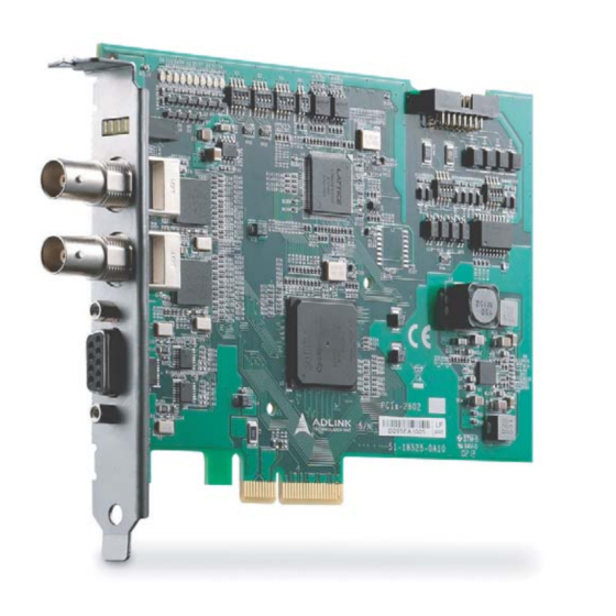
PCIe-2602 Figure 1-2: PCIe-2602 Board Layout D I/O RS-485 Table 1-1: Board Layout Legend I/O and indicator panel elements are labeled as follows Figure 1-3: I/O & Indicator Panel Introduction... -
Page 18: Sdi Connector
SDI Connector Figure 1-4: SDI Connector Function Type SDI signal Input SDI signal GND Reference ground Table 1-2: SDI Connector Pin Assignment 1.5.2 RS-485 Connector The PCIe-2602 RS-485 connector is a DSUB-9 male configura- tion. Figure 1-5: RS-485 Connector Introduction... -
Page 19: Di/O (Digital Input/Output) Connector
Reference ground RS-485 Table 1-3: Connector Pin Assignment 1.5.3 DI/O (Digital Input/Output) Connector The PCIe-2602 DI/O connector is a 16 pin-header configuration. Figure 1-6: DI/O Connector Function Type DI3- Digital Input channel 3 invert pin DI0+ Digital Input channel 0 non-invert pin... -
Page 20: Table 1-4: D I/O Connector Pin Assignments
Function Type DI2+ Digital Input channel 2 non-invert pin DI0- Digital Input channel 0 invert pin DI3+ Digital Input channel 3 non-invert pin Digital Output channel 0 Digital Ground Digital Output channel 1 Digital Ground Digital Output channel 2 Digital Output Darlington IC clamping Clamp voltage Digital output channel 3... -
Page 21: Figure 1-7: D-Sub Connector Cable
PCIe-2602 External access to the DI/O connector can be provided using ADLINK's separately available D-sub connector cable with exter- nal bracket (ADLINK part number: 30-25013-0000). Figure 1-7: D-sub Connector Cable Introduction... -
Page 22: Figure 1-8: D-Sub Connector Cable Exterior Connector
Figure 1-8: D-sub Connector Cable Exterior Connector Function Type DI3- Input DI0+ Input DI2- Input DI1+ Input DI1- Input DI2+ Input DI0- Input DI3+ Input Output DO Ground Introduction... -
Page 23: Led Indicators
PCIe-2602 Function Type Output DO Ground Output DO clamp DO Power Output Table 1-5: D-sub Connector Cable Exterior Connector Pin Assignments 1.5.4 LED Indicators Four LED indicators on the I/O panel indicate SDI signal connec- tion and status. Figure 1-9: LED Indicators LEDs 0 and 1 indicate status of vertical synchronization signals, while 2 and 3 confirm data verification, as follows. -
Page 24: Table 1-7: Leds 1 And 3 Indicator Legend
Table 1-7: LEDs 1 and 3 Indicator Legend If a signal is received but unidentified, please check the SDI signal format according to Section 1.4.2 Video & Audio. The PCIe-2602 may support resolutions not listed, please contact NOTE: NOTE: ADLINK FAE for support. -
Page 25: Switch Settings
PCIe-2602 1.5.5 Switch Settings Switches for digital I/O and card ID settings, allowing identification of individual cards in a multi-card system, are located as follows. Figure 1-10: Switch Locations Switch Function Card ID Settings S4-S5 Digital I/O Settings Table 1-8: Switch Functions... -
Page 26: Table 1-9: Card Id Switch Settings (S1)
Card ID Slider 1 Slider 2 Slider 3 Slider 4 Table 1-9: Card ID Switch Settings (S1) DI Channel DI Status Slider Setting Pulled high to +5V Pulled high to +5V Pulled high to +5V Pulled high to +5V Table 1-10: D I/O Switch Settings (S4) Introduction... -
Page 27: Digital I/O Connections
Pulled high to +5V Pulled high to +5V Table 1-11: D I/O Switch Settings (S5) 1.5.6 Digital I/O Connections Function block diagrams and connection examples for digital I/O settings follow. Digital Input Figure 1-11: PCIe-2602 Digital Input Functional Block Diagram Introduction... -
Page 28: Figure 1-12: Sinking Di: Slider # Of Switch 4 Off
In the following, varying situations are illustrated in which channel # of digital input is connected, where # is 0 to 3. PCIe-2602 +3.3V DI IN# + (From VCC from user Connector) DI#(To FPGA) DI IN# - (From DO from user... -
Page 29: Figure 1-13: Sourcing Di: Slider # Of Switch 4 Is On
PCIe-2602 PCIe-2602 +3.3V DI IN# +(From Connector) DI#(To FPGA) DI IN# - (From DO from user Connector) DO Status API (DI Status) from User High Z Figure 1-13: Sourcing DI: Slider # of Switch 4 is ON Introduction... -
Page 30: Figure 1-14: Pcie -2602 Digital Output Functional Block Diagram
Digital Output Figure 1-14: PCIe -2602 Digital Output Functional Block Diagram In the following, varying situations are illustrated in which channel # of digital output is connected, where # is 0 to 3. Introduction... -
Page 31: Figure 1-15: Sinking Do: Slider # Of Switch 5 Is Off
PCIe-2602 PCIe-2602 Clamp User VCC User Device Load Darlington Driver User DI DO# (From FPGA) DO Out# (To connector) DO Out# to API (DO Output) Connector Low(0V) High Z Figure 1-15: Sinking DO: Slider # of Switch 5 is OFF... -
Page 32: Rs-485 Connection
Figure 1-16: Sourcing DO: Slider # of Switch 5 is ON 1.5.7 RS-485 Connection PCIe-2602 supports RS-485 protocol To avoid signal reflections, each bus segment must be blanked at its physical beginning and end with the characteristic impedance. A resistor, Rt, is installed for this purpose, with – 130Ω ± 2% the... -
Page 33: Figure 1-17: Rs-485 Connection
PCIe-2602 recommended value. Detailed connection of the Rt is as follows. PCIe-2602 supports BUS topology. User device PCIe-2602 (Rt) Figure 1-17: RS-485 Connection Introduction... - Page 34 This page intentionally left blank. Introduction...
-
Page 35: Getting Started
PCI express bus. 1. Remove the computer cover according to the computer manual.. A vacant PCI express slot is required for installation of the PCIe-2602 module; if none is available, remove a PCI express board and note the slot number. NOTE: NOTE: 2. - Page 36 7. Power up the computer. The PCIe-2602 can be installed in a PCI Express x4, x8, or pcie PCIe x16 slot. NOTE: NOTE: Getting Started...
-
Page 37: A Appendix: Viewcreator Pro Utility
ViewCreator Pro provides 32/64-bit compatibility under Windows XP/Vista/7 Direct- Show driver Access to and configuration of PCIe-2602 cards Video picture adjustment Image file (BMP or JPG) viewing and saving Access to general purpose I/O Figure A-1: ViewCreator Pro Interface... -
Page 38: Devices Panel
The ViewCreator Pro interface provides a variety of panels and toolbars, allowing comprehensive task performance in all areas of function. A.0.1 Devices Panel Figure A-2: Devices Panel Panel Item Function Lists cards on the local system supported by Local ViewCreator Pro Active The device to which all operations will apply Device... -
Page 39: Tool Panel
PCIe-2602 A.0.2 Tool Panel Tool Button Function ContinueGrab Toggles continuous acquisition of images SnapShot Captures a single image Hide/Show Image Toggles display of the image FitSize Resizes the image to fit the display area OriginalSize Restores the image to original size... -
Page 40: Table A-2: Tool Panel Controls
Tool Button Function Opens a window showing the HSI values along HSI Conversion the selected line on the image Transforms the image to YCbCr color space, YCbCr Enable toggling YCbCr Enable/Y Enable (CbCr=128)/ CbCr Enable (Y=0)/YCbCr Disable Toggles No Flip/Flip X axis (horizontal)/Flip Y Image Flip axis (vertical) Toggles Record function... - Page 41 PCIe-2602 ViewCreator Pro Utility...
- Page 42 When acquisition is complete, the background color of the win- dow changes to black. X-axis size is the width of the entire image. ViewCreator Pro Utility...
- Page 43 PCIe-2602 If the image is chromatic, three curves, individually represent- ing red, green, and blue are shown. ViewCreator Pro Utility...
- Page 44 If the color format of captured image is YUV, three curves indi- vidually representing Y, U, and V are shown. ViewCreator Pro Utility...
-
Page 45: Table A-3: Focusvalue Tools
PCIe-2602 FocusValue Tools Tool Button Function Increases closeup on the area in the FocusValue window bound by the green Zoom In rectangle, which can be resized by dragging the side borders Displays slope of the line for the area in the... -
Page 46: Display Panel
A.0.3 Display Panel Captured images are displayed on this panel as shown. A.0.4 Status Panel Displays image acquisition, signal, and image statistics, as shown. Figure A-3: Status Panel Top Row (L to R) Bottom Row (L to R) Selected port and channel Red component statistics Cursor position Pixel value... -
Page 47: Display Menu
PCIe-2602 A.0.5 Display Menu Allows selection of desired video format based on SDI(BNC). The SDI menu is shown open as an example. Figure A-4: SDI Display Menu Format Resolution 525i 29.97/30 fps 720 x 486 625i 25 fps 720 x 576... -
Page 48: Color Format Menu
Format Resolution 1080i 25 fps 1920 x 1080 1080i 29.97/30 fps 1920 x 1080 1080p 23.98/24 fps 1920 x 1080 1080p 25 fps 1920 x 1080 1080p 30 fps 1920 x 1080 1080p 50 fps 1920 x 1080 1080p 59.97/60 fps 1920 x 1080 Table A-5: SDI (BNC) Available Formats A.0.6... -
Page 49: Image Size Menu
PCIe-2602 A.0.8 Image Size Menu Top-down Enables top-down image display. Top-down function, when enabled, may improve capture effi- cency in computers experiencing low frame rate due to perfor- mance. Auto Detect Automatically detects image resolution A.0.9 Tool Menu DI/O Sets and retrieves digital input/output status, select digital output and digital input conditions. -
Page 50: Help Menu
Figure A-5: DI/O Dialog A.0.10 Help Menu About Device Displays card ID, hardware version, firmware version, driver ver- sion, and utility version information. ViewCreator Pro Utility... -
Page 51: Figure A-6: About Device Dialog
PCIe-2602 Figure A-6: About Device Dialog ViewCreator Pro Utility... - Page 52 This page intentionally left blank. ViewCreator Pro Utility...
-
Page 53: B Appendix: Pcie-2602 Benchmark
PCIe-2602 Appendix B PCIe-2602 Benchmark PCIe-2602 delivers 2-CH 1080P/60 fps raw video data requiring PCIe X4 or more. If bandwidth is insufficient, abnormal images may be generated or frames lost. In some systems, the bandwidth of PCIe slots may be shared. When frame capture rate deviates from that expected, check the PCIe slot setting in the computer user manual or BIOS. -
Page 54: Test 2
Rate (fps) B.2.4 Test 4 Motherboard ASUS P6TSE ® Intel Core™ i7 920 2.67GHz Memory 2GB X 1 Win7 Ultimate 32 bit Input signal 1080p 60fps,YUV 4:2:2, 10 bit Card ID 0 (PCIe x16 slot) 1 (PCIe x16 slot) PCIe-2602 Benchmark... -
Page 55: Test 5
Intel® Core™ i7 950 3.07 GHz Memory 2GB X 2 Win7 Pro 32 bit Input signal 1080p 60fps,YUV 4:2:2, 10 bit Card ID 0 (PCIe x16 slot) 1 (PCIe x16 slot) 2 (PCIe x16 slot) Channel Number Captured Frame Rate (fps) PCIe-2602 Benchmark... - Page 56 This page intentionally left blank. PCIe-2602 Benchmark...
-
Page 57: Important Safety Instructions
PCIe-2602 Important Safety Instructions For user safety, please read and follow all instructions, WARNINGS, CAUTIONS, and NOTES marked in this manual and on the associated equipment before handling/operating the equipment. Read these safety instructions carefully. Keep this user’s manual for future reference. - Page 58 Never attempt to fix the equipment. Equipment should only be serviced by qualified personnel. A Lithium-type battery may be provided for uninterrupted, backup or emergency power. Risk of explosion if battery is replaced with one of an incorrect type. Dispose of used batteries appropriately. WARNING: Equipment must be serviced by authorized technicians when:...
-
Page 59: Getting Service
5215 Hellyer Avenue, #110, San Jose, CA 95138, USA Tel: +1-408-360-0200 Toll Free: +1-800-966-5200 (USA only) Fax: +1-408-360-0222 Email: info@adlinktech.com ADLINK Technology (China) Co., Ltd. Address: (201203) 300 Fang Chun Rd., Zhangjiang Hi-Tech Park, Pudong New Area, Shanghai, 201203 China Tel: +86-21-5132-8988 Fax:... - Page 60 84 Genting Lane #07-02A, Cityneon Design Centre, Singapore 349584 Tel: +65-6844-2261 Fax: +65-6844-2263 Email: singapore@adlinktech.com ADLINK Technology Singapore Pte. Ltd. (Indian Liaison Office) Address: 1st Floor, #50-56 (Between 16th/17th Cross) Margosa Plaza, Margosa Main Road, Malleswaram, Bangalore-560055, India Tel: +91-80-65605817, +91-80-42246107 Fax: +91-80-23464606 Email: india@adlinktech.com...
Need help?
Do you have a question about the PCIe-2602 and is the answer not in the manual?
Questions and answers