Table of Contents
Advertisement
Quick Links
Advertisement
Table of Contents

Related Manuals for Multitech MTC-C2


Summary of Contents for Multitech MTC-C2
- Page 1 ® MultiConnect Cell User Guide...
- Page 2 Contacting Multi-Tech Knowledge Base The Knowledge Base provides immediate access to support information and resolutions for all Multi-Tech products. Visit http://www.multitech.com/kb.go. Support Portal To create an account and submit a support case directly to our technical support team, visit: https://support.multitech.com.
-
Page 3: Table Of Contents
About the MultiConnect Cell Modem........................... 5 Documentation ................................6 Descriptions of LEDs..............................6 Side Panels ..................................7 Specifications ................................7 Power Draw MTC-C2 ..............................9 Dimensions.................................. 10 Cellular Information............................... 12 Antenna..................................12 CDMA Antenna Information ............................12 CDMA Antenna Requirements/Specifications ......................12 Installing and Using the Device .......................... - Page 4 CONTENTS Testing Serial Ports..............................20 Create a PPP Connection ............................20 Example..................................20 Configuring and Communicating with Your Device....................22 Interacting with Your Device Overview ........................22 Before You Begin................................. 22 Using Command Mode and Online Data Mode......................22 Verifying Signal Strength............................. 23 Example ..................................
-
Page 5: Product Overview
Product Overview About the MultiConnect Cell Modem The MultiConnect® Cell cellular MTC-C2 modems are ready-to-deploy, standalone dual-band CDMA 1 x RTT modems that provide wireless data communication. The modems integrate seamlessly with virtually any application, and are useful for automated applications, such as remote diagnostics and remote monitoring. They are available with RS-232 or USB connectors. -
Page 6: Documentation
Guide schematics, and general device information. EV-DO EV3 and CDMA C2 AT You can configure the MTC-C2 device using the CDMA C2 AT Commands. These Commands Reference Guide commands are documented in the Reference Guide part number S000546. Descriptions of LEDs Devices that have a serial connector have the following LEDs: ■... -
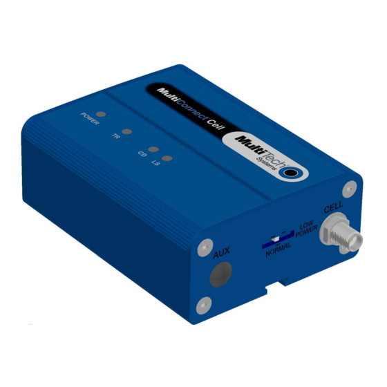
Page 7: Side Panels
The device has connectors on either side. The figures that follow show the side panels. Note: The power-saving switch—which appears with the NORMAL and LOW POWER labels—is included only on models that have a serial connector. Specifications MTC-C2 Category Description General Performance... - Page 8 PRODUCT OVERVIEW Category Description Connectors Cellular Female SMA RS-232 Mini-B, USB 2.0 high speed or better Power 2.5 mm miniature screw-on, RS-232 models Power Requirements Voltage Serial: 7 V to 32 V DC USB 5 V Physical Description Dimensions Dimensions are shown in the section “Dimensions” that follows. Weight 8.2 ounces or 230 grams Environment...
-
Page 9: Power Draw Mtc-C2
PRODUCT OVERVIEW Power Draw MTC-C2 5 volts Cellular call box Average measured Peak TX amplitude Total inrush charge connection no data current (amps) at current (amps) measured in (amps) maximum power MilliCoulombs (mC) US Cellular 800 Mhz 0.050 0.520 0.572 1.26... -
Page 10: Dimensions
PRODUCT OVERVIEW Dimensions ® MultiConnect Cell User Guide... - Page 11 PRODUCT OVERVIEW ® MultiConnect Cell User Guide...
-
Page 12: Cellular Information
CELLULAR INFORMATION Cellular Information Antenna The antenna intended for use with this unit meets the requirements for mobile operating configurations and for fixed mounted operations, as defined in 2.1091 and 1.1307 of the FCC rules for satisfying RF exposure compliance. If an alternate antenna is used, consult user documentation for required antenna specifications. -
Page 13: Installing And Using The Device
INSTALLING AND USING THE DEVICE Installing and Using the Device Installing the Device Connect a suitable antenna to the antenna connector. If you are using the serial version of this device: Connect the DE9 connector (9-pin) of the RS-232 cable to the RS-232 connector on the device, then connect the other end to the serial port on the other desired device. -
Page 14: Usb Cable Recommendations
INSTALLING AND USING THE DEVICE To have the device enter sleep mode, set DTR to inactive (off) on the RS-232 interface. The clear to send (CTS) signal is off when the device is in sleep mode. USB Cable Recommendations If your device has a USB connector, to avoid enumeration or power issues: ■... -
Page 15: Installing Device Drivers
INSTALLING DEVICE DRIVERS Installing Device Drivers Installing on Linux The Linux OS includes a generic USB driver for modems supporting CDC/ACM. Multi-Tech tested the following Linux operating systems and all used port . If your system has another device using this port, your port numbers may be different. -
Page 16: Windows Notes
Downloading the Windows USB Driver If you haven't downloaded the driver: Go to the Multi-Tech Support page, www.multitech.com/support.go and select your product from the Product Families drop down list. Click Drivers. Extract the files to your computer. -
Page 17: Installing On Windows Xp
INSTALLING DEVICE DRIVERS Installing on Windows XP Note: If you previously installed USB drivers for this device, uninstall them before installing or re-installing this driver. Uninstall all existing drivers for this device. Refer to Uninstall Windows Drivers for details. Before you connect the device (disconnect the device if you connected it): Click Next and follow the instructions in the installation wizard. -
Page 18: Uninstalling Windows Drivers
INSTALLING DEVICE DRIVERS Uninstalling Windows Drivers Note: Disconnect the device before uninstalling drivers. Windows 8 To uninstall drivers from Windows 8: Open Windows Programs and Features. Uninstall all Telit modems, ports, and USB drivers. Windows 7 or Vista To uninstall drivers from Windows 7 or Vista: Open Programs and Features from the Windows Control Panel. -
Page 19: Antenna And Activation Information
Verizon Wireless. Before you can use the modem, you must set up a cellular data account with your service provider. Each service provider has its own process for adding devices to their network. Refer to Multi-Tech's Cellular Activation site http://www.multitech.com/activation.go for step-by-step instructions on activating your cellular modem with your service provider. -
Page 20: Using Linux
USING LINUX Using Linux Shell Commands Testing Serial Ports To test the serial ports created by the driver, type in a shell: Note: Sending ATE0 is required, to avoid issues in the terminal output. It prevents the sending/receiving spurious characters to/from the modem when used with the Linux commands “echo” and “cat” Create a PPP Connection Most recent Linux distributions have GUI tools for creating PPP connections;... - Page 21 USING LINUX ipcp-accept-remote # Keep modem up even if connection fails #persist # Hardware flow control crtscts # Ask the peer for up to 2 DNS server addresses usepeerdns # No ppp compression novj nobsdcomp novjccomp nopcomp noaccomp # For sanity, keep a lock on the serial line lock # Show password in debug messages show-password...
-
Page 22: Configuring And Communicating With Your Device
CONFIGURING AND COMMUNICATING WITH YOUR DEVICE Configuring and Communicating with Your Device Interacting with Your Device Overview This section describes how to use AT commands to interact with your device. Using terminal software such as Kermit, you can issue AT commands to communicate with and configure your modem. The AT commands let you establish, read and modify device parameters and help you control how the device operates. -
Page 23: Verifying Signal Strength
CONFIGURING AND COMMUNICATING WITH YOUR DEVICE ■ Flow control: hardware To confirm you are communicating with the device: ■ Type AT and press Enter. If the device responds with OK, you are communicating with the device. Verifying Signal Strength To verify the device signal strength, enter: AT+CSQ The command indicates signal quality, in the form: +CSQ: <rssi>,<ber>... -
Page 24: Example
CONFIGURING AND COMMUNICATING WITH YOUR DEVICE Example A example response to AT+CSQ: +CSQ: 15,1 Checking Network Registration for EV2 and C2 To verify that a device is registered on the network, enter: AT!STATUS The device returns several lines of modem status information. The second to last line indicates either: Modem has registered. -
Page 25: Configuring Device As Udp Client To Connect To Udp Server
CONFIGURING AND COMMUNICATING WITH YOUR DEVICE AT+CSQ Verify device is registered on the cellular network. Enter: AT!STATUS Configure socket parameters Enter: AT#SCFG=1,1,300,240,600,50 Activate context one Enter: AT#SGACT=1,1 Set firewall rule to accept connections: AT#FRWL=1,"###.##.###.#","###.##.###.#" where ###.##.###.# represents the IP range. For example: AT#FRWL=1,"204.26.122.1","204.26.122.255"... -
Page 26: Configuring Device As Udp Listener To Accept Udp Client Connections
CONFIGURING AND COMMUNICATING WITH YOUR DEVICE Verify device is registered on the cellular network. Enter: AT!STATUS Configure socket parameters Enter: AT#SCFG=1,1,300,240,600,50 Activate context one Enter: AT#SGACT=1,1 Create UDP connection to Server port Enter: AT#SD=1,1,####,"###.##.###.##" where #### is the server port and ###.##.###.## is the IP number. The device responds with OK, which indicates a successful connection. -
Page 27: Transferring Ftp File To Ftp Server
CONFIGURING AND COMMUNICATING WITH YOUR DEVICE Set connection ID 1 for UDP listening mode on port 7000. Enter: AT#SLUDP=1,1,7000 The device responds with and unsolicited indication that a host is trying to connect to connection ID 1 on port 7000. SRING: 1 Accept incoming connection ID 1 Enter:... -
Page 28: Downloading File From Ftp Server
CONFIGURING AND COMMUNICATING WITH YOUR DEVICE Enter: AT#FTPPUT="file.txt" The device responds with: CONNECT Send the file through the device. Closing the FTP Data Connection When you finish sending the file: Enter the escape sequence. Enter: The device responds with: NO CARRIER Close the FTP connection. -
Page 29: Reading, Writing And Deleting Messages
CONFIGURING AND COMMUNICATING WITH YOUR DEVICE AT#FTPCWD="folder1" Enter the file name. Enter: AT#FTPGET="filename.txt" where filename.txt is the file you want to download. The device responds with: CONNECT The file is received through the device. The device responds with: NO CARRIER The data connection closes automatically when the file sending ends. -
Page 30: Deleting Messages
CONFIGURING AND COMMUNICATING WITH YOUR DEVICE Enter: AT+CMGS="##########" >Your message here where ########## is the recipient's number. Send the message. Enter CTRL+Z. The device responds: +CMGS: 255 For example: AT+CMGF=1 AT+CMGS="6155554563" > How are you? <CTRL+Z to send> +CMGS: 255 Deleting Messages To delete one text message, enter: AT+CMGD=I,#... -
Page 31: Regulatory Information
REGULATORY INFORMATION Regulatory Information 47 CFR Part 15 Regulation Class B Devices This equipment has been tested and found to comply with the limits for a Class B digital device, pursuant to part 15 of the FCC Rules. These limits are designed to provide reasonable protection against harmful interference in a residential installation. -
Page 32: Reach Statement
REGULATORY INFORMATION REACH Statement Registration of Substances After careful review of the legislation and specifically the definition of an “article” as defined in EC Regulation 1907/2006, Title II, Chapter 1, Article 7.1(a)(b), it is our current view Multi-Tech Systems, Inc. products would be considered as “articles”. -
Page 33: Information On Hs/Ts Substances According To Chinese Standards
REGULATORY INFORMATION Information on HS/TS Substances According to Chinese Standards In accordance with China's Administrative Measures on the Control of Pollution Caused by Electronic Information Products (EIP) # 39, also known as China RoHS, the following information is provided regarding the names and concentration levels of Toxic Substances (TS) or Hazardous Substances (HS) which may be contained in Multi-Tech Systems Inc. -
Page 34: Information On Hs/Ts Substances According To Chinese Standards (In Chinese)
REGULATORY INFORMATION Information on HS/TS Substances According to Chinese Standards (in Chinese) 依 依 照 照 中 中 国 国 标 标 准 准 的 的 有 有 毒 毒 有 有 害 害 物 物 质 质 信 信 息 息 根据中华人民共和国信息产业部...
Need help?
Do you have a question about the MTC-C2 and is the answer not in the manual?
Questions and answers