Multitech MultiConnect Cell 100 Series User Manual
Hide thumbs
Also See for MultiConnect Cell 100 Series:
- Quick start manual ,
- User manual (33 pages) ,
- Quick start (2 pages)
Table of Contents
Advertisement
Quick Links
Advertisement
Table of Contents

Related Manuals for Multitech MultiConnect Cell 100 Series


Summary of Contents for Multitech MultiConnect Cell 100 Series
- Page 1 ® MultiConnect Cell MTC-MNK1 User Guide...
- Page 2 Legal Notices The MultiTech products are not designed, manufactured or intended for use, and should not be used, or sold or re-sold for use, in connection with applications requiring fail-safe performance or in applications where the failure of the products would reasonably be expected to result in personal injury or death, significant property damage, or serious physical or environmental damage.
-
Page 3: Table Of Contents
CONTENTS Contents Chapter 1 – Product Overview ..........................5 About the MultiConnect Cell Modem........................... 5 Product Build Options ..............................5 Documentation ................................5 Dimensions..................................6 Serial.................................... 6 USB....................................7 LED Descriptions ................................8 Side Panels ..................................8 MTC-MNK1 Specifications............................. 9 RS-232 9-Pin Female Connector .......................... - Page 4 CONTENTS Example ..................................18 Checking Network Registration........................... 18 Sending and Receiving Data............................19 Connecting Device to TCP Server as TCP Client ......................19 Configuring Device as UDP Listener to Accept UDP Client Connections ..............20 Configuring Device as UDP Client to Connect to UDP Server ................... 21 Transferring FTP File to FTP Server ...........................
-
Page 5: Chapter 1 - Product Overview
LTE Cat M1 Modem, RS-232 interface with KR Accessory Kit (Korea) MTC-MNK1-B03 LTE Cat M1 Modem, USB interface with USB Accessory Kit (Korea) Documentation The following documentation is available on the product page of the MultiTech website (https://www.multitech.com/brands/multiconnect-cell-100-series). Document Description MultiConnect Cell User This document. -
Page 6: Dimensions
PRODUCT OVERVIEW Dimensions Serial ® MultiConnect Cell MTC-MNK1 User Guide... -
Page 7: Usb
PRODUCT OVERVIEW ® MultiConnect Cell MTC-MNK1 User Guide... -
Page 8: Led Descriptions
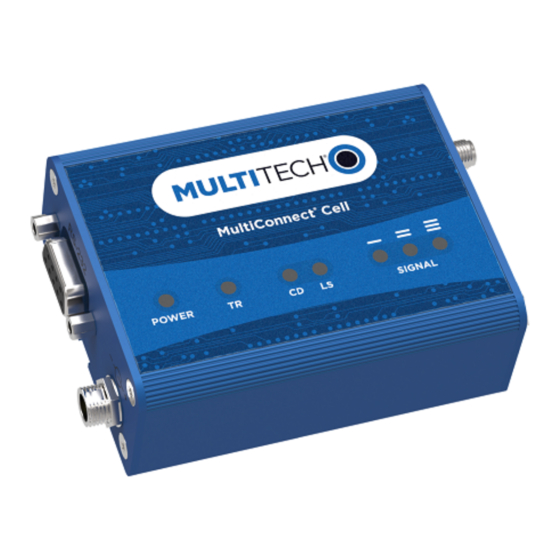
PRODUCT OVERVIEW LED Descriptions The top panel contains the following LEDs: Power and Terminal Ready LEDs—The Power LED indicates that DC power is present and the TR LED blinks when the unit is functioning normally. Modem LEDs—Two modem LEDs indicate carrier detection and link status (for serial units only). Prog. -
Page 9: Mtc-Mnk1 Specifications
PRODUCT OVERVIEW MTC-MNK1 Specifications Category Description General Standards LTE UE Category M1/NB1, 3GPP release 13 compliant USB Interface is CDC-ACM compliant TCP/IP Functions FTP, SMTP, SSL, TCP, UDP Frequency Bands 4G: 1800 (B3) / 850 (B5) Speed Data Speed LTE Cat M1: Up to 375 Kbps uplink / Up to 300 Kbps downlink LTE Cat NB1: Up to 62.5 Kbps uplink/ Up to 21 Kbps downlink. -
Page 10: Rs-232 9-Pin Female Connector
PRODUCT OVERVIEW Category Description Certifications and Compliance EMC Compliance Radio Compliance Safety Compliance IEC 60950-1 2nd ED RS-232 9-Pin Female Connector Abbreviation Description In/Out Carrier Detect Receive Transmit Data Terminal Ready Ground Data Set Ready Request to Send Clear to Send Ring Indicator Power Measurements Multi-Tech Systems, Inc. -
Page 11: Usb Model: Mtc-Mnk1-B03 Power Draw
PRODUCT OVERVIEW Radio Sleep mode Cellular call Average Average TX Total inrush Total inrush Protocol current, measured pulse charge, in charge connected to connection, no current at amplitude duration during wireless data maximum current power-up power 12 Volts LTE 836.5 7 mA 25 mA 87 mA... -
Page 12: Chapter 2 - Safety Warnings
SAFETY WARNINGS Chapter 2 – Safety Warnings Radio Frequency (RF) Safety Due to the possibility of radio frequency (RF) interference, it is important that you follow any special regulations regarding the use of radio equipment. Follow the safety advice given below. Operating your device close to other electronic equipment may cause interference if the equipment is inadequately protected. -
Page 13: Chapter 3 - Installing And Using The Device
INSTALLING AND USING THE DEVICE Chapter 3 – Installing and Using the Device Installing a SIM Card This model requires a SIM card, which is supplied by your service provider. To install the SIM card: Locate the SIM card slot on the side of the modem. The slot is labeled SIM. Slide the SIM card into the SIM card slot with the contact side facing down as shown. -
Page 14: Placing Serial Devices In Power Save Mode
If possible, use a USB port that connects directly to the motherboard rather than a USB port with added cabling inside the computer chassis. Use USB 3.0 ports if available. These ports are typically rated for more current. You can order the USB cable through MultiTech. The part number is CA-USB-A-MINI-B-3 Powering Down Your Device CAUTION: Failing to properly power down the device before removing power may corrupt your device's file system. -
Page 15: Mounting Device To Flat Surface
INSTALLING AND USING THE DEVICE Note: If you send AT#SHDN and do not remove power, the radio restarts after 60 seconds. Mounting Device to Flat Surface Locate the groove on the bottom of the device. Slide the mounting bracket through the groove. To secure the bracket to the desired surface, place and tighten two screws in the holes on either end of the mounting bracket. -
Page 16: Chapter 4 - Antenna And Activation Information
Account Activation for Cellular Devices Some MultiTech devices are pre-configured to operate on a specific cellular network. To use the device, you must set up a cellular data account with your service provider. Each service provider has its own process for adding devices to their network. -
Page 17: Chapter 5 - Configuring And Communicating With Your Device
CONFIGURING AND COMMUNICATING WITH YOUR DEVICE Chapter 5 – Configuring and Communicating with Your Device Before Using the Device Before using the device: Install any drivers. Refer to the separate driver installation guide for your device. Power up your device and ensure it is connected to your computer that issues AT commands. Note: Wait 10 seconds after power-up before issuing any AT commands. -
Page 18: Example
CONFIGURING AND COMMUNICATING WITH YOUR DEVICE +CSQ: <rssi>,<sq> Where: <rssi> Received signal strength indication. (-113) dBm or less (-111) dBm 2-30 (-109) dBm - (-53) dBm / 2 dBm per step (-51) dBm or greater Not known or not detectable <sq>... -
Page 19: Sending And Receiving Data
CONFIGURING AND COMMUNICATING WITH YOUR DEVICE AT+CEREG?: 0,5 The device is registered. If the device returns: AT+CEREG?: 0,2 The device is in a network searching state. Sending and Receiving Data Connecting Device to TCP Server as TCP Client AT+CGDCONT=1,"IPV4V6","apnname" where apnname is the APN your cellular provider assigned to your SIM card. Bring up Data Connection Using Internal IP stack Enter: Verizon:... -
Page 20: Configuring Device As Udp Listener To Accept Udp Client Connections
CONFIGURING AND COMMUNICATING WITH YOUR DEVICE AT#SGACT=1,0 The device responds with OK. Configuring Device as UDP Listener to Accept UDP Client Connections To configure the device as a UDP client: Check signal strength. Enter: AT+CSQ Verify device is registered on the cellular network. Enter: Should return: +CEREG: 0,1 or +CEREG: 0,5... -
Page 21: Configuring Device As Udp Client To Connect To Udp Server
CONFIGURING AND COMMUNICATING WITH YOUR DEVICE To close Socket 1, enter: AT#SH=1 To close the data connection, enter: Verizon: AT#SGACT=3,0 Other Networks: AT#SGACT=1,0 The device responds with OK. Configuring Device as UDP Client to Connect to UDP Server Configure and Connect the Device To configure the device as a UDP client: Check signal strength. -
Page 22: Transferring Ftp File To Ftp Server
CONFIGURING AND COMMUNICATING WITH YOUR DEVICE To close Socket 1, enter: AT#SH=1 To close the data connection,enter: Verizon: AT#SGACT=3,0 Other Networks: AT#SGACT=1,0 The device responds with OK. Transferring FTP File to FTP Server To connect to FTP server and upload files: Check signal strength. -
Page 23: Downloading File From Ftp Server
CONFIGURING AND COMMUNICATING WITH YOUR DEVICE Send the file through the device. Closing the FTP Data Connection After the file is sent: Enter the escape sequence. Enter: The device responds with: NO CARRIER Close the FTP connection. Enter: AT#FTPCLOSE Close the PPP data connection. Enter: Verizon: AT#SGACT=3,0... -
Page 24: Reading, Writing And Deleting Messages
CONFIGURING AND COMMUNICATING WITH YOUR DEVICE AT#FTPOPEN="###.##.###.#","username","password",0 where ###.##.###.# is the IP address and the username and password for the FTP server. Configure file transfer type. Enter: AT#FTPTYPE=# where # is 0 for binary or 1 for ASCII. If required, change the working directory to "folder1". Enter: AT#FTPCWD="folder1"... -
Page 25: Sending Text Messages
CONFIGURING AND COMMUNICATING WITH YOUR DEVICE Read message. Enter: AT+CMGR=1 Example response: +CMGR: "REC UNREAD","0001112222","","20161006135126" How are you? Where 0001112222 is the recipient phone number and 20161006135126 is received data in the format YYYYMMDDHHMMSS. Sending Text Messages To send a text message in text mode: Check signal strength. -
Page 26: Deleting Messages
CONFIGURING AND COMMUNICATING WITH YOUR DEVICE > How are you? <CTRL+Z to send> +CMGS: 255 Where 0001112222 is the phone number. Deleting Messages To delete one text message, enter: AT+CMGD=1,# where 1 is the index in the select storage and # is the delflag option. Enter: Deletes message in the specified index. -
Page 27: Chapter 6 - Regulatory Information
REGULATORY INFORMATION Chapter 6 – Regulatory Information Korea Regulatory Information It is verified that foregoing equipment has been registered under the Clause 3, Article 58-2 of Radio Waves Act. ® MultiConnect Cell MTC-MNK1 User Guide... -
Page 28: Restriction Of The Use Of Hazardous Substances (Rohs)
2015/863 of the European Parliament (Restriction of the use of certain Hazardous Substances in electrical and electronic equipment - RoHS 3). These MultiTech products do not contain the following banned chemicals Lead, [Pb] < 1000 PPM Mercury, [Hg] <... -
Page 29: Instructions For Disposal Of Weee By Users In The European Union
Substances) complements the WEEE Directive by banning the presence of specific hazardous substances in the products at the design phase. The WEEE Directive covers all MultiTech products imported into the EU as of August 13, 2005. EU-based manufacturers, distributors, retailers and importers are obliged to finance the costs of recovery from municipal collection points, reuse, and recycling of specified percentages per the WEEE requirements. -
Page 30: Information On Hs/Ts Substances According To Chinese Standards
REGULATORY INFORMATION Information on HS/TS Substances According to Chinese Standards In accordance with China's Administrative Measures on the Control of Pollution Caused by Electronic Information Products (EIP) # 39, also known as China RoHS, the following information is provided regarding the names and concentration levels of Toxic Substances (TS) or Hazardous Substances (HS) which may be contained in Multi-Tech Systems Inc. -
Page 31: Information On Hs/Ts Substances According To Chinese Standards (In Chinese)
REGULATORY INFORMATION Information on HS/TS Substances According to Chinese Standards (in Chinese) 依 依 照 照 中 中 国 国 标 标 准 准 的 的 有 有 毒 毒 有 有 害 害 物 物 质 质 信 信 息 息 根据中华人民共和国信息产业部... -
Page 32: Chapter 7 - Using Connection Manager
Click Connection Manager. Open or unzip the Connection Manager file and run the installer (.msi file). In the MultiTech Connection Manager Setup Wizard, read the end-user license agreement and check I accept the terms in the License Agreement. Click Next to have the installer automatically disable the native WWAN AutoConfig service in Windows. -
Page 33: Setting Up A Serial Device In Windows Device Manager
To specify a folder for Connection Manager, use the default folder or click Change to browse to the folder you want to use. Click Install. A separate wizard opens for installing Telit drivers. Some MultiTech devices use embedded modules from Telit Wireless Solutions to provide cellular connectivity; these devices require Telit drivers. Select Complete setup type. - Page 34 USING CONNECTION MANAGER In the Add Hardware Wizard: Click Next. Select Install the hardware that I manually select from a list, then click Next. Select Modems, then click Next. Check Don't detect my modem; I will select it from a list, then click Next. Select Standard Modem Types, then select Standard 33600 bps Modem on the right.
-
Page 35: Connecting A Device
USING CONNECTION MANAGER Connecting a Device Before You Begin Make sure that your device is connected to the computer where Connection Manager is installed. Set up the device in Device Manager. Refer to Setting Up a Serial Device in Windows Device Manager. -
Page 36: Uninstalling Connection Manager
The steps above describe how to uninstall Connection Manager using Control Panel. You can also uninstall the application by using the installer file (.msi). Double-click the file, in the MultiTech Connection Manager Setup Wizard, click Next, and then select Remove on the next two pages. -
Page 37: Connection Manager User Interface
USING CONNECTION MANAGER Connection Manager User Interface Connection Manager consists of the following tabs: Main Settings Connection Details Terminal Charts Main tab The Main tab displays the following: Status of device connection: Searching, Connecting, Connected, Disconnecting, or Disconnected The action button, which changes according to the current device connection status: Detect, Connect, or Disconnect Signal strength bars and percentage indicator (only when connection to the carrier's network is established) Note:... -
Page 38: Settings Tab
USING CONNECTION MANAGER Connection statistics: download and upload speeds, amount of traffic sent and received (only when connection to the carrier's network is established) The keep-alive check status and when the last ping response was received if Enable keep-alive check is checked on the Connection tab. -
Page 39: Troubleshooting
USING CONNECTION MANAGER Troubleshooting Serial COM port is not available in the Serial Modem Settings Close Connection Manager and reopen it. Device is not detected ("No Device") After following the steps to activate your device, the Main tab still indicates "No Device." Try the following steps: Click the Settings tab and make sure that the appropriate modem type is selected: USB or Serial.
Need help?
Do you have a question about the MultiConnect Cell 100 Series and is the answer not in the manual?
Questions and answers