Multitech MultiConnect Cell User Manual
Hide thumbs
Also See for MultiConnect Cell:
- User manual (181 pages) ,
- User manual (35 pages) ,
- User manual (37 pages)
Table of Contents
Advertisement
Quick Links
Advertisement
Table of Contents

Subscribe to Our Youtube Channel
Related Manuals for Multitech MultiConnect Cell


Summary of Contents for Multitech MultiConnect Cell
- Page 1 ® MultiConnect Cell MTC-MNG6 User Guide...
- Page 2 Legal Notices The MultiTech products are not designed, manufactured or intended for use, and should not be used, or sold or re-sold for use, in connection with applications requiring fail-safe performance or in applications where the failure of the products would reasonably be expected to result in personal injury or death, significant property damage, or serious physical or environmental damage.
-
Page 3: Table Of Contents
CONTENTS Contents Chapter 1 – Product Overview ..........................6 About the MultiConnect Cell Modem........................... 6 Documentation ................................6 Product Build Options ..............................6 Chapter 2 – Hardware Information .......................... 7 Dimensions..................................7 USB....................................7 Serial.................................... 8 MTC-MNG6 Specifications ............................9 Descriptions of LEDs.............................. - Page 4 CONTENTS Carrier Values................................22 Checking the Cellular Network ..........................22 Setting the Cellular Network............................. 22 Examples ................................... 22 Registering the Device on a Cellular Network ......................23 Examples ................................... 23 Verifying Signal Strength............................. 23 Example ..................................24 FOTA (Firmware Over the Air) ............................ 24 Sending and Receiving Data............................
- Page 5 CONTENTS Main tab..................................45 Settings tab ................................46 Connection tab................................46 Details tab ................................. 46 Terminal tab................................46 Charts tab.................................. 46 Troubleshooting ................................47 Serial COM port is not available in the Serial Modem Settings................47 Device is not detected ("No Device") ........................47 USB Modem is not detected .............................
-
Page 6: Chapter 1 - Product Overview
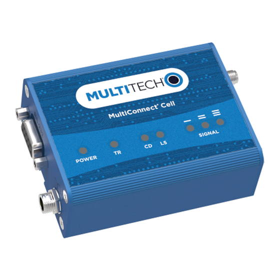
PRODUCT OVERVIEW Chapter 1 – Product Overview About the MultiConnect Cell Modem ® The MultiConnect Cell 100 Series cellular modem is a compact communications platform that provides cellular capabilities for fixed and mobile applications. It is intended for use in settings demanding reliable performance under rugged conditions, low power and long range such as remotely monitoring solar micro-inverters, power generators, tanks, pipelines, meters, pumps and valves in any energy, utility or industrial application. -
Page 7: Chapter 2 - Hardware Information
HARDWARE INFORMATION Chapter 2 – Hardware Information Dimensions ® MultiConnect Cell MTC-MNG6 User Guide... -
Page 8: Serial
HARDWARE INFORMATION Serial ® MultiConnect Cell MTC-MNG6 User Guide... -
Page 9: Mtc-Mng6 Specifications
HARDWARE INFORMATION MTC-MNG6 Specifications Category Description General Standards LTE UE Category M1 3GPP Rel. 14 Compliant 3GPP Rel. 13 eDRx 3GPP Rel. 13 extended coverage 3GPP Rel. 12 PSM Frequency Bands 4G Bands: B1, B2, B3, B4, B5, B8, B8_US, B12, B13, B18, B19, B20, B25, B26, B27, B28, 2G Bands: B2, B3, B5, B8 Speed Data Speed... - Page 10 HARDWARE INFORMATION Category Description Certifications and Compliance EMC and Radio FCC Part 15 Class B Compliance FCC Part 22H, 24E, 27, 90 CE Mark, RED (EU) UKCA Safety Compliance UL 62368-1 UL 60950-1 cUL 62368-1 60950-1 IEC 62368-1 IEC 60950-1 Network Compliance PTCRB Carrier...
-
Page 11: Descriptions Of Leds
HARDWARE INFORMATION Descriptions of LEDs The top panel contains the following LEDs: Power and Terminal Ready LEDs—The Power LED indicates that DC power is present and the TR LED indicates when the unit is ready to receive data. Modem LEDs—Two modem LEDs indicate carrier detection and link status. Signal LEDs—Three signal LEDs display the signal strength level of the wireless connection. -
Page 12: Rs-232 9-Pin Female Connector
HARDWARE INFORMATION RS-232 9-Pin Female Connector Abbreviation Description In/Out Carrier Detect Receive Transmit Data Terminal Ready Ground Data Set Ready Request to Send Clear to Send Ring Indicator ® MultiConnect Cell MTC-MNG6 User Guide... -
Page 13: Power Measurements
HARDWARE INFORMATION Power Measurements Multi-Tech Systems, Inc. recommends incorporating a 10% buffer into your power source when determining product load. Serial Model: MTC-MNG6-B01 Power Draw Radio Sleep Mode Cellular Live Average Average TX Total Inrush Total Inrush Protocol Current Connection Connection Current at Pulse... - Page 14 HARDWARE INFORMATION Radio Sleep Mode Cellular Live Average Average TX Total Inrush Total Protocol Current Connection Connection Current Pulse Charge Inrush Idle, No Data Idle Current at Max Amplitude Charge Power Current Duration During Powerup LTE 707.5 26 mA 26 mA 325 mA 828 mA 0.447 mC...
-
Page 15: Chapter 3 - Antenna And Activation Information
RF exposure. Cellular Antenna Cellular devices were approved with the following antenna: Manufacturer: Wieson Model Number: ARY118-0167-001-00 MultiTech ordering information: Model Quantity ANLTE4V2-1HRA ANLTE4V2-2HRA ANLTE4V2-10HRA ANLTE4V2-50HRA Cellular Antenna Specifications... - Page 16 ANTENNA AND ACTIVATION INFORMATION Category Description Peak Gain 619-960 MHz: 1.89 dBi 1447-2690 MHz: 3.95 dBi 3300-3800 MHz: 1.56 dBi Radiation Omni-directional Polarization Linear Connector SMA(M) ® MultiConnect Cell MTC-MNG6 User Guide...
-
Page 17: Chapter 4 - Safety Warnings
SAFETY WARNINGS Chapter 4 – Safety Warnings Radio Frequency (RF) Safety Due to the possibility of radio frequency (RF) interference, it is important that you follow any special regulations regarding the use of radio equipment. Follow the safety advice given below. Operating your device close to other electronic equipment may cause interference if the equipment is inadequately protected. -
Page 18: Notice Regarding Compliance With Fcc, Eu, And Industry Canada Requirements For Rf Exposure
SAFETY WARNINGS Notice regarding Compliance with FCC, EU, and Industry Canada Requirements for RF Exposure The antenna intended for use with this unit meets the requirements for mobile operating configurations and for fixed mounted operations, as defined in 2.1091 of the FCC rules for satisfying RF exposure compliance. This device also meets the European RF exposure requirements of EN 62311. -
Page 19: Chapter 5 - Installing And Using The Device
INSTALLING AND USING THE DEVICE Chapter 5 – Installing and Using the Device Installing a SIM Card This model requires a mini (3FF) SIM card, which is supplied by your cellular service provider. To install the SIM card: Locate the SIM card slot on the side of the modem. The slot is labeled SIM. Slide the SIM card into the SIM card slot with the contact side facing down as shown. -
Page 20: Placing Serial Devices In Power Save Mode
Use USB 3.0 ports if available. These ports are typically rated for more current. The USB cable is available through MultiTech. The part number is CA-USB-A-MINI-B-3 Mounting Device to Flat Surface Locate the groove on the bottom of the device. -
Page 21: Chapter 6 - Configuring And Communicating With Your Device
CONFIGURING AND COMMUNICATING WITH YOUR DEVICE Chapter 6 – Configuring and Communicating with Your Device Before Using the Device Before using the device: Install any drivers. Refer to the separate driver installation guide for your device. On your computer, install terminal software that can communicate with the device, such as HyperTerminal, Tera Term, Kermit, or Putty. -
Page 22: Configuring Device Firmware For Your Cellular Network
CONFIGURING AND COMMUNICATING WITH YOUR DEVICE Configuring Device Firmware for Your Cellular Network Before connecting to a cellular network, you need to configure the device for that cellular network. This step is required only the first time you use the device and if you change cellular carrier. Important: Configure the device for Cat M1 use only. -
Page 23: Registering The Device On A Cellular Network
CONFIGURING AND COMMUNICATING WITH YOUR DEVICE Registering the Device on a Cellular Network When configured with AT+COPS=0 the device automatically attempts to register with a carrier network. With the SIM and device properly configured and good reception network registration takes less than a minute. Otherwise, it may take more than 5 minutes. -
Page 24: Example
Verizon network. More information on initiating a FOTA update from the (the customer’s) local host processor (pull FOTA) is available at: https://www.multitech.com/vzw-catm1 It includes an AT command sequence example showing a possible FOTA implementation. -
Page 25: Configuring Device As Udp Listener To Accept Udp Client Connections
CONFIGURING AND COMMUNICATING WITH YOUR DEVICE where apnname is the APN your cellular provider assigned to your SIM card. Reset the radio module Enter: AT+CFUN=1,1 Bring up Data Connection Using Internal IP stack Enter: Verizon: AT#SGACT=3,1 Other Networks: AT#SGACT=1,1 The device responds with the IP Address the cellular provider assigned to the device on connection, followed by OK. - Page 26 CONFIGURING AND COMMUNICATING WITH YOUR DEVICE Enter: Should return: +CEREG: 0,1 or +CEREG: 0,5 Configure socket parameters Enter: AT#SCFG=1,3,300,240,600,50 Activate context one Enter: Verizon: AT#SGACT=3,1 Other Networks: AT#SGACT=1,1 Set firewall rule to accept connections: AT#FRWL=1,"###.##.###.#","###.##.###.#" where ###.##.###.# represents the IP range. For example: AT#FRWL=1,"204.26.122.1","204.26.122.255"...
-
Page 27: Configuring Device As Udp Client To Connect To Udp Server
CONFIGURING AND COMMUNICATING WITH YOUR DEVICE Configuring Device as UDP Client to Connect to UDP Server Configure and Connect the Device To configure the device as a UDP client: Check signal strength. Enter: AT+CSQ Verify device is registered on the cellular network. Enter: AT+CEREG? Should return:... -
Page 28: Transferring Ftp File To Ftp Server
CONFIGURING AND COMMUNICATING WITH YOUR DEVICE Transferring FTP File to FTP Server To connect to FTP server and upload files: Check signal strength. Enter: AT+CSQ Verify device is registered on the cellular network. Enter: AT+CEREG? Should return: +CEREG: 0,1 or +CEREG: 0,5 Activate context Enter: Verizon:... -
Page 29: Downloading File From Ftp Server
CONFIGURING AND COMMUNICATING WITH YOUR DEVICE NO CARRIER Close the FTP connection. Enter: AT#FTPCLOSE Close the PPP data connection. Enter: Verizon: AT#SGACT=3,0 Other Networks: AT#SGACT=1,0 The device responds with OK. Downloading File from FTP Server To connect to an FTP server and download files: Check signal strength. -
Page 30: Reading, Writing And Deleting Messages
CONFIGURING AND COMMUNICATING WITH YOUR DEVICE AT#FTPCWD="folder1" Enter the file name. Enter: AT#FTPGET="filename.txt" where filename.txt is the file to download. The device responds with: CONNECT The file is received through the device. The device responds with: NO CARRIER The data connection closes automatically when the file sending ends. Closing the FTP Data Connection After the file is sent: Close the FTP connection. -
Page 31: Sending Text Messages
CONFIGURING AND COMMUNICATING WITH YOUR DEVICE Where 0001112222 is the recipient phone number and 20161006135126 is received data in the format YYYYMMDDHHMMSS. Sending Text Messages To send a text message in text mode: Check signal strength. Enter: AT+CSQ Verify device is registered on the cellular network. Enter: AT+CEREG? Should return:... -
Page 32: Powering Down Your Device
CONFIGURING AND COMMUNICATING WITH YOUR DEVICE AT+CMGD=1,# where 1 is the index in the selected storage and # is the delflag option. Enter: Deletes message in the specified index. Deletes all read messages from selected storage. Leaves unread messages and stored device-originated messages. -
Page 33: Chapter 7 - Regulatory Information
REGULATORY INFORMATION Chapter 7 – Regulatory Information 47 CFR Part 15 Regulation Class B Devices This equipment has been tested and found to comply with the limits for a Class B digital device, pursuant to part 15 of the FCC Rules. These limits are designed to provide reasonable protection against harmful interference in a residential installation. -
Page 34: Fcc Grant Information
REGULATORY INFORMATION FCC Grant Information FCC Identifier: RI7ME910G1WW Equipment Class: PCS Licensed Transmitter Notes: ME910G1-WW LTE Module CAT M Approval: Single Modular FCC Rule Part Frequency Range Power Output Frequency Tolerance Emission (MHz) (mW) (PPM) Designator 824.2 - 848.8 1.79 2.5 PM 246KGXW 824.2 - 848.8... - Page 35 REGULATORY INFORMATION FCC Rule Part Frequency Range Power Output Frequency Tolerance Emission (MHz) (mW) (PPM) Designator 699.1 - 715.9 0.23 2.5 PM 184KG7D 699.7 - 715.3 0.22 2.5 PM 1M10G7D 699.7 - 715.3 2.5 PM 938KW7D 777.1 - 786.9 0.19 2.5 PM 129KG7D 777.1 - 786.9...
-
Page 36: Industry Canada Class B Notice
REGULATORY INFORMATION Industry Canada Class B Notice This Class B digital apparatus meets all requirements of the Canadian Interference-Causing Equipment Regulations. Cet appareil numérique de la classe B respecte toutes les exigences du Reglement Canadien sur le matériel brouilleur. This device complies with Industry Canada license-exempt RSS standard(s). The operation is permitted for the following two conditions: the device may not cause interference, and this device must accept any interference, including interference that may cause undesired operation of... -
Page 37: Emc, Safety, And Radio Equipment Regulations (Ukca)
Council Directive 2014/53/EU on radio equipment and telecommunications terminal equipment and the mutual recognition of their conformity. MultiTech declares that this device is in compliance with the essential requirements and other relevant provisions of Directive 2014/53/EU. The declaration of conformity may be downloaded at https://www.multitech.com/red... -
Page 38: Chapter 8 - Environmental Notices
Substances) complements the WEEE Directive by banning the presence of specific hazardous substances in the products at the design phase. The WEEE Directive covers all MultiTech products imported into the EU as of August 13, 2005. EU-based manufacturers, distributors, retailers and importers are obliged to finance the costs of recovery from municipal collection points, reuse, and recycling of specified percentages per the WEEE requirements. -
Page 39: Restriction Of The Use Of Hazardous Substances (Rohs)
2015/863 of the European Parliament (Restriction of the use of certain Hazardous Substances in electrical and electronic equipment - RoHS 3). These MultiTech products do not contain the following banned chemicals Lead, [Pb] < 1000 PPM Mercury, [Hg] <... -
Page 40: Chapter 9 - Using Connection Manager
Open or unzip the Connection Manager file and run the installer (.msi file). On the MultiTech Connection Manager Setup Wizard Welcome Panel, click Next. Read the end-user license agreement and check I accept the terms in the License Agreement. Click Next. -
Page 41: Setting Up A Serial Device In Windows Device Manager
In the Setup Wizard, click Finish. Note: To open Connection Manager automatically after installation, check Start the MultiTech Connection Manager when the installation is finished. If using a USB device, you can connect the device to the carrier's network with Connection Manager. Refer to Connecting a Device. - Page 42 USING CONNECTION MANAGER Select Install the hardware that I manually select from a list, then click Next. Select Modems, then click Next. Check Don't detect my modem; I will select it from a list, then click Next. Select Standard Modem Types, then select Standard 33600 bps Modem on the right. Important: Make sure that you select only Standard 33600 bps Modem.
-
Page 43: Connecting A Device
USING CONNECTION MANAGER Connecting a Device Before You Begin Make sure that your device is connected to the computer where Connection Manager is installed. If you have a serial device, set up the device in Device Manager. Refer to Setting Up a Serial Device in Windows Device Manager. -
Page 44: Uninstalling Connection Manager
The steps above describe how to uninstall Connection Manager using Control Panel. You can also uninstall the application by using the installer file (.msi). Double-click the file, in the MultiTech Connection Manager Setup Wizard, click Next, and then select Remove on the next two pages. -
Page 45: Connection Manager User Interface
USING CONNECTION MANAGER Connection Manager User Interface Connection Manager consists of the following tabs: Main Settings Connection Details Terminal Charts Main tab The Main tab displays the following: Status of device connection: Searching, Connecting, Connected, Disconnecting, or Disconnected The action button, which changes according to the current device connection status: Detect, Connect, or Disconnect Signal strength bars and percentage indicator (only when connection to the carrier's network is established) Note:... -
Page 46: Settings Tab
USING CONNECTION MANAGER Connection statistics: download and upload speeds, amount of traffic sent and received (only when connection to the carrier's network is established) The keep-alive check status and when the last ping response was received if Enable keep-alive check is checked on the Connection tab. -
Page 47: Troubleshooting
USING CONNECTION MANAGER Troubleshooting Serial COM port is not available in the Serial Modem Settings Close Connection Manager and reopen it. Device is not detected ("No Device") After following the steps to activate your device, the Main tab still indicates "No Device." Try the following steps: Click the Settings tab and make sure that the appropriate modem type is selected: USB or Serial. -
Page 48: System Cannot Connect To Serial Device
USING CONNECTION MANAGER System Cannot Connect to Serial Device If your system cannot establish a connection with a serial device, verify Connection Manager settings match modem and serial port settings on the computer. In Connection Manager, click on the Settings tab. In Device Manager, open Modems and then right-click on your device and select open the Properties. - Page 49 USING CONNECTION MANAGER In Device Manager, open Ports (COM & LPT) and then right-click on the Com Port used by your device and select Properties. Click on the Port Settings tab to confirm the Bits per second, Date bits, Parity, Stop bits and Flow control match those settings in Connection Manager.
- Page 50 USING CONNECTION MANAGER ® MultiConnect Cell MTC-MNG6 User Guide...
-
Page 51: Index
INDEX Index activation...............40 FCC certification ............34 antenna .................15 FCC Notice AT#SHDN ...............32 Class B ..............33 FOTA................24 file download ............29 file transfer ..............28 build options ..............6 server ..............28 29 FUOTA ................24 cable................12 cellular network ............23 hazardous substances ...........39 certification FCC ................34 Class B ................33 Industry Canada ............36 command mode ............21... - Page 52 INDEX SIM card ..............19 RoHS................39 RS-232 ................12 client ................24 text messages delete ...............31 read ................30 safety troubleshooting RF interference ............17 Connection Manager ..........47 send data.............24 25 27 serial cable ..............12 shutdown ..............32 signal strength verify ................23 client ..............25 27 SIM card listener ..............25 install................19 server ...............27...
Need help?
Do you have a question about the MultiConnect Cell and is the answer not in the manual?
Questions and answers