Table of Contents
Advertisement
Quick Links
Advertisement
Table of Contents

Subscribe to Our Youtube Channel
Related Manuals for Multitech MultiConnect Cell MTC-G3


Summary of Contents for Multitech MultiConnect Cell MTC-G3
- Page 1 ® MultiConnect Cell MTC-G3 User Guide...
- Page 2 Legal Notices The MultiTech products are not designed, manufactured or intended for use, and should not be used, or sold or re-sold for use, in connection with applications requiring fail-safe performance or in applications where the failure of the products would reasonably be expected to result in personal injury or death, significant property damage, or serious physical or environmental damage.
-
Page 3: Table Of Contents
CONTENTS Contents Chapter 1 – Product Overview ..........................5 About the MultiConnect Cell Modem........................... 5 Documentation ................................5 Descriptions of LEDs..............................6 Side Panels ..................................7 Specifications ................................8 RS-232 9-Pin Female Connector ..........................10 Power Draw MTC-G3 ..............................10 Dimensions.................................. - Page 4 CONTENTS Chapter 5 – Using Linux ............................21 Shell Commands................................21 Testing Serial Ports..............................21 Create a PPP Connection ............................21 H5 Example ................................21 EV3 Example................................22 MAT1 (MVW1) Example............................22 Chapter 6 – Configuring and Communicating with Your Device................24 Interacting with Your Device Overview ........................
-
Page 5: Chapter 1 - Product Overview
They are available with RS- 232 or USB connectors. Serial Documentation The following documentation is available on the Multi-Tech Installation Resources website at www.multitech.com/setup/product.go. Document Description MultiConnect Cell User Guide This document. Provides an overview, safety and regulatory information, schematics, and general device information. -
Page 6: Descriptions Of Leds
PRODUCT OVERVIEW Descriptions of LEDs The top panel contains the following LEDs: Power and Terminal Ready LEDs—The Power LED indicates that DC power is present and the TR LED indicates when the unit is ready to receive data. Modem LEDs—Two modem LEDs indicate carrier detection and link status. Signal LEDs—Three signal LEDs display the signal strength level of the wireless connection. -
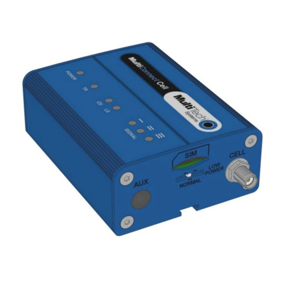
Page 7: Side Panels
PRODUCT OVERVIEW Side Panels The device has connectors on either side. The figures that follow show the side panels. Serial Note: The power-saving switch—which appears with the NORMAL and LOW POWER labels—is included only on models that have a serial connector. ®... -
Page 8: Specifications
PRODUCT OVERVIEW Specifications Category Description General Performance GPRS Class 10 Frequency Bands Quad-band EGSM 850/900/1800/1900 MHz Speed Packet Data Up to 85.6 Kbps downlink and uplink Point-to-Point Messaging Mobile-Terminated SMS Mobile-Originated SMS Connectors Cellular Female SMA RS-232 Mini-B, USB 2.0 high speed or better Power 2.5 mm miniature screw-on, RS-232 models Power Requirements... - Page 9 PRODUCT OVERVIEW Category Description Safety Compliance UL 60950-1 IEC 60950-1 ANSI/ISA 12.12.01 2013 and CSA C22.2 No. 213 EN 60079-0:2012+A11:2013 EN 60079-15:2010 Warranty Two years Optional power must be UL Listed ITE power supply marked LPS or Class 2 rated 7 to 32 V dc, 0.5 A . Certification does not apply or extend to voltages outside certified range, and has not been evaluated by UL for operating voltages beyond tested range.
-
Page 10: Rs-232 9-Pin Female Connector
PRODUCT OVERVIEW RS-232 9-Pin Female Connector Abbreviation Description In/Out Carrier Detect Receive Transmit Data Terminal Ready Ground Data Set Ready Request to Send Clear to Send Ring Indicator Power Draw MTC-G3 5 volts Cellular call box Average measured TX Pulse (AVG) Total inrush charge connection no data current (amps) at... -
Page 11: Dimensions
PRODUCT OVERVIEW Dimensions Serial ® MultiConnect Cell MTC-G3 User Guide... -
Page 12: Usb
PRODUCT OVERVIEW ® MultiConnect Cell MTC-G3 User Guide... -
Page 13: Installing A Sim Card
PRODUCT OVERVIEW Installing a SIM Card This model requires a SIM card, which is supplied by your service provider. To install the SIM card: Locate the SIM card slot on the side of the modem. The slot is labeled SIM. Slide the SIM card into the SIM card slot with the contact side facing down as shown. -
Page 14: Chapter 2 - Safety Warnings
SAFETY WARNINGS Chapter 2 – Safety Warnings Radio Frequency (RF) Safety Due to the possibility of radio frequency (RF) interference, it is important that you follow any special regulations regarding the use of radio equipment. Follow the safety advice given below. Operating your device close to other electronic equipment may cause interference if the equipment is inadequately protected. -
Page 15: Hazardous Locations Warnings
SAFETY WARNINGS Hazardous Locations Warnings Class I, Division 2, Groups A, B, C, and D Hazardous Locations (US and Canada) ANSI_ISA_12.12.01_2013 and CSA C22.2 No. 213 -HZ models only The MTC modem is a OPEN-TYPE device and is intended for installation into a IP54 style enclosure. The enclosure would only allow access to the modem via a key or tool. -
Page 16: Antenna
SAFETY WARNINGS The device is intended to be powered by a Certified SELV non-energy hazardous power supply. Antenna The antenna intended for use with this unit meets the requirements for mobile operating configurations and for fixed mounted operations, as defined in 2.1091 and 1.1307 of the FCC rules for satisfying RF exposure compliance. If an alternate antenna is used, consult user documentation for required antenna specifications. -
Page 17: Chapter 3 - Installing And Using The Device
INSTALLING AND USING THE DEVICE Chapter 3 – Installing and Using the Device Installing the Device Connect a suitable antenna to the antenna connector. If your device is the serial version: Connect the DE9 male connector (9-pin) of the RS-232 cable to the RS-232 connector on the device, then connect the other end to the serial port on the other desired device. -
Page 18: Usb Cable Recommendations
If possible, use a USB port that connects directly to the motherboard rather than a USB port with added cabling inside the computer chassis. Use USB 3.0 ports if available. These ports are typically rated for more current. You can order the USB cable through MultiTech. The part number is CA-USB-A-MINI-B-3 Powering Down Your Device CAUTION: Failing to properly power down the device before removing power may corrupt your device's file system. -
Page 19: Chapter 4 - Antenna And Activation Information
Account Activation for Cellular Devices Some MultiTech devices are pre-configured to operate on a specific cellular network. To use the device, you must set up a cellular data account with your service provider. Each service provider has its own process for adding devices to their network. -
Page 20: Device Phone Number
ANTENNA AND ACTIVATION INFORMATION Device Phone Number Every device has a unique phone number. Your service provider supplies a phone number when you activate your account, or if your device has a SIM card, the phone number may be on it. Wireless service provider implementation may vary. -
Page 21: Chapter 5 - Using Linux
USING LINUX Chapter 5 – Using Linux Shell Commands Testing Serial Ports To test the serial ports created by the driver, type in a shell: Note: Sending ATE0 is required, to avoid issues in the terminal output. It prevents the sending/receiving spurious characters to/from the modem when used with the Linux commands “echo”... -
Page 22: Ev3 Example
USING LINUX EV3 Example Step 1. Use a text editor to create a peer file containing the lines in the example below. (/dev/ttyUSB2 may need to be something like /dev/ttyS0 for a serial build). Save the file as /etc/ppp/peers/EV3-peer. Example peer file: /dev/ttyUSB2 connect "/usr/sbin/chat -v -f /etc/chatscripts/EV3-chat"... - Page 23 USING LINUX Step 2. Use a text editor to create a chat script containing the lines in the example below. In this example [APN] should be replaced with the APN assigned by your cellular provider. Save the file as /etc/chatscripts/MAT1-chat. Example chat script: ABORT "ERROR"...
-
Page 24: Chapter 6 - Configuring And Communicating With Your Device
CONFIGURING AND COMMUNICATING WITH YOUR DEVICE Chapter 6 – Configuring and Communicating with Your Device Interacting with Your Device Overview This section describes how to use AT commands to interact with your device. Using terminal software such as Kermit, you can issue AT commands to communicate with and configure your modem. The AT commands let you establish, read and modify device parameters and help you control how the device operates. -
Page 25: Verifying Signal Strength
CONFIGURING AND COMMUNICATING WITH YOUR DEVICE Stop bit: 1 Flow control: hardware To confirm communication with the device: Type AT and press Enter. If the device responds with OK, it is properly communicating. Verifying Signal Strength To verify the device signal strength, enter: AT+CSQ The command indicates signal quality, in the form: +CSQ: <rssi>,<ber>... -
Page 26: Example
CONFIGURING AND COMMUNICATING WITH YOUR DEVICE Example A example response to AT+CSQ: +CSQ: 15,1 Checking Network Registration Before establishing a packet data connection, verify the is device registered on the network. To do this enter the network registration report read command: AT+CREG? If the device returns: +CREG: 0,1... -
Page 27: Configuring Device As Udp Listener To Accept Udp Client Connections
CONFIGURING AND COMMUNICATING WITH YOUR DEVICE To close Socket 1, enter: AT#SH=1 The device responds with OK. To close the data connection: Enter: AT#SGACT=1,0 The device responds with OK. Configuring Device as UDP Listener to Accept UDP Client Connections To configure the device as a UDP client: Check signal strength. -
Page 28: Configuring Device As Udp Client To Connect To Udp Server
CONFIGURING AND COMMUNICATING WITH YOUR DEVICE CONNECT You can send and receive data. Exit Data Mode and Close Connection To exit data mode and close the socket: Enter the escape sequence: To close Socket 1, enter: AT#SH=1 The device responds with OK. To close the data connection, enter: AT#SGACT=1,0 The device responds with OK. -
Page 29: Configuring Device As Udp Listener To Accept Udp Client Connections
CONFIGURING AND COMMUNICATING WITH YOUR DEVICE Exit Data Mode and Close Connection To exit data mode and close the socket: Enter the escape sequence: To close Socket 1, enter: AT#SH=1 The device responds with OK. To close the data connection, enter: AT#SGACT=1,0 The device responds with OK. -
Page 30: Transferring Ftp File To Ftp Server
CONFIGURING AND COMMUNICATING WITH YOUR DEVICE Accept incoming connection ID 1 Enter: AT#SA=1 The device indicates a client successfully established a listener connection. CONNECT You can send and receive data. Exit Data Mode and Close Connection To exit data mode and close the socket: Enter the escape sequence: To close Socket 1, enter: AT#SH=1... -
Page 31: Downloading File From Ftp Server
CONFIGURING AND COMMUNICATING WITH YOUR DEVICE Configure file transfer type. Enter: AT#FTPTYPE=# where # is 0 for binary or 1 for ASCII. Enter the file name to be sent to the FTP server and initiate connection. Enter: AT#FTPPUT="file.txt" The device responds with: CONNECT Send the file through the device. -
Page 32: Reading, Writing And Deleting Messages
CONFIGURING AND COMMUNICATING WITH YOUR DEVICE Set FTP operations timeout to 10 seconds Enter: AT#FTPTO=1000 Configure FTP server IP address with username and password. Enter: AT#FTPOPEN="###.##.###.#","username","password",0 where ###.##.###.# is the IP address and the username and password for the FTP server. Configure file transfer type. -
Page 33: Writing Text Messages
CONFIGURING AND COMMUNICATING WITH YOUR DEVICE Enter: AT+CMGR=1 Example response: +CMGR: "REC UNREAD","+10001112222z`z","","13/09/05,13:39:40-20" How are you? Where 0001112222 is the phone number. Writing Text Messages To send a text message in text mode: Put the device in text mode. Enter: AT+CMGF=1 The device responds. - Page 34 CONFIGURING AND COMMUNICATING WITH YOUR DEVICE Deletes all read messages. Leaves unread messages and stored device- originated messages. Deletes all read and sent device-originated messages. Leaves unread messages and unsent device-originated messages. Deletes all read messages and sent and unsent device-orginated messages. Leaves unread messages.
-
Page 35: Chapter 7 - Regulatory Information
2011/65/EU of the European Parliament (Restriction of the use of certain Hazardous Substances in electrical and electronic equipment - RoHS). These MultiTech products do not contain the following banned chemicals Lead, [Pb] < 1000 PPM Mercury, [Hg] <... -
Page 36: Reach Statement
Substances) complements the WEEE Directive by banning the presence of specific hazardous substances in the products at the design phase. The WEEE Directive covers all MultiTech products imported into the EU as of August 13, 2005. EU-based manufacturers, distributors, retailers and importers are obliged to finance the costs of recovery from municipal collection points, reuse, and recycling of specified percentages per the WEEE requirements. - Page 37 REGULATORY INFORMATION ® MultiConnect Cell MTC-G3 User Guide...
-
Page 38: Information On Hs/Ts Substances According To Chinese Standards
REGULATORY INFORMATION Information on HS/TS Substances According to Chinese Standards In accordance with China's Administrative Measures on the Control of Pollution Caused by Electronic Information Products (EIP) # 39, also known as China RoHS, the following information is provided regarding the names and concentration levels of Toxic Substances (TS) or Hazardous Substances (HS) which may be contained in Multi-Tech Systems Inc. -
Page 39: Information On Hs/Ts Substances According To Chinese Standards (In Chinese)
REGULATORY INFORMATION Information on HS/TS Substances According to Chinese Standards (in Chinese) 依 依 照 照 中 中 国 国 标 标 准 准 的 的 有 有 毒 毒 有 有 害 害 物 物 质 质 信 信 息 息 根据中华人民共和国信息产业部...
Need help?
Do you have a question about the MultiConnect Cell MTC-G3 and is the answer not in the manual?
Questions and answers