Table of Contents
Advertisement
Quick Links
Advertisement
Table of Contents

Related Manuals for Multitech MultiConnect microCell


Summary of Contents for Multitech MultiConnect microCell
- Page 1 ® MultiConnect microCell MTCM-LAT3 and -LSP3 User Guide...
- Page 2 Legal Notices The MultiTech products are not designed, manufactured or intended for use, and should not be used, or sold or re-sold for use, in connection with applications requiring fail-safe performance or in applications where the failure of the products would reasonably be expected to result in personal injury or death, significant property damage, or serious physical or environmental damage.
-
Page 3: Table Of Contents
CONTENTS Contents Chapter 1 – Product Overview ..........................5 About the MultiConnect microCell Modem ......................... 5 Dimensions..................................6 LED Descriptions ................................7 MTCM-LAT3 Specifications ............................8 MTCM-LSP3 Specifications............................10 Power Measurements..............................11 MTCM-LAT3 Power Draw............................11 MTCM-LSP3 Power Draw ............................11 Chapter 2 –... - Page 4 CONTENTS Configuring Device as UDP Client to Connect to UDP Server ................... 22 Transferring FTP File to FTP Server ........................... 23 Downloading File from FTP Server..........................24 Reading, Writing and Deleting Messages ........................26 Sending Text Messages ............................. 26 Reading Text Messages............................. 26 Deleting Messages ..............................
-
Page 5: Chapter 1 - Product Overview
Chapter 1 – Product Overview About the MultiConnect microCell Modem The MultiConnect microCell is a compact and simple communications platform that provides cellular capabilities for fixed and mobile applications. It is intended for use in settings such as vending, smart parking, medical, smart inventory tracking equipment and commercial applications. -
Page 6: Dimensions
PRODUCT OVERVIEW Dimensions ® MultiConnect microCell MTCM-LAT3 and -LSP3 User Guide... -
Page 7: Led Descriptions
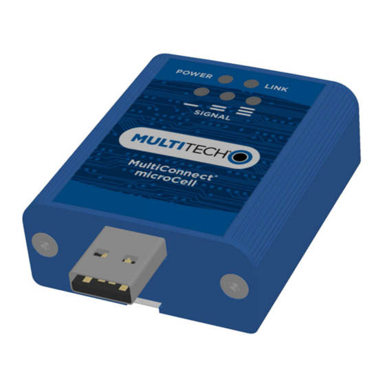
PRODUCT OVERVIEW LED Descriptions The top panel contains the following LEDs: Power LED—The Power LED indicates that DC power is present. Link LED—The Link LED indicated that it is registered on the network. Signal LEDs—Three signal LEDs can display the signal strength level of the wireless connection. LED Indicators POWER Indicates presence of DC power when lit. -
Page 8: Mtcm-Lat3 Specifications
PRODUCT OVERVIEW MTCM-LAT3 Specifications Category Description General Standards LTE 3GPP Release 9 HSPA+ 21/GPRS fallback USB Interface is CDC-ACM compliant TCP/IP Functions FTP, SMTP, SSL, TCP, UDP Frequency Bands 4G: 700 (B12/B13)/850 (B5)/AWS 1700 (B4)/1900 (B2) 3G: 850 (B5)/1900 (B2) Speed Data Speed LTE: 10 Mbps downlink/5 Mbps uplink... - Page 9 PRODUCT OVERVIEW Category Description Radio Compliance FCC Part 22, 24, 27 Safety Compliance UL 60950-1 2nd ED cUL 60950-1 2nd ED IEC 60950-1 2nd ED Network Compliance PTCRB Carrier AT&T ® MultiConnect microCell MTCM-LAT3 and -LSP3 User Guide...
-
Page 10: Mtcm-Lsp3 Specifications
PRODUCT OVERVIEW MTCM-LSP3 Specifications Category Description General Standards LTE 3GPP Release 9 HSPA+ 21/GPRS fallback USB Interface is CDC-ACM compliant TCP/IP Functions FTP, SMTP, SSL, TCP, UDP Frequency Bands 4G: 700 (B12/B26)/850 (B5)/AWS 1700 (B4)/1900 (B2) 3G: 850 (B5)/1900 (B2) Speed Data Speed LTE: 10 Mbps downlink/5 Mbps uplink... -
Page 11: Power Measurements
PRODUCT OVERVIEW Category Description Radio Compliance FCC Part 22, 24, 27 Safety Compliance UL 60950-1 2nd ED cUL 60950-1 2nd ED IEC 60950-1 2nd ED Network Compliance PTCRB Carrier Sprint Power Measurements Multi-Tech Systems, Inc. recommends incorporating a 10% buffer into your power source when determining product load. - Page 12 PRODUCT OVERVIEW Maximum Power: The continuous current during maximum data rate with the radio transmitter at maximum power. TX Pulse: The average peak current during a GSM850 transmission burst period or HSDPA/LTE connection. The transmission burst duration for GSM850 can vary, depending on what transmission scheme is being deployed (GPRS Class 8, Class 10, GSM, etc.).
-
Page 13: Chapter 2 - Safety Warnings
SAFETY WARNINGS Chapter 2 – Safety Warnings Radio Frequency (RF) Safety Due to the possibility of radio frequency (RF) interference, it is important that you follow any special regulations regarding the use of radio equipment. Follow the safety advice given below. Operating your device close to other electronic equipment may cause interference if the equipment is inadequately protected. -
Page 14: Chapter 3 - Installing And Using The Device
INSTALLING AND USING THE DEVICE Chapter 3 – Installing and Using the Device Installing the Device Important: Install drivers on your computer before connecting the device. Connect antennas to the antenna connectors. Connect the USB connector to your computer or other USB high power device, such as a hub. The POWER LED lights after the device powers up. -
Page 15: Removing A Sim Card
INSTALLING AND USING THE DEVICE Removing a SIM Card To remove the SIM card, push the SIM card in. The device ejects the SIM card. Mounting Device to Flat Surface Locate the groove on the bottom of the device. Slide the mounting bracket through the groove. To secure the bracket to the desired surface, place and tighten two screws in the holes on either end of the mounting bracket. -
Page 16: Chapter 4 - Antenna And Activation Information
ANTENNA AND ACTIVATION INFORMATION Chapter 4 – Antenna and Activation Information Notice regarding Compliance with FCC, EU, and Industry Canada Requirements for RF Exposure The antenna intended for use with this unit meets the requirements for mobile operating configurations and for fixed mounted operations, as defined in 2.1091 of the FCC rules for satisfying RF exposure compliance. -
Page 17: Device Phone Number
All applications interacting with Sprint approved MultiTech devices must be written in a manner where they do not interfere/interrupt the Sprint Hands-Free Activation (HFA) process or OMA-DM processes. If the MultiTech device will be co-located with any other transmitters you will be required to submit your device to an FCC approved lab for additional testing. -
Page 18: Chapter 5 - Configuring And Communicating With Your Device
CONFIGURING AND COMMUNICATING WITH YOUR DEVICE Chapter 5 – Configuring and Communicating with Your Device Before Using the Device Before using the device: Install any drivers. Refer to the separate driver installation guide for your device. Power up your device and ensure it is connected to your computer that issues AT commands. Note: Wait 10 seconds after power-up before issuing any AT commands. -
Page 19: Example
CONFIGURING AND COMMUNICATING WITH YOUR DEVICE +CSQ: <rssi>,<sq> Where: <rssi> Received signal strength indication. (-113) dBm or less (-111) dBm 2-30 (-109) dBm - (-53) dBm / 2 dBm per step (-51) dBm or greater Not known or not detectable <sq>... -
Page 20: Sending And Receiving Data
CONFIGURING AND COMMUNICATING WITH YOUR DEVICE +CEREG: 0,5 The device is registered. If the device returns: +CEREG: 0,2 The device is in a network searching state. If the device returns: +CEREG: 0,3 The registration is denied. If the device returns: +CEREG: 0,0 The device is not currently attempting to register to a network. -
Page 21: Configuring Device As Udp Listener To Accept Udp Client Connections
CONFIGURING AND COMMUNICATING WITH YOUR DEVICE To close Socket 1, enter: AT#SH=1 To close the data connection: Enter: Verizon: AT#SGACT=3,0 Other Networks: AT#SGACT=1,0 The device responds with OK. Configuring Device as UDP Listener to Accept UDP Client Connections To configure the device as a UDP client: Check signal strength. -
Page 22: Configuring Device As Udp Client To Connect To Udp Server
CONFIGURING AND COMMUNICATING WITH YOUR DEVICE Accept incoming connection ID 1 Enter: AT#SA=1 The device indicates a client successfully established a listener connection. CONNECT The device can send and receive data now. Exit Data Mode and Close Connection To exit data mode and close the socket: Enter the escape sequence: To close Socket 1, enter: AT#SH=1... -
Page 23: Transferring Ftp File To Ftp Server
CONFIGURING AND COMMUNICATING WITH YOUR DEVICE Enter: AT#SD=1,1,####,"###.##.###.##" where #### is the server port and ###.##.###.## is the IP number. The device responds with OK, which indicates a successful connection for sending and receiving data through the socket connection. Exit Data Mode and Close Connection To exit data mode and close the socket: Enter the escape sequence: To close Socket 1, enter:... -
Page 24: Downloading File From Ftp Server
CONFIGURING AND COMMUNICATING WITH YOUR DEVICE where ###.##.###.# is the IP address and the username and password for the FTP server. Configure file transfer type. Enter: AT#FTPTYPE=# where # is 0 for binary or 1 for ASCII. Enter the file name to be sent to the FTP server and initiate connection. Enter: AT#FTPPUT="file.txt"... - Page 25 CONFIGURING AND COMMUNICATING WITH YOUR DEVICE Enter: Verizon: AT#SGACT=3,1 Other Networks: AT#SGACT=1,1 Set FTP operations timeout to 10 seconds Enter: AT#FTPTO=100 Configure FTP server IP address with username and password. Enter: AT#FTPOPEN="###.##.###.#","username","password",0 where ###.##.###.# is the IP address and the username and password for the FTP server. Configure file transfer type.
-
Page 26: Reading, Writing And Deleting Messages
CONFIGURING AND COMMUNICATING WITH YOUR DEVICE Reading, Writing and Deleting Messages Sending Text Messages To send a text message in text mode: Check signal strength. Enter: AT+CSQ Verify device is registered on the cellular network. Enter: AT+CEREG? Should return: +CEREG: 0,1 or +CEREG: 0,5 Put the device in text mode. -
Page 27: Deleting Messages
CONFIGURING AND COMMUNICATING WITH YOUR DEVICE To read a text message in text mode: Send a message to the phone number of the currently installed SIM. Put the device in text mode. Enter: AT+CMGF=1 Read message. Enter: AT+CMGR=1 Example response: +CMGR: "REC UNREAD","0001112222","","20161006135126"... -
Page 28: Chapter 6 - Regulatory Information
REGULATORY INFORMATION Chapter 6 – Regulatory Information Industry Canada Class B Notice This Class B digital apparatus meets all requirements of the Canadian Interference-Causing Equipment Regulations. Cet appareil numérique de la classe B respecte toutes les exigences du Reglement Canadien sur le matériel brouilleur. -
Page 29: Restriction Of The Use Of Hazardous Substances (Rohs)
2015/863 of the European Parliament (Restriction of the use of certain Hazardous Substances in electrical and electronic equipment - RoHS 3). These MultiTech products do not contain the following banned chemicals Lead, [Pb] < 1000 PPM Mercury, [Hg] <... -
Page 30: Information On Hs/Ts Substances According To Chinese Standards
REGULATORY INFORMATION Information on HS/TS Substances According to Chinese Standards In accordance with China's Administrative Measures on the Control of Pollution Caused by Electronic Information Products (EIP) # 39, also known as China RoHS, the following information is provided regarding the names and concentration levels of Toxic Substances (TS) or Hazardous Substances (HS) which may be contained in Multi-Tech Systems Inc. -
Page 31: Information On Hs/Ts Substances According To Chinese Standards (In Chinese)
REGULATORY INFORMATION Information on HS/TS Substances According to Chinese Standards (in Chinese) 依 依 照 照 中 中 国 国 标 标 准 准 的 的 有 有 毒 毒 有 有 害 害 物 物 质 质 信 信 息 息 根据中华人民共和国信息产业部... -
Page 32: Chapter 7 - Using Connection Manager
Click Connection Manager. Open or unzip the Connection Manager file and run the installer (.msi file). In the MultiTech Connection Manager Setup Wizard, read the end-user license agreement and check I accept the terms in the License Agreement. Click Next to have the installer automatically disable the native WWAN AutoConfig service in Windows. -
Page 33: Setting Up A Serial Device In Windows Device Manager
To specify a folder for Connection Manager, use the default folder or click Change to browse to the folder you want to use. Click Install. A separate wizard opens for installing Telit drivers. Some MultiTech devices use embedded modules from Telit Wireless Solutions to provide cellular connectivity; these devices require Telit drivers. Select Complete setup type. - Page 34 USING CONNECTION MANAGER In the Add Hardware Wizard: Click Next. Select Install the hardware that I manually select from a list, then click Next. Select Modems, then click Next. Check Don't detect my modem; I will select it from a list, then click Next. Select Standard Modem Types, then select Standard 33600 bps Modem on the right.
-
Page 35: Connecting A Device
USING CONNECTION MANAGER Connecting a Device Before You Begin Make sure that your device is connected to the computer where Connection Manager is installed. Set up the device in Device Manager. Refer to Setting Up a Serial Device in Windows Device Manager. -
Page 36: Uninstalling Connection Manager
The steps above describe how to uninstall Connection Manager using Control Panel. You can also uninstall the application by using the installer file (.msi). Double-click the file, in the MultiTech Connection Manager Setup Wizard, click Next, and then select Remove on the next two pages. -
Page 37: Connection Manager User Interface
USING CONNECTION MANAGER Connection Manager User Interface Connection Manager consists of the following tabs: Main Settings Connection Details Terminal Charts Main tab The Main tab displays the following: Status of device connection: Searching, Connecting, Connected, Disconnecting, or Disconnected The action button, which changes according to the current device connection status: Detect, Connect, or Disconnect Signal strength bars and percentage indicator (only when connection to the carrier's network is established) Note:... -
Page 38: Settings Tab
USING CONNECTION MANAGER Connection statistics: download and upload speeds, amount of traffic sent and received (only when connection to the carrier's network is established) The keep-alive check status and when the last ping response was received if Enable keep-alive check is checked on the Connection tab. -
Page 39: Troubleshooting
USING CONNECTION MANAGER Troubleshooting Serial COM port is not available in the Serial Modem Settings Close Connection Manager and reopen it. Device is not detected ("No Device") After following the steps to activate your device, the Main tab still indicates "No Device." Try the following steps: Click the Settings tab and make sure that the appropriate modem type is selected: USB or Serial.
Need help?
Do you have a question about the MultiConnect microCell and is the answer not in the manual?
Questions and answers