Master Chef S480 Assembly Manual
Hide thumbs
Also See for S480:
- Care manual (11 pages) ,
- Assembly manual (17 pages) ,
- Assembly manual (18 pages)
Advertisement
Table of Contents
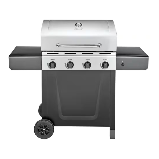
S480 Barbecue
Assembly Manual
85-3024-4 (G43208) Propane
85-3025-2 (G43209) Natural Gas
1 YeAr liMited WArrAntY
reAd And sAve MAnuAl for future reference.
if pre-assembled, leave this manual with unit for
consumer's future reference.
for product inquiries, parts, warranty and
troubleshooting support, please call 1-877-707-5463.
Manual Revision #: 13102009 PD
Advertisement
Table of Contents

Related Manuals for Master Chef S480


Summary of Contents for Master Chef S480
- Page 1 S480 Barbecue Assembly Manual 85-3024-4 (G43208) Propane 85-3025-2 (G43209) Natural Gas 1 YeAr liMited WArrAntY reAd And sAve MAnuAl for future reference. if pre-assembled, leave this manual with unit for consumer’s future reference. for product inquiries, parts, warranty and troubleshooting support, please call 1-877-707-5463.
-
Page 2: Hardware Pack
HARDWARE PACK tools needed for AsseMBlY KeY # descriPtion PArt nuMBer QuAntitY 1/4”-20UNCX13mm screw 20120-13013-036 • #2 Phillips screwdriver (long and short) 1/4”-20UNCX38mm screw 20120-13038-036 1/4”-20UNC nut 31220-13000-036 • ¼” Slotted screwdriver (long and short) NO.8 x10mm screw 20132-08010-250 • Adjustable wrench #8X3/8”... - Page 3 PARts List (PRoPANE) foR 85-3024-4 (G43208) EXPLoDED DiAGRAM (PRoPANE) foR 85-3024-4 (G43208) KeY # QuAntitY descriPtion PArt no. Top lid assembly G432-0027-01 Thermometer and bezel G451-0008-01 Logo Plate G451-0001-01 Lid handle brackets G432-0030-01 Top lid handle G432-0029-01 Lid bumpers- back G303-0038-01 Lid bumbers-Front G430-00B8-01...
- Page 4 PARts List (NAtuRAL GAs) foR 85-3025-2 (G43209) EXPLoDED DiAGRAM (NAtuRAL GAs) foR 85-3025-2 (G43209) KeY # QuAntitY descriPtion PArt no. Top lid assembly G432-0027-01 Thermometer and bezel G451-0008-01 Logo Plate G451-0001-01 Lid handle brackets G432-0030-01 Top lid handle G432-0029-01 Lid bumpers- back G303-0038-01 Lid bumbers-Front G430-00B8-01...
-
Page 5: You Will Need
AssEMBLY iNstRuCtioNs AssEMBLY iNstRuCtioNs ProPAne Model onlY Note: turn Cart assembly upside down. a. Place wheel (DF) and wheel spacer (#7) onto Note: You will need two people for this step. wheel axle (DH). “Cone” side of wheel should be against cart side panel, figure B. Assemble the tank exclusion (DC) to the left and right cart side panels (DB, DA), as shown. - Page 6 AssEMBLY iNstRuCtioNs AssEMBLY iNstRuCtioNs riGHt side sHelf AsseMBlY Note: stand cart assembly upright. tWo PEoPLE required for this step. Ensure that the a. Insert the right side shelf assembly hooks (EA regulator hose (CE) (Propane models only) is & EB) into the grooves located on the right hanging outside of cart.
-
Page 7: Side Burner Assembly
AssEMBLY iNstRuCtioNs AssEMBLY iNstRuCtioNs left side sHelf AsseMBlY side Burner AsseMBlY a. Insert the left side shelf assembly hooks (EC a. two people required in this step. Insert the and ED) into the grooves located on the left side burner valve stem (CD) through the rear of side of the burner box assembly (BA). - Page 8 AssEMBLY iNstRuCtioNs AssEMBLY iNstRuCtioNs a. Position the side burner (EF) through the a. Use the side burner venturi clip (#9) to connect opening in the side burner drip pan (EE). Make the side burner (EF) to the side burner valve sure the side burner (EF) engages the side (CD).
- Page 9 AssEMBLY iNstRuCtioNs AssEMBLY iNstRuCtioNs Place the flame tamers (BE) into the burner box. To assemble the warming rack (BG), insert the Stationary Wire stationary wire into the holes on the sides of Pivot Legs the lid. Insert warming rack pivot legs into the holes on the inside of the burner box assembly, as shown.
- Page 10 AssEMBLY iNstRuCtioNs AssEMBLY iNstRuCtioNs ProPAne Model sHoWn Electronic ignition battery not included. Unscrew the electronic ignition button (CH2) and AttENtioN: LP Cylinder is sold separately. insert one AA battery into the electronic ignition use only LP tanks that are equipped with an battery compartment (CH1), with the positive end facing outward.
Need help?
Do you have a question about the S480 and is the answer not in the manual?
Questions and answers