Advertisement
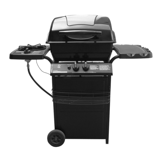
S280 Barbecue
Assembly Manual
85-3002-6 (G20717) Propane
1 YeAr liMited WArrAntY
reAd And sAve MAnuAl for future reference.
if pre-assembled, leave this manual with unit for
consumer's future reference.
for product inquiries, parts, warranty and
troubleshooting support, please call 1-877-707-5463.
Revision #: 15102009 PD
Advertisement
Table of Contents

Subscribe to Our Youtube Channel
Related Manuals for Master Chef S280


Summary of Contents for Master Chef S280
- Page 1 S280 Barbecue Assembly Manual 85-3002-6 (G20717) Propane 1 YeAr liMited WArrAntY reAd And sAve MAnuAl for future reference. if pre-assembled, leave this manual with unit for consumer’s future reference. for product inquiries, parts, warranty and troubleshooting support, please call 1-877-707-5463.
-
Page 2: Hardware Pack
HARDWARE PACK KeY # description pArt nuMBer QuAntitY tools needed for AsseMBlY 1/4”-20UNC X35 Screw 20120-13035-036 1/4”-20UNC X13 Screw 20120-13013-036 • #2 Phillips screwdriver (long and short) 1/4”-20UNC NUT 31220-13000-036 • ¼” Slotted screwdriver (long and short) Bolt (for wheel) G207-0035-9084 Washer (for wheel) G301-0028-9084... - Page 3 PARts List (PRoPANE) foR 85-3002-6 (G20717) EXPLoDED DiAGRAM (PRoPANE) foR 85-3002-6 (G20717) KeY # QuAntitY description pArt no. Top lid assembly G208-0001-01 Top lid handle G305-0090-01 Upper hinge G206-0002-A1 Burner box assembly G205-0010-02 Lower hinge G206-0010-A1 Cooking grate G206-0006-01 Flame tamer G210-0003-01 Burner G207-2400-01...
-
Page 4: Assembly Instructions
AssEMBLY iNstRUCtioNs AssEMBLY iNstRUCtioNs tWo people reQuired for All c. Assemble the wheels (DI) to the left cart legs AsseMBlY steps. (DA) and bottom brace (DH), as shown. a. Front Cart Assembly: assemble the front panel (DL) to two cart legs (DA) as shown. YOU WILL NEED: YOU WILL NEED: b. -
Page 5: You Will Need
AssEMBLY iNstRUCtioNs AssEMBLY iNstRUCtioNs a. Hook the curved end of the tank exclusion a. Position the valve assembly (CD) through the (DG) into the clip located on the back of the back of the control panel (CA), and assemble. front panel (DL). YOU WILL NEED: b. -
Page 6: Side Shelf Assembly
AssEMBLY iNstRUCtioNs AssEMBLY iNstRUCtioNs side sHelf AsseMBlY e. Position the side burner (ED) through the opening in the side burner drip pan (EC). Make a. Assemble the right side shelf (EA) to the right sure the side burner (ED) engages the side cart legs (DA), as shown. - Page 7 AssEMBLY iNstRUCtioNs AssEMBLY iNstRUCtioNs Assemble the burner (BE) into the burner box as- Burner Box AsseMBlY sembly (BA), with the burner venturi tubes facing a. Assemble the lower hinge (BB) x 2 on the back forward. of the burner box assembly (BA), as shown. YOU WILL NEED: YOU WILL NEED: b.
- Page 8 AssEMBLY iNstRUCtioNs AssEMBLY iNstRUCtioNs Assemble the heat shield (BG) to the inside of the Assemble the upper hinge (AC x2) to the top lid left burner box support (DC), as shown. assembly (AA). YOU WILL NEED: YOU WILL NEED: cAution: sHArp edGes, WeAr sAfetY Gloves durinG AsseMBlY Assemble the top lid handle (AB) to the top lid...
- Page 9 AssEMBLY iNstRUCtioNs AssEMBLY iNstRUCtioNs Position the flame tamer (BD) into the burner To assemble the warming rack (CF) insert the box assembly (BA). Note: the flame tamer (BD) stationary wire into the holes on the sides of the should be placed on to the hardware assembled lid.
- Page 10 AssEMBLY iNstRUCtioNs Hook the grease cup hook (DD) to the bottom of the burner box assembly (BA), as shown. Place the grease cup (DE) into the grease cup hook (DD).
Need help?
Do you have a question about the S280 and is the answer not in the manual?
Questions and answers