Advertisement
Quick Links
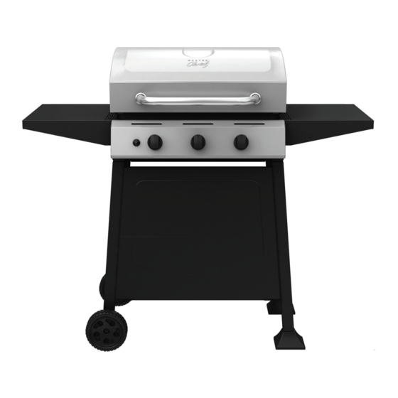
S380 Barbecue
Assembly Manual
199-9558-8 (G31216) Propane
1 YEAR LIMITED WARRANTY
READ AND SAVE MANUAL FOR FUTURE REFERENCE.
If pre-assembled, leave this manual with unit for
consumer's future reference.
For product inquiries, parts, warranty and
troubleshooting support, please call 1-855-453-2150.
Manual Revision #: 11212013 PD
ANS Z21.58b-2012-CSA 1.6b-2012
ANS Z21.58b-2012-CSA 1.6b-2012
ANS Z21.58b-2012-CSA 1.6b-2012
Advertisement

Subscribe to Our Youtube Channel
Related Manuals for Master Chef S380


Summary of Contents for Master Chef S380
- Page 1 S380 Barbecue Assembly Manual 199-9558-8 (G31216) Propane 1 YEAR LIMITED WARRANTY READ AND SAVE MANUAL FOR FUTURE REFERENCE. If pre-assembled, leave this manual with unit for consumer’s future reference. For product inquiries, parts, warranty and troubleshooting support, please call 1-855-453-2150.
- Page 2 H E A V Y A R T I C L E N E E D S 2 T O L I F T THIS MANUAL MUST REMAIN WITH THE PRODUCT AT ALL TIMES To ORDER non-warranty replacement parts or accessories, or to register your warranty, please visit us on the web at www.masterchefbbqs.com CAUTION...
-
Page 3: Tools Needed For Assembly
HARDWARE PACK TOOLS NEEDED FOR ASSEMBLY KEY # DESCRIPTION PART NUMBER QUANTITY NO.10-24UNCx13 Screw G312-1702-9091 • #2 Phillips screwdriver (long and short) 1/4”-20UNCx13 Screw 20120-13013-036 #8x3/8” Self Tapping Screw 24200-42008-136 • ¼” Slotted screwdriver (long and short) Washer (Wheel) G312-0014-9088 •... - Page 4 PARTS LIST (PROPANE) FOR 199-9558-8 (G31216) KEY # QUANTITY DESCRIPTION PART NO. Top lid assembly G312-9000-01 Lid handle brackets G352-0015-01 Top lid handle G451-0063-01 Lid bumpers-back G303-0038-01 Lid bumpers-front G430-00B8-01 Screws for lid G430-0024-01 Burner box assembly G312-9200-01 Side Heat shield G312-2201-01 Burner G312-0D00-01...
- Page 5 EXPLODED DIAGRAM (PROPANE) FOR 199-9558-8 (G31216) SAFETY ASSEMBLY AND CARE MANUAL MANUAL HARDWARE PACK...
- Page 6 ASSEMBLY INSTRUCTIONS a. Assemble hardware half way into the lower left and right cart frames (DC and DA). Do not tighten. YOU WILL NEED: Close Up...
- Page 7 ASSEMBLY INSTRUCTIONS b. Position the upper front panel (DH) and lower front panel (DI) onto the screws attached to the left and right lower cart frames (DC and DA) as shown in figure B & C. Close Up c. Tighten screws. Close Up...
- Page 8 ASSEMBLY INSTRUCTIONS a. To assemble the upper and lower back brace (DF and DG) to the left and right cart frames (DA and DC) first partially assemble screws half way into the back of the parts (DA & DC) as shown in figure A. Do not tighten. YOU WILL NEED: Close Up b.
- Page 9 ASSEMBLY INSTRUCTIONS Insert end caps (DJ) into the lower cart frame, right (DA). Back view Close Up Back view...
- Page 10 ASSEMBLY INSTRUCTIONS a. Place one wheel (DK) on the wheel axel (DL) followed by 2 wheel washers (#4). Complete assembly by adding the second wheel (DK), a third wheel washer (#4), and secure with the hitch pin (#5). YOU WILL NEED: Close Up b.
- Page 11 ASSEMBLY INSTRUCTIONS Assemble the three tank exclusion wires (DN) to the lower back brace (DG) and the front panel (DI and DH) as shown. YOU WILL NEED: Back view Close Up, front view Close Up, back view...
- Page 12 ASSEMBLY INSTRUCTIONS Note: TWO PEOPLE required for this step. Ensure that the regulator hose (CC) is hanging outside of cart. a. Position the top lid and burner box assembly (A&B) onto the cart assembly (C). Front View b. Assemble hardware as shown. YOU WILL NEED: Back View Close Up...
- Page 13 ASSEMBLY INSTRUCTIONS a. Assemble the control knobs (CD) onto the valve stems of the manifold assembly (CB) located on the control panel (CA). b. Verify the Burner Electrode Wire is connected to the Igniter (CE), as shown. View from underneath control panel Close Up...
-
Page 14: Side Shelf Assembly
ASSEMBLY INSTRUCTIONS SIDE SHELF ASSEMBLY a. Loosen the hardware pre-assembled to the right upper cart frame (DB) as shown in figure A. Right side view Close Up b. Position the right side shelf (EA) onto the hardware loosened in Step 9A. Tighten the hardware. - Page 15 ASSEMBLY INSTRUCTIONS a. Loosen the hardware pre-assembled to the left upper cart frame (DD) as shown in figure A. Left side view Close Up b. Position the left side shelf (EA) onto the hardware loosened in Step 10A. Tighten the hardware.
- Page 16 ASSEMBLY INSTRUCTIONS Place the flame tamers (BF) into the burner box assembly (BA). Close Up Place the cooking grates (BG) into the burner box assembly (BA).
- Page 17 ASSEMBLY INSTRUCTIONS To assemble the warming rack (BH), insert the stationary wire into the holes on the sides of the lid. Insert warming rack pivot legs into the holes on the inside of the burner box assembly, as Stationary wire shown.
- Page 18 ATTENTION FOR YOUR SAFETY, DO NOT ATTEMPT TO LIGHT THIS BBQ UNTIL YOU HAVE REVIEWED PAGES 4-8 OF THE MASTER CHEF® SAFETY & CARE MANUAL. ALL SAFETY AND LEAK TESTS MUST BE PERFORMED BY THE END USER, PRIOR TO...
- Page 20 Visit www.masterchefbbqs.com to complete product registration Master Chef® Customer Service 1-855-453-2150 Trileaf Distributions Trifeuil Toronto, Ontario M4S 2B8...
Need help?
Do you have a question about the S380 and is the answer not in the manual?
Questions and answers