Advertisement
Quick Links
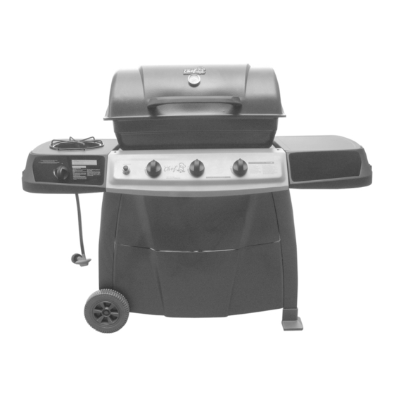
S405 Barbecue
Assembly Manual
85-3023-6 (G43705) Propane
1 YeAr liMited WArrAntY
reAd And sAve MAnuAl for future reference.
if pre-assembled, leave this manual with unit for
consumer's future reference.
for product inquiries, parts, warranty and
troubleshooting support, please call 1-877-707-5463.
Manual Revision #: 24112009 PD
Advertisement

Related Manuals for Master Chef S405


Summary of Contents for Master Chef S405
- Page 1 S405 Barbecue Assembly Manual 85-3023-6 (G43705) Propane 1 YeAr liMited WArrAntY reAd And sAve MAnuAl for future reference. if pre-assembled, leave this manual with unit for consumer’s future reference. for product inquiries, parts, warranty and troubleshooting support, please call 1-877-707-5463.
-
Page 2: Hardware Pack
HARDWARE PACK tools needed for AsseMBlY KeY # description pArt nuMBer QuAntitY No. 10-24 x 13 Screw 20124-10013-036 • #2 Phillips screwdriver (long and short) No. 10-24 x 30 Screw 20124-10030-036 No. 10 Nut 31224-10000-036 • ¼” Slotted screwdriver (long and short) Hinge Pin G306-0005-9088 •... - Page 3 PARts List (PRoPANE) foR 85-3023-6 (G43705) EXPLoDED DiAGRAM (PRoPANE) foR 85-3023-6 (G43705) KeY # QuAntitY description pArt no. Top lid assembly G437-0054-01 Thermometer G305-0039-01 Logo G451-0001-01 Upper hinge G206-0002-A2 Top lid handle G306-0002-01 Rubber pad G303-0038-01 Burner box assembly G437-5400-01 Lower hinge G210-0019-01 Burner...
-
Page 4: Assembly Instructions
AssEMBLY iNstRUCtioNs AssEMBLY iNstRUCtioNs tWo people reQuired for All a. Assemble the upper front panel (DE) to the left and right, front cart side panels (DB & DA), AsseMBlY steps as shown. Assemble the tank retainer clip (DL) to the left YOU WILL NEED: cart side panel (DB), as shown in Figure B. - Page 5 AssEMBLY iNstRUCtioNs AssEMBLY iNstRUCtioNs a. Assemble the valve assembly (CB) to the a. Insert the front and back end caps (DH & DI) control panel (CA). to the bottom of the right cart panel (DA), as shown. YOU WILL NEED: b.
- Page 6 AssEMBLY iNstRUCtioNs AssEMBLY iNstRUCtioNs a. Assemble the top lid handle (AE) to the top lid a. Assemble the lower hinge (BB x2) on the back (AA). of the burner box assembly (BA) as shown. YOU WILL NEED: YOU WILL NEED: b.
- Page 7 AssEMBLY iNstRUCtioNs AssEMBLY iNstRUCtioNs Assemble the lid (AA) to the Burner box (BA), as Install the hardware into the burner box shown in figure A&B. assembly (BA) to support the flame tamer (BF). YOU WILL NEED: YOU WILL NEED: Position the flame tamer (BF) onto the hardware Connect the main burner electrode wire (BE), assembled in step 12.
- Page 8 AssEMBLY iNstRUCtioNs AssEMBLY iNstRUCtioNs Attach the grease cup hook (CH) to the bottom of Assemble right side shelf table (EA), and left side the burner box assembly (BA) as shown. Position burner table (EC) to the left and right cart side the grease cup (CI) into the grease cup hook (CH), panels , as shown.
- Page 9 AssEMBLY iNstRUCtioNs AssEMBLY iNstRUCtioNs a. Assemble the side burner valve (CD) onto the a. Attach the side burner shelf fascia (ED) to the control panel of the side burner table (EC), as side burner shelf table (EC) and the control shown.
- Page 10 AssEMBLY iNstRUCtioNs AssEMBLY iNstRUCtioNs lp cYlinder is sold sepArAtelY. a. Use the side burner clip (#12) to secure the side burner orifice to the side burner valve (CD). Fill and leak test the LP cylinder before attaching to BBQ. Once LP cylinder has been filled and YOU WILL NEED: leak checked, locate the tank support bar on the bottom of the left cart side panel and place LP...
Need help?
Do you have a question about the S405 and is the answer not in the manual?
Questions and answers