Table of Contents
Advertisement
Quick Links
Advertisement
Table of Contents

Related Manuals for Commell LE-375


Summary of Contents for Commell LE-375
- Page 1 LE-375 3.5 inch Miniboard User’s Manual Edition 1.0 2009/10/20...
- Page 3 LE-375 User’s Manual Copyright Copyright 2009. All rights reserved. This document is copyrighted and all rights are reserved. The information in this document is subject to change without prior notice to make improvements to the products. This document contains proprietary information and protected by copyright. No part of this document may be reproduced, copied, or translated in any form or any means without prior written permission of the manufacturer.
-
Page 4: Oaldc
LE-375 User’s Manual Packing List: Please check the package content before you starting using the board. Hardware: LE-375 3.5“ Miniboard x 1 Cable Kit: 44-pin 44-pin 40-pin DC Power Cable x 1 (OALDC-2) IDE Cable x 1 (OALUDMA33-8) 1 to 3 power output cable... - Page 5 LE-375 User’s Manual Index Chapter 1 <Introduction> ..............6 1.1 <Product Overview>....................6 1.2 <Product Specification> ..................7 1.3 <Mechanical Drawing> ..................9 1.4 <Block Diagram> ....................10 Chapter 2 <Hardware Setup> ............. 11 2.1 <Connector Location> ..................11 2.2 <Jumper Reference>....................13 2.3 <Connector Reference> ..................14 2.3.1 <Internal Connector>...
- Page 6 LE-375 User’s Manual Chapter 3 <BIOS Setup> ..............33 Appendix A <I/O Port Pin Assignment> ......35 A.1 <IDE Port> ......................35 A.2 <IrDA Port>......................35 A.3 <SMBUS Port> ....................36 A.4 <LPC Port> ......................36 A.5 < CRT Port > ...................... 36 A.6 <Serial Port>.......................
- Page 7 LE-375 User’s Manual (This page is left for blank)
-
Page 8: Chapter 1
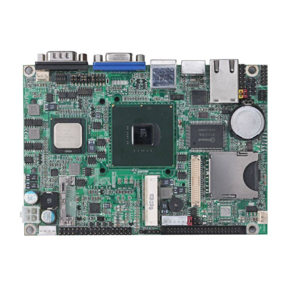
Chapter 1 <Introduction> 1.1 <Product Overview> LE-375 is the 3.5 inch miniboard, with Intel® Atom Z510P processor for 400 MHz front side bus, Intel® US15WP SCH, integrated GMA500 graphics, DDR2 SO-DIMM memory, Realtek HD Audio, CF, SD and one Intel® 82574L Gigabit LAN. -
Page 9: Product Specification
LE-375 User’s Manual 1.2 <Product Specification> General Specification Form Factor 3.5 inch miniboard Intel® Atom Z510P processor Package type: 437pin FCBGA8 with an IHS Front side bus: 400MHz Memory 1 x 200-pin DDR2 SO-DIMM SDRAM up to 2GB Unbufferred, none-ECC memory supported only Chipset Intel®... - Page 10 LE-375 User’s Manual Ethernet Interface Controller 1 x Intel® 82574L Gigabit Ethernet controller Type Triple speed 10/100/1000Base-T auto-switching Fast Ethernet Full duplex, IEEE802.3U compliant Connector One External RJ45 connector with LED Audio Interface Chipset REALTEK ALC888 Interface Stereo audio Line-out and MIC-in...
-
Page 11: Mechanical Drawing
LE-375 User’s Manual 1.3 <Mechanical Drawing> Unit: inch... -
Page 12: Block Diagram
LE-375 User’s Manual 1.4 <Block Diagram> DDR2 SODIMM 2GB max. PCIE mini card socket PCIE Giga LAN 24bit Single Channel LVDS IDE & Compact Flash CRT / DVI / LVDS SDIO W83627DHG 6 x USB port Serial Port HD Audio... -
Page 13: Chapter 2
LE-375 User’s Manual Chapter 2 <Hardware Setup> 2.1 <Connector Location> CN_SMBUS CN_USB1/2 DC_OUT CN_INV SYSFAN CN_LVDS JFRNT DC_IN MINI_CARD CN_IR CDIN CN_DIO CN_LPC CN AUDIO CN_COM2 CPUFAN... - Page 14 LE-375 User’s Manual DDRII LE-375QT RJ45 COM1 LE-375QD HDMI LE-375QX...
-
Page 15: Jumper Reference
LE-375 User’s Manual 2.2 <Jumper Reference> Jumper Function JRTC CMOS Operating/Clear Setting JVLCD LCD Panel Voltage Setting AT/ATX Mode Setting JCSEL1/2 COM2 RS232/422/485/IrDA Mode Setting JVLCD JRTC JCSEL2 JCSEL1... -
Page 16: Connector Reference
LE-375 User’s Manual 2.3 <Connector Reference> 2.3.1 <Internal Connector> Connector Function Remark DDRII 200 -pin DDR2 SO-DIMM SDRAM slot Standard 44-pin primary IDE connector Slim Compact Flash Type II socket Standard MINI_CARD PCIE mini card socket Standard CN_LVDS 20 x 2-pin LVDS connector... -
Page 17: Cpu And Memory Setup
LE-375 User’s Manual 2.4 <CPU and Memory Setup> The board provides one 200-pin DDR2 SO-DIMM to support DDR2 400 memory modules up to 2GB of capacity. Non-ECC, unbuffered memory is supported only. DDRII... -
Page 18: Cmos & Atx Setup
LE-375 User’s Manual 2.5 <CMOS & ATX Setup> The board’s data of CMOS can be setting in BIOS. If the board refuses to boot due to inappropriate CMOS settings, here is how to proceed to clear (reset) the CMOS to its default values. -
Page 19: Enhanced Ide & Cf Interface
LE-375 User’s Manual 2.6 <Enhanced IDE & CF Interface> The board has one Ultra DMA33 IDE interface to support up to 2 ATAPI devices and one Compact Flash Type II socket on the solder side. -
Page 20: Sdio Interface
LE-375 User’s Manual 2.7 <SDIO Interface> Based on Intel® SCH, the board provides One SDIO interfaces with SD slot 2.8 <LAN Interface> The Intel® 82574L supports triple speed of 10/100/1000Base-T, with IEEE802.3 compliance and Wake-On-LAN supported. -
Page 21: Onboard Display Interface
LE-375 User’s Manual 2.9 <Onboard Display Interface> Based on Intel® SCH chipset with built-in GMA (Graphic Media Accelerator) 500 graphics, the board provides one DB15 or HDMI connector on real external I/O port, and one 40-pin LVDS interface with 5-pin LCD backlight inverter connector. The board provides dual display function with clone mode and extended desktop mode for CRT, DVI and LVDS. -
Page 22: Digital Display
LE-375 User’s Manual 2.9.2 <Digital Display> The board provides one 40-pin LVDS connector for 18 or 24 bit dual channel panels, supports up to 1920 x 1080 (WUXGA) of resolution, with one LCD backlight inverter connector and one jumper for panel voltage setting... - Page 23 LE-375 User’s Manual Connector: CN_INV Jumper: JVLCD Type: 5-pin Inverter power connector Type: 3-pin Power select jumper Connector model: JST B5B-XH-A Description Description +12V +3.3V +12V Default: 1-2 ENABKL Connector: CN_LVDS Type: onboard 40-pin connector for LVDS connector Connector model: HIROSE DF13-40DP-1.25V...
- Page 24 LCD Installation Guide: Preparing the LE-375, LCD panel and the backlight inverter Please check the datasheet of the panel to see the voltage of the panel, and set the jumper JVLCD to +5V or +3.3V.
- Page 25 LE-375X BIOS panel type selection form On board Dual channel LVDS Output format 1280 x 1024 24bit The LE-375QX supports dual channel 24bit LVDS, if need support other resolution flat panel, please contact Commell tech support team for customize BIOS and driver.
- Page 26 LE-375 User’s Manual 2.9.3 <DVI Interface >(LE-375QD only) The board also comes with a DVI interface with Chrontel CH7307C for digital video interface. Supports up to 1600 x 1200 (UXGA) of resolution. Connector: HDMI Connector type: 19-pin Type A HDMI connector...
-
Page 27: Onboard Audio Interface
LE-375 User’s Manual 2.10 <Onboard Audio Interface> The board provides the onboard high definition audio with Realtek ALC888 Connector: CN_AUDIO Type: 10-pin (2 x 5) 1.27mm x 2.54mm-pitch header Description Description MIC_L Ground MIC_R AVCC SPK_R MIC_JD SENSE SPK_L SPK_JD Connector: CDIN Type: 4-pin header (pitch = 2.54mm) -
Page 28: Usb2.0 Interface
LE-375 User’s Manual 2.11 <USB2.0 Interface> Based on Intel® SCH , the board provides 6 USB2.0 ports. The USB2.0 interface provides up to 480Mbps of transferring rate. Interface USB2.0 Controller US15WP Transfer Rate Up to 480Mb/s Output Current 500mA CN_USB1/2... -
Page 29: Gpio Interface
LE-375 User’s Manual 2.12 <GPIO Interface> The board provides a programmable 8-bit digital I/O interface; you can use this general purpose I/O port for system control like POS or KIOSK. Connector: CN_DIO Type: onboard 2 x 6-pin header, pitch=2.0mm Description... -
Page 30: Serial Port Jumper Setting
LE-375 User’s Manual 2.13 <Serial Port Jumper Setting > The board provides two RS232 serial ports, with jumper selectable RS422/485/IrDA for COM2. Connector: CN_COM2 Type: 10-pin (5 x 2) 1.27mm x 2.54mm-pitch header for COM2 Description Description DCD/422TX-/485- RXD/422TX+/485+ TXD/422RX+... -
Page 31: Power & Fan Connector
LE-375 User’s Manual 2.14 <Power & FAN Connector > The board requires DC input with 4-pin header, the input voltage range is from 9V to 24V, for the input current, please take a reference of the power consumption report on appendix. -
Page 32: Power Output
LE-375 User’s Manual 2.14.2 <Power Output> Connector: DC_OUT Type: 4-pin connector for +5V/+12V output Pin Description Pin Description Pin Description Pin Description +12V Ground Ground Note: Maximum output current 12V/3A, 5V/3A 2.14.3 <Fan Connector> Connector: SYSFAN, CPUFAN Type: 3-pin fan wafer connector... -
Page 33: Indicator And Switch
LE-375 User’s Manual 2.15 <Indicator and Switch> The JFRNT provides front control panel of the board, such as power button, reset and beeper, etc. Please check well before you connecting the cables on the chassis. Connector: JFRNT Type: onboard 14-pin (2 x 7) 2.54-pitch header... - Page 34 LE-375 User’s Manual (This Page is Left For Blank)
-
Page 35: Chapter 3
LE-375 User’s Manual Chapter 3 <BIOS Setup> The motherboard uses the Award BIOS for the system configuration. The Award BIOS in the single board computer is a customized version of the industrial standard BIOS for IBM PC AT-compatible computers. It supports Intel® x86 and compatible CPU architecture based processors and computers. - Page 36 LE-375 User’s Manual (This Page is Left for Blank)
-
Page 37: Appendix A
LE-375 User’s Manual Appendix A <I/O Port Pin Assignment> A.1 <IDE Port> Connector: IDE Type: 44-pin (22 x 2) box header Description Description Reset Ground Ground Ground IOW-/STOP Ground IOR-/HDMARDY Ground IORDY/DDMARDY Ground DACK- Ground ASP1 Ground Ground Ground A.2 <IrDA Port>... -
Page 38: A.3
LE-375 User’s Manual A.3 <SMBUS Port> Connector: CN_SMBUS Type: 5-pin header for SMBUS Port Description SMDATA SMCLK Ground A.4 <LPC Port> Connector: CN_LPC Type: 10-pin header for LPC Port Description Description LPC_CLK RESET- LFRAME- LAD3 LAD2 LAD1 LAD1 +3.3V Ground Ground A.5 <... -
Page 39: A.6
LE-375 User’s Manual A.6 <Serial Port> Connector: COM1 Type: 9-pin D-sub male connector on rear panel Description Description Ground A.7 <LAN Port> Connector: RJ45 Type: RJ45 connector with LED on rear panel Description TRD0+ TRD0- TRD1+ TRD2+ TRD2- TRD1- TRD3+ TRD3-... -
Page 40: Appendix B
LE-375 User’s Manual Appendix B <Flash BIOS> B.1 BIOS Auto Flash Tool The board is based on Award BIOS and can be updated easily by the BIOS auto flash tool. You can download the tool online at the address below: http://www.award.com... -
Page 41: Appendix C
LE-375 User’s Manual Appendix C <System Resources> C.1 <I/O Port Address Map>... - Page 42 LE-375 User’s Manual...
-
Page 43: C.2
LE-375 User’s Manual C.2 <Memory Address Map >... -
Page 44: C.3 < System Irq Resources
LE-375 User’s Manual C.3 < System IRQ Resources >... -
Page 45: Appendix D
LE-375 User’s Manual Appendix D <Programming GPIO’s> The GPIO can be programmed with the MS-DOS debug program using simple IN/OUT commands.The following lines show an example how to do this. GPIO0…..GPIO7 bit0……bit7 -o 2E 87 ;enter configuration. -o 2E 87... -
Page 46: Appendix E
LE-375 User’s Manual Appendix E <Watch Dog timer Setting > The watchdog timer makes the system auto-reset while it stops to work for a period. The integrated watchdog timer can be setup as system reset mode by program. Timeout Value Range... - Page 47 LE-375 User’s Manual (This Page is Left for Blank)
-
Page 48: Contact Information
Taiwan Commate Computer Inc. Address 19 F No. 94, Sec. 1, Shin Tai Wu Rd., Shi Chih Taipei Hsien, Taiwan +886-2-26963909 +886-2-26963911 Website h ttp://www.commell.com.tw E-Mail i nfo@commell.com.tw (General Information) t ech@commell.com.tw (Technical Support) Commell is our trademark of industrial PC division...
Need help?
Do you have a question about the LE-375 and is the answer not in the manual?
Questions and answers