Table of Contents
Advertisement
Quick Links
Advertisement
Table of Contents

Related Manuals for Commell LS-570


Summary of Contents for Commell LS-570
- Page 1 LS-570 5.25 inch Embedded Miniboard User’s Manual Edition 1.3 2011/03/10...
- Page 2 LS-570 User’s Manual Copyright Copyright 2006. All rights reserved. This document is copyrighted and all rights are reserved. The information in this document is subject to change without prior notice to make improvements to the products. This document contains proprietary information and protected by copyright. No part of this document may be reproduced, copied, or translated in any form or any means without prior written permission of the manufacturer.
-
Page 3: Packing List
LS-570 User’s Manual Packing List Please check the package before you starting setup the system Hardware: LS-570 series motherboard x 1 Cable Kit: 44-pin 40-pin 44-pin PS2 Cable x 1 ATA33 IDE Cable x1 SATA Cable x 2 26-pin Slim Type Floppy Cable x 1 Power Cable x 1 COM &... - Page 4 LS-570 User’s Manual CPU Cooler x 1 USB Cable x 1 Printed Matters: Driver CD x 1 (Including User’s Manual)
- Page 5 LS-570 User’s Manual Index Chapter 1 <Introduction> ..................8 1.1 <Product Overview>................. 8 1.2 <Product Specification> ................9 1.3 <Mechanical Drawing>................11 1.4 <Block Diagram>..................12 Chapter 2 <Hardware Setup>................13 2.1 <Connector Location>................13 2.2 <Jumper Reference> ................15 2.3 <Connector Reference>.................
- Page 6 LS-570 User’s Manual 2.15.2 <Power Output> ............... 38 2.15.3 <Fan Connector>..............38 2.16 <Indicator and Switch>................. 39 Chapter 3 <System Configuration>..............41 3.1 <Video Memory Setup> ................. 41 Chapter 4 <BIOS Setup> ..................45 Appendix A <I/O Port Pin Assignment> ............47 A.1 <IDE Port>...
- Page 7 LS-570 User’s Manual (The Page is Left For Blank)
-
Page 8: Chapter 1
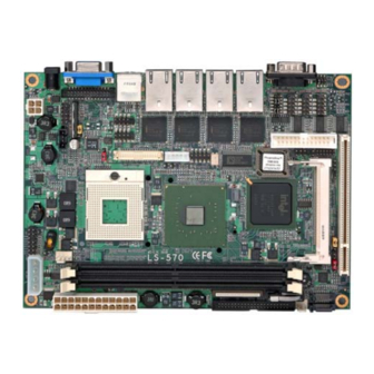
Chapter 1 <Introduction> 1.1 <Product Overview> LS-570 is the 5.25 inch Embedded miniboard, with supporting Intel Core Duo/Core Solo processors for 533/667MHz front side bus, Intel 945GM(E) and ICH7-M chipset, integrated GMA950 graphics, DDR2 memory, Realtek AC97 Audio, Serial ATA and four Intel 82537L Gigabit LAN . -
Page 9: Product Specification
LS-570 User’s Manual Introduction 1.2 <Product Specification> General Specification Form Factor 5.25 inch miniboard Intel® Core Duo/Core Solo processor Package type: Micro- FCPGA478 Front side bus: 533/667MHz Memory 2 x 240-pin DDR2 533/667MHz SDRAM up to 3GB Up to 10.67GB/s of bandwidth with dual-channel interleaved mode... - Page 10 LS-570 User’s Manual Introduction Onboard 26-Pin DVI connector Onboard 10-Pin TV-out connector Ethernet Interface Controller 4 x Intel 82573L Gigabit Ethernet controller Type Triple speed 10/100/1000Base-T auto-switching Fast Ethernet Full duplex, IEEE802.3U compliant Connector Four External RJ45 connector with LED on rear I/O panel...
-
Page 11: Mechanical Drawing
LS-570 User’s Manual Introduction 1.3 <Mechanical Drawing> Mechanical Drawing... -
Page 12: Block Diagram
LS-570 User’s Manual Introduction 1.4 <Block Diagram> Intel Yonah Processor 2 x 240-pin DDR2 533/677MHz Intel GMA950 Graphics up to 3GB HDTV&LVDS&DVI 945GM(E) 2 x SATA CompactFlash&IDE AC97 ALC655 6 x USB2.0 ports ICH7-M Intel 82537L 4 x GLAN Fintek... -
Page 13: Chapter 2
LS-570 User’s Manual Hardware Setup Chapter 2 <Hardware Setup> 2.1 <Connector Location> DDRII_A/B CPUFAN SYSFAN SATA1/2 DC_OUT JFRNT MINIPCI CN_LVDS CN_IR CN_DIO CN_INV CD_IN CN_LPT CN_PS2 CN_DVI CN_COM2/3/4 CN_HDTV CN_USB1/2 CN_AUDIO Connector Location... - Page 14 LS-570 User’s Manual Hardware Setup COM1 LAN1/2/3/4 DC_IN Connector Location...
-
Page 15: Jumper Reference
LS-570 User’s Manual Hardware Setup 2.2 <Jumper Reference> Jumper Function JRTC CMOS Operating/Clear Setting JCFSEL Compact Flash address mode setting JVLCD LCD Panel Voltage Setting JCRT CRT attach select setting Power mode select JCSEL1/2 COM2 RS232/422/485 mode setting Jumper: JAT... -
Page 16: Connector Reference
LS-570 User’s Manual Hardware Setup 2.3 <Connector Reference> 2.3.1 <Internal Connector> Connector Function Remark DDRIIA/B 240 -pin DDR2 SDRAM DIMM slot Standard 44-pin primary IDE connector Slim 26-pin slim type floppy connector Slim SATA1/2 7-pin Serial ATA connector Standard CN_12V... -
Page 17: Cpu And Memory Setup
LS-570 User’s Manual Hardware Setup 2.4 <CPU and Memory Setup> 2.4.1< CPU> The board comes with the socket479 for Intel Core Duo/Core Solo processor , it supports new generation of Intel Core Duo processor with 533/667MHz of front side bus and 2MB L2 cache. -
Page 18: Memory
LS-570 User’s Manual Hardware Setup 2.4.2 <Memory> T The board provides two 240-pin DDR2 DIMMs to support DDR2 533/667 memory modules up to 3GB of capacity. Non-ECC, unbuffered memory is supported only. While applying two same modules, dual channel technology is enabled automatically for higher performance. -
Page 19: Cmos Atx Setup
LS-570 User’s Manual Hardware Setup 2.5 <CMOS ATX Setup> The board’s data of CMOS can be setting in BIOS. If the board refuses to boot due to inappropriate CMOS settings, here is how to proceed to clear (reset) the CMOS to its default values. -
Page 20: Enhanced Ide & Cf Interface
LS-570 User’s Manual Hardware Setup 2.6 <Enhanced IDE & CF Interface> The board has one Ultra DMA33 IDE interface to support up to 2 ATAPI devices, and one Compact Flash Type II socket on the solder side. The board also provides a Compact Flash Type II socket with jumper (JCFSEL) selectable slave/Master mode on secondary IDE channel. -
Page 21: Serial Ata Interface
LS-570 User’s Manual Hardware Setup 2.7 <Serial ATA Interface> Based on Intel ICH7-M, the board provides two Serial ATA interfaces with up to 150MB/s of transfer rate SATA1/2 Serial ATA Interface... -
Page 22: Floppy Port
LS-570 User’s Manual Hardware Setup 2.8 <Floppy Port> The board provides a slim type floppy port; please use the 26-pin ribbon cable in the package to connect the floppy device. Floppy rear side Lift up this plastic bar Slot the cable in (Blue paste for outside) -
Page 23: Lan Interface
LS-570 User’s Manual Hardware Setup 2.9 <LAN Interface> The Intel 82573L supports triple speed of 10/100/1000Base-T, with IEEE802.3 compliance and Wake-On-LAN supported. LAN_1/2/3/4 2.10 <Onboard Display Interface> Based on Intel 945GM(E) chipset with built-in GMA (Graphic Media Accelerator) 950 graphics, the board provides one DB15 connector on real external I/O port, and one 40-pin LVDS interface with 5-pin LCD backlight inverter connector. -
Page 24: Digital Display
LS-570 User’s Manual Hardware Setup 2.10.2 <Digital Display> The board provides one 40-pin LVDS connector for 18/24-bit single/dual channel panels, supports up to 1600 x 1200 (UXGA) of resolution, with one LCD backlight inverter connector and one jumper for panel voltage setting... - Page 25 LS-570 User’s Manual Hardware Setup Connector: CN_INV Connector: JVLCD Type: 5-pin LVDS Power Header Type: 3-pin Power select Header Connector model: JST B5B-XH-A Description Description +12V VCC(5V) LCDVCC VCC3(3.3) ENABKL Connector: CN_LVDS Type: onboard 40-pin connector for LVDS connector Connector model: HIROSE DF13-40DP-1.25V...
- Page 26 LCD Installation Guide: Preparing the LS-570, LCD panel and the backlight inverter. Please check the datasheet of the panel to see the voltage of the panel, and set the jumper JVLCD to +5V or +3.3V.
-
Page 27: Dvi Interface
LS-570 User’s Manual Hardware Setup 2.10.3 <DVI Interface > The board also comes with a DVI interface with Chrontel CH7307C for digital video interface. Connector: CN_DVI Connector type: 26-pin header connector (pitch = 2.00mm) Pin Number Assignment Pin Number Assignment... -
Page 28: Tv-Out Interface
LS-570 User’s Manual Hardware Setup 2.10.4<TV-out Interface> The board provides an HDTV interface with Intel 945GM(E), supports PAL and NTSC of TV system, and display (clone or extended desktop) function with CRT,LVDS,DVI. Connector: CN_HDTV Connector type: 10-pin header HDTV connector (pitch = 2.54mm) - Page 29 LS-570 User’s Manual Hardware Setup To connect the TV set, please follow the diagram below to setup your system: YPrPb Component Cable (For HDTV) TV-out Interface...
- Page 30 LS-570 User’s Manual Hardware Setup After setup the devices well, you need to select the LCD panel type in the BIOS. The panel type mapping is list below: BIOS panel type selection form 18 bits Single channel 24 bits Dual channel...
-
Page 31: Onboard Audio Interface
LS-570 User’s Manual Hardware Setup 2.11 <Onboard Audio Interface> The board provides the onboard AC97 5.1-channel audio interface with Realteck ALC655. Connector: CN_AUDIO Type: 10-pin (2 x 5) header (pitch = 2.54mm) Description Description Line/SURR – Left Ground Line/SURR – Right... -
Page 32: Usb2.0 Interface
LS-570 User’s Manual Hardware Setup 2.12 <USB2.0 Interface> Based on Intel ICH7-M , the board provides 4USB2.0 ports. The USB2.0 interface provides up to 480Mbps of transferring rate. Interface USB2.0 Controller ICH7-M Transfer Rate Up to 480Mb/s Output Intensity 500mA CN_USB USB2.0 Interface... - Page 33 LS-570 User’s Manual Hardware Setup Connector: CN_USB Type: 10-pin (5 x 2) header for USB1/2 Ports Description Description Data0- Data1- Data0+ Data1+ Ground Ground Ground PS: The USB2.0 will be only active when you connecting with the USB2.0 devices, if you insert an USB1.1 device, the port will be changed to USB1.1 protocol automatically.
-
Page 34: Gpio Interface
LS-570 User’s Manual Hardware Setup 2.13 <GPIO Interface> The board provides a programmable 8-bit digital I/O interface; you can use this general purpose I/O port for system control like POS or KIOSK. Connector: CN_DIO Type: onboard 2 x 6-pin header, pitch=2.0mm... -
Page 35: Serial Port Jumper Setting
LS-570 User’s Manual Hardware Setup 2.14 <Serial Port Jumper Setting > The board provides three RS232 serial ports, with jumper selectable RS422/485 for COM2. Connector: CN_COM2/3/4 Type: 10-pin (5 x 2) header for COM2/3/4 Description Description DCD/422TX-/485- RXD/422TX+/485+ TXD/422RX+ DTR/422RX-... - Page 36 LS-570 User’s Manual Hardware Setup JCSEL2 CN_COM2/3/4 JCSEL1 Serial Port Jumper Setting...
-
Page 37: Power Input
LS-570 User’s Manual Hardware Setup 2.15 <Power and Fan Connector> The board requires DC input with 2-pin DC-Jack power connector on rear I/O panel, or onboard 4-pin ATX2.0 12V connector, the input voltage range is from 8V to 24V, for the input current, please take a reference of the power consumption report on appendix. -
Page 38: Power Output
LS-570 User’s Manual Hardware Setup 2.15.2 <Power Output> Connector: DC_OUT Type: 4-pin P-type connector for +5V/+12V Description Description Description Description Ground Ground +12V Note: Maximum output voltage: 12V/5A & 5V/3A Floppy ATAPI Drives Relative Accessory 2.15.3 <Fan Connector> Connector: SYSFAN... -
Page 39: Indicator And Switch
LS-570 User’s Manual Hardware Setup 2.16 <Indicator and Switch> The JFRNT provides front control panel of the board, such as power button, reset and beeper, etc. Please check well before you connecting the cables on the chassis. Connector: JFRNT Type: onboard 14-pin (2 x 7) 2.54-pitch header... - Page 40 LS-570 User’s Manual (This Page is Left For Blank)
-
Page 41: Chapter 3
LS-570 User’s Manual System Configuration Chapter 3 <System Configuration> 3.1 <Video Memory Setup> Based on Intel® 945GM(E) chipset with GMA (Graphic Media Accelerator) 950, the board supports Intel® DVMT (Dynamic Video Memory Technology) 3.0, which would allow the video memory to be allocated up to 224MB. - Page 42 LS-570 User’s Manual System Configuration Fixed + DVMT Memory Size: You can select the fixed amount and the DVMT amount at the same time for a guaranteed video memory and additional dynamic video memory, please check the table below for available setting.
- Page 43 LS-570 User’s Manual System Configuration 3.2 <Audio Configuration> The board provides 5.1 channel audio interface with driver installed, please install the Realtek ALC655 audio driver in the CD before getting start to enjoy the 5.1 channel sound system. Audio Configuration...
- Page 44 LS-570 User’s Manual (This Page is Left for Blank)
-
Page 45: Chapter 4
LS-570 User’s Manual BIOS Setup Chapter 4 <BIOS Setup> The motherboard uses the Award BIOS for the system configuration. The Award BIOS in the single board computer is a customized version of the industrial standard BIOS for IBM PC AT-compatible computers. It supports Intel x86 and compatible CPU architecture based processors and computers. - Page 46 LS-570 User’s Manual (This Page is Left for Blank)
-
Page 47: Appendix A
LS-570 User’s Manual I/O Port Pin Assignment Appendix A <I/O Port Pin Assignment> A.1 <IDE Port> Connector: IDE Type: 44-pin (22 x 2) box header Description Description Reset Ground Ground Ground IOW-/STOP Ground IOR-/HDMARDY Ground IORDY/DDMARDY Ground DACK- Ground ASP1... -
Page 48: A.2
LS-570 User’s Manual I/O Port Pin Assignment A.2 <Floppy Port> Connector: FDD Type: 26-pin connector Description Description INDEX DRV0 DSKCHG DRV1 MTR1 MTR0 STEP Ground WRITE DATA Ground WRITE GATE TRACK 0 WRPTR Ground RDATA- Ground A.3 <IrDA Port> Connector: CN_IR... -
Page 49: A.4 < Crt Port
LS-570 User’s Manual I/O Port Pin Assignment A.4 < CRT Port > Connector: CRT Type: 15-pin D-sub female connector on panel Description Description Description Ground GREEN Ground 5VCDA BLUE Ground HSYNC LVGA5V VSYNC Ground Ground 5VCLK A.5 <Serial ATA Port>... -
Page 50: A.7
LS-570 User’s Manual I/O Port Pin Assignment A.7 <LAN Port> Connector: RJ45_1/2/3/4 Type: RJ45 connector with LED on rear panel Description A.8 <Parallel Port> Connector: LPT (PRINTER) Type: 26-pin (2 x 13) 2.54-pitch box header Description Description STROBE- AUTO FEED-... -
Page 51: Appendix B
LS-570 User’s Manual Flash BIOS Appendix B <Flash BIOS> B.1 BIOS Auto Flash Tool The board is based on Award BIOS and can be updated easily by the BIOS auto flash tool. You can download the tool online at the address below: http://www.award.com... -
Page 52: Appendix C
LS-570 User’s Manual System Resources Appendix C <System Resources> C1.<I/O Port Address Map> I/O Port Address Map... - Page 53 LS-570 User’s Manual System Resources I/O Port Address Map...
- Page 54 LS-570 User’s Manual System Resources C2.<Memory Address Map> Memory Address Map...
- Page 55 LS-570 User’s Manual System Resources C3.<System IRQ Resources> System IRQ Resources...
-
Page 56: Appendix D
LS-570 User’s Manual Watch Dog timer Setting Appendix D <Watch Dog timer Setting > The watchdog timer makes the system auto-reset while it stops to work for a period. The integrated watchdog timer can be setup as system reset mode by program. - Page 57 LS-570 User’s Manual (This Page is Left for Blank)
-
Page 58: Contact Information
19F., No.94, Sec. 1, Xintai 5th Rd., Xizhi Dist., New Taipei City Address 22102, Taiwan +886-2-26963909 +886-2-26963911 Website h ttp://www.commell.com.tw i nfo@commell.com.tw (General Information) E-Mail t ech@commell.com.tw (Technical Support) Facebook https://www.facebook.com/pages/Taiwan-Commate-Computer-Inc/547993955271899 Twitter https://twitter.com/Taiwan_Commate Commell is our trademark of industrial PC division Contact Information...
Need help?
Do you have a question about the LS-570 and is the answer not in the manual?
Questions and answers