
Related Manuals for Commell LE-565


Summary of Contents for Commell LE-565
- Page 1 All manuals and user guides at all-guides.com LE-565 5.25 inch Embedded Miniboard User’s Manual Edition 1.0 2006/06/19...
- Page 2 All manuals and user guides at all-guides.com LE-565 User’s Manual Copyright Copyright 2006. All rights reserved. This document is copyrighted and all rights are reserved. The information in this document is subject to change without prior notice to make improvements to the products.
-
Page 3: Packing List
All manuals and user guides at all-guides.com LE-565 User’s Manual Packing List Please check the package before you starting setup the system Hardware: LE-565 series motherboard x 1 Cable Kit: Serial ATA Ribbon Cable x 2 PS2 Cable x 1 44-pin ATA33 IDE Cable x 1... - Page 4 All manuals and user guides at all-guides.com LE-565 User’s Manual Index Chapter 1 <Introduction> ..................7 1.1 <Product Overview>................. 7 1.2 <Product Specification> ................8 1.3 <Mechanical Drawing>............... …10 1.4 <Block Diagram>..................11 Chapter 2<Hardware Setup>……………………………………………….……..12 2.1 <Connector Location> ..............……12 2.2 <Jumper Reference>………………………………………………………..14...
- Page 5 All manuals and user guides at all-guides.com LE-565 User’s Manual 2.15.1 <Power Input> ................33 2.15.2 <Power Output>…………………………………………………….34 2.15.3 <Fan Connector>..............34 2.16 <Indicator and Switch>................. 35 Chapter 3 <System Configuration>..............37 3.1 <SATA RAID Configuration>..............37 3.2 <Audio Configuration> ................39 3.3 <Display Configuration>.................
- Page 6 All manuals and user guides at all-guides.com LE-565 User’s Manual (The Page is Left For Blank)
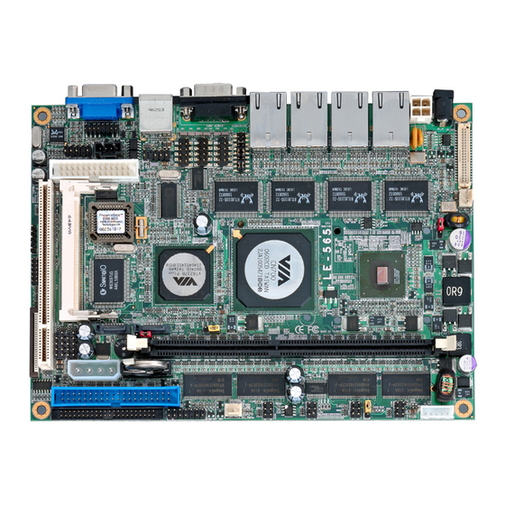
- Page 7 Chapter 1 <Introduction> 1.1 <Product Overview> LE-565 is the 5.25 inch embedded miniboard based on VIA chipset. It integrates VIA embedded chipset for CN700 with VT8237R Plus, DDR 333/400 SDRAM, and serial ATA with RAID to provide the economical embedded platform.
- Page 8 All manuals and user guides at all-guides.com LE-565 User’s Manual Introduction 1.2 <Product Specification> General Specification Form Factor 5.25 inch miniboard VIA V4/Eden 1.0GHz processor L1/L2 Cache: 128/128KB Front side bus: 400MHz Memory 1 x 184-pin DDR 333/400 SDRAM up to 1GB,onboard optional...
- Page 9 All manuals and user guides at all-guides.com LE-565 User’s Manual Introduction Ethernet Interface Chipset REALTEK 8110S-32 Type 10Base-T / 100Base-TX /1000Base-TX auto-switching Fast Ethernet Full duplex, IEEE802.3U compliant Connector Four External RJ45 connectors with LED on rear I/O panel Audio Interface...
- Page 10 All manuals and user guides at all-guides.com LE-565 User’s Manual Introduction 1.3 <Mechanical Drawing> Mechanical Drawing...
- Page 11 All manuals and user guides at all-guides.com LE-565 User’s Manual Introduction 1.4 <Block Diagram> Eden nanoBGA2 CRT/LCD Monitor VT1636 LVDS 1 x 184-pin DDR333/400 Up to 1GB CN700 Ultra V-Link 533MB/s 6 x USB2.0 Ports 2 x SATA 2 x IDE...
- Page 12 All manuals and user guides at all-guides.com LE-565 User’s Manual Hardware Setup Chapter 2 <Hardware Setup> 2.1 <Connector Location> CN_PWR JLED0/1/2/3 IDE1 CN_USB2/3 CN_INV SYSFAN JFRNT IDE2 DIMM SATA1/2 CN_DIO MINIPCI CN_IR CPUFAN CN_AUDIO CN_LVDS CN_CRT CN_12V CN_COM2/3/4 CDIN CN_PS2...
- Page 13 All manuals and user guides at all-guides.com LE-565 User’s Manual Hardware Setup DC_IN LAN1/2/3/4 COM1 Connector Location...
- Page 14 All manuals and user guides at all-guides.com LE-565 User’s Manual Hardware Setup 2.2 <Jumper Reference> Jumper Function JRTC CMOS Operating/Clear Setting JCFSEL Compact Flash address mode setting LCD Panel Voltage Setting JVLCD AT/ATX mode setting COM2 RS232/422/485 mode setting JCSEL1/2...
- Page 15 All manuals and user guides at all-guides.com LE-565 User’s Manual Hardware Setup 2.3 <Connector Reference> 2.3.1 <Internal Connector> Connector Function Remark DIMM 184-pin DDR SDRAM DIMM Standard IDE1 40-pin primary IDE connector Standard IDE2 44-pin secondary IDE connector Slim 26-pin slim type floppy connector...
- Page 16 All manuals and user guides at all-guides.com LE-565 User’s Manual Hardware Setup 2.4 <CPU and Memory Setup> 2.4.1< CPU> The board supports VIA Eden processor, default ratio is Eden 1G (400MHz) with heatsink only. 2.4.2 <Memory> The board supports one 184-pin DDR333/400 SDRAM and up to 1GB of capacity, only non-ECC, unbuffered memory is supported.
- Page 17 All manuals and user guides at all-guides.com LE-565 User’s Manual Hardware Setup 2.5 <CMOS ATX Setup> The board’s data of CMOS can be setting in BIOS. If the board refuses to boot due to inappropriate CMOS settings, here is how to proceed to clear (reset) the CMOS to its default values.
- Page 18 All manuals and user guides at all-guides.com LE-565 User’s Manual Hardware Setup 2.6 <Enhanced IDE & CF Interface> The board supports two enhanced IDE interface, dual channel for 4 ATAPI devices with ATA33. Based on embedded application, the board has one 44-pin IDE connector +5V supported for disk on module.
- Page 19 All manuals and user guides at all-guides.com LE-565 User’s Manual Hardware Setup 2.7 <Serial ATA Interface> Based on VIA VT8237R Plus Southbridge, the board supports two Serial ATA interfaces with RAID 0 and 1 array function. The following is the list of the specification of the Serial ATA.
- Page 20 All manuals and user guides at all-guides.com LE-565 User’s Manual Hardware Setup 2.8 <Floppy Port> The board provides a slim type floppy port; please use the 26-pin ribbon cable in the package to connect the floppy device. Floppy rear side...
- Page 21 All manuals and user guides at all-guides.com LS-570 User’s Manual Hardware Setup 2.9 <LAN Interface> The board provides four GigaLAN interfaces with REALTEK 8110S-32 PCI controller, and compliant with standard IEEE 802.3 Ethernet interface for 100BASE-TX. LAN_1/2/3/4 LAN Interface...
-
Page 22: Onboard Display Interface
All manuals and user guides at all-guides.com LE-565 User’s Manual Hardware Setup 2.10 <Onboard Display Interface> Based on VIA CN700, the board supports integrated S3 Graphics UniChrome Pro IGP graphics, with BIOS selectable 16/32/64MB shared with system memory for frame buffer. - Page 23 All manuals and user guides at all-guides.com LS-570 User’s Manual Hardware Setup 2.10.2 <Digital Display> The board provides one 40-pin LVDS connector for 18/24-bit single/dual channel panels, supports up to 1600 x 1200 (UXGA) of resolution, with one LCD backlight inverter connector and one jumper for panel voltage setting CN_INV JVLCD...
- Page 24 All manuals and user guides at all-guides.com LE-565 User’s Manual Hardware Setup Connector: CN_INV Connector: JVLCD Type: 5-pin LVDS Power Header Type: 3-pin Power select Header Connector model: JST B5B-XH-A Description Description +12V VCC(5V) LCDVCC VCC3(3.3) ENABKL Connector: CN_LVDS Type: onboard 40-pin connector for LVDS connector Connector model: HIROSE DF13-40DP-1.25V...
- Page 25 All manuals and user guides at all-guides.com LS-570 User’s Manual Hardware Setup To setup the LCD, you need the component below: A panel with LVDS interfaces. An inverter for panel’s backlight power. A LCD cable and an inverter cable. For the cables, please follow the pin assignment of the connector to make a cable, because every panel has its own pin assignment, so we do not provide a standard cable;...
- Page 26 LE-565 User’s Manual Hardware Setup After setup the devices well, you need to select the LCD panel type in the BIOS. The panel type mapping is list below: LE-565 BIOS panel type selection form VGA ROM VERSION: 9Y-9X-00-20 Resolution Color...
- Page 27 All manuals and user guides at all-guides.com LS-570 User’s Manual Hardware Setup 2.11 <Onboard Audio Interface> The board provides the onboard AC97 5.1-channel audio interface with Realteck ALC655. Connector: CN_AUDIO Type: 10-pin (2 x 5) header (pitch = 2.54mm) Description Description Line/SURR –...
- Page 28 All manuals and user guides at all-guides.com LE-565 User’s Manual Hardware Setup 2.12 <USB2.0 Interface> Based on VIA VT8237R Plus, the board provides 6 USB2.0 ports. The USB2.0 interface provides up to 480Mbps of transferring rate. Interface USB2.0 Controller VIA VT8237R+...
- Page 29 All manuals and user guides at all-guides.com LS-570 User’s Manual Hardware Setup Connector: CN_USB Type: 10-pin (5 x 2) header for USB2/3 Ports Description Description Data0- Data1- Data0+ Data1+ Ground Ground Ground PS: The USB2.0 will be only active when you connecting with the USB2.0 devices, if you insert an USB1.1 device, the port will be changed to USB1.1 protocol automatically.
- Page 30 All manuals and user guides at all-guides.com LE-565 User’s Manual Hardware Setup 2.13 <GPIO Interface> The board provides a programmable 8-bit digital I/O interface; you can use this general purpose I/O port for system control like POS or KIOSK. Connector: CN_DIO Type: onboard 2 x 6-pin header, pitch=2.0mm...
- Page 31 All manuals and user guides at all-guides.com LS-570 User’s Manual Hardware Setup 2.14 <Serial Port Jumper Setting > The board provides four RS232 serial ports, with jumper selectable RS422/485 for COM2. Connector: CN_COM2/3/4 Type: 10-pin (5 x 2) header for COM2/3/4 Description Description DCD/422RX-/485-...
- Page 32 All manuals and user guides at all-guides.com LE-565 User’s Manual Hardware Setup JCSEL2 JCSEL1 CN_COM2/3/4 GPIO Interface...
- Page 33 All manuals and user guides at all-guides.com LS-570 User’s Manual Hardware Setup 2.15 <Power and Fan Connector> The board comes with a 2-pin DC-Jack power connector for DC 12V input, it also has one 4-pin P4 additional use power connector for internal power supply, you can choose one pf them to meet your plication.
- Page 34 All manuals and user guides at all-guides.com LE-565 User’s Manual Hardware Setup 2.15.2 <Power Output> Connector: CN_PWR Type: 4-pin P-type connector for +5V/+12V output Description Description Description Description Ground Ground +12V Note: Maximum output voltage: 12V/5A & 5V/3A Floppy ATAPI Drives Relative Accessory 2.15.3 <Fan Connector>...
- Page 35 All manuals and user guides at all-guides.com LS-570 User’s Manual Hardware Setup 2.16 <Indicator and Switch> The JFRNT provides front control panel of the board, such as power button, reset and beeper, etc. Please check well before you connecting the cables on the chassis. Connector: JFRNT Type: onboard 14-pin (2 x 7) 2.54-pitch header Function...
- Page 36 All manuals and user guides at all-guides.com LE-565 User’s Manual (This Page is Left For Blank)
- Page 37 All manuals and user guides at all-guides.com LE-565 User’s Manual System Configuration Chapter 3 <System Configuration> 3.1 <SATA RAID Configuration> The board supports two Serial ATA ports onboard, and supports RAID 0, 1 and JBOD disk array, the RAID 0, 1 and JBOD are specified below: RAID 0 (Stripping): Two hard drives operating as one drive for optimized data R/W performance.
- Page 38 All manuals and user guides at all-guides.com LE-565 User’s Manual You also can edit disk array under OS, please install the VIA RAID Utility in the driver CD. (To getting start, please click here to learn more information) (Click here to build RAID 0)
- Page 39 All manuals and user guides at all-guides.com LE-565 User’s Manual System Configuration 3.2 <Audio Configuration> The board provides 5.1 channel audio interface with driver installed, please install the Realtek ALC655 audio driver in the CD before getting start to enjoy the 5.1 channel sound system.
- Page 40 All manuals and user guides at all-guides.com LE-565 User’s Manual 3.3 <Display Configuration> The board provides onboard analog VGA interface, and optional digital display interface with LVDS , please install the VIA video driver before enjoy the vivid display. Based on the VIA CN700 with S3 UniChrome Pro graphic, the board provides dual display function for clone or extended desktop modes with secondary display device attached.
- Page 41 All manuals and user guides at all-guides.com LE-565 User’s Manual System Configuration Two controllers for each display device There are two options for secondary display device For more display properties setting, please click “Advanced” button. Display Configuration...
- Page 42 All manuals and user guides at all-guides.com LE-565 User’s Manual Please select S3Display for advanced device setting. Connected Devices Click check box to enable/disable device Specified display setup if available When you set dual display clone mode, you’ll see the same screen display on two devices.
- Page 43 All manuals and user guides at all-guides.com LE-565 User’s Manual (This Page is Left for Blank)
- Page 44 All manuals and user guides at all-guides.com LE-565 User’s Manual BIOS Setup Chapter 4 <BIOS Setup> The motherboard uses the Award BIOS for the system configuration. The Award BIOS in the single board computer is a customized version of the industrial standard BIOS for IBM PC AT-compatible computers.
- Page 45 All manuals and user guides at all-guides.com LE-565 User’s Manual (This Page is Left for Blank)
- Page 46 All manuals and user guides at all-guides.com LE-565 User’s Manual I/O Port Pin Assignment Appendix A <I/O Port Pin Assignment> A.1 <IDE Port> Connector: IDE1 Type: 40-pin (20 x 2) box header Description Description Reset Ground Ground Ground IOW-/STOP Ground...
- Page 47 All manuals and user guides at all-guides.com LE-565 User’s Manual I/O Port Pin Assignment Connector: IDE2 Type: 44-pin (22 x 2) box header Description Description Reset Ground Ground Ground IOW-/STOP Ground IOR-/HDMARDY Ground IORDY/DDMARDY Ground DACK- Ground ASP1 Ground Ground...
- Page 48 All manuals and user guides at all-guides.com LE-565 User’s Manual I/O Port Pin Assignment A.2 <Floppy Port> Connector: FDD Type: 26-pin connector Description Description INDEX DRV0 DSKCHG DRV1 MTR1 MTR0 STEP Ground WRITE DATA Ground WRITE GATE TRACK 0 WRPTR...
- Page 49 All manuals and user guides at all-guides.com LE-565 User’s Manual I/O Port Pin Assignment A.4 < CRT Port > Connector: CRT Type: 15-pin D-sub female connector on panel Description Description Description Ground GREEN Ground 5VCDA BLUE Ground HSYNC LVGA5V VSYNC...
- Page 50 All manuals and user guides at all-guides.com LE-565 User’s Manual A.7 <LAN Port> Connector: RJ45_1/2/3/4 Type: RJ45 connector with LED on rear panel Description Connector: JLED0/1/2/3 Type: 6-pin header for LAN LED Description Description ACT+ ACT- Link100+ Link100- Link 1G+...
- Page 51 All manuals and user guides at all-guides.com LE-565 User’s Manual (This Page is Left for Blank)
-
Page 52: Bios Auto Flash Tool
All manuals and user guides at all-guides.com LE-565 User’s Manual Flash BIOS Appendix B <Flash BIOS> B.1 BIOS Auto Flash Tool The board is based on Award BIOS and can be updated easily by the BIOS auto flash tool. You can download the tool online at the address below: h ttp://www.award.com... - Page 53 All manuals and user guides at all-guides.com LE-565 User’s Manual (This Page is Left for Blank)
-
Page 54: Contact Information
Taiwan Commate Computer Inc. Address 8F, No. 94, Sec. 1, Shin Tai Wu Rd., Shi Chih Taipei Hsien, Taiwan +886-2-26963909 +886-2-26963911 Website h ttp://www.commell.com.tw E-Mail i nfo@commell.com.tw (General Information) t ech@commell.com.tw (Technical Support) Commell is our trademark of industrial PC division Contact Information...
Need help?
Do you have a question about the LE-565 and is the answer not in the manual?
Questions and answers