Table of Contents
Advertisement
Quick Links
Installation and Operation Manual
XX-204-90-00
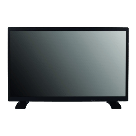
LED Monitor
Vicon Industries Inc. 131 Heartland Boulevard, Edgewood, NY 11717
Tel: 631-952-2288 Fax: 631-951-2288 Toll Free: 1-800-645-9116
24-Hour Technical Support: 800-34-VICON (800-348-4266) UK: +44 (0)1489/566300
Vicon Industries Inc. does not warrant that the functions contained in this equipment will meet your requirements or that the
operation will be entirely error free or perform precisely as described in the documentation. This system has not been designed
to be used in life-critical situations and must not be used for this purpose.
www.vicon-security.com
Document Number: 8009-8204-90-00
Issued: 0614
Copyright © 2014 Vicon Industries Inc. All rights reserved.
Advertisement
Table of Contents

Subscribe to Our Youtube Channel
Related Manuals for Vicon VM-624LED


Summary of Contents for Vicon VM-624LED
- Page 1 24-Hour Technical Support: 800-34-VICON (800-348-4266) UK: +44 (0)1489/566300 Vicon Industries Inc. does not warrant that the functions contained in this equipment will meet your requirements or that the operation will be entirely error free or perform precisely as described in the documentation. This system has not been designed to be used in life-critical situations and must not be used for this purpose.
-
Page 3: Table Of Contents
Contents Important Safeguards ......................2 ~ 3 Cautions ..........................FCC Notice ........................Connecting with external equipment ................. Remote functions ......................Controls and functions ....................... 8 ~ 15 Mounting guide ........................D-SUB connector pin assignment ..................Power management ......................Specifications ........................Troubleshooting guide ....................... - Page 4 The product shows a significant change in performance. 44. Replacement Parts - Use only Vicon specified replacement parts or 26. Read Instructions - Read all safety and operating instructions an approved equivalent to prevent unit damage and injury.
-
Page 5: Important Safeguards
Important Safeguards – Indoor Use(Cont) b) Reduced Air Flow - Installation of the equipment in a rack should be such that the amount of air flow required for safe operation of the equipment is not compromised. c) Mechanical Loading - Mounting of the equipment in the rack should be such that a hazardous condition is not achieved due to uneven mechanical loading. -
Page 6: Cautions
Cautions CAUTION The power supply cord is used as the main disconnect device, ensure that the socket-outlet is located/installed near the equipment and is easily accessible. ATTENTIONN Le cordon d`alimentation est utillsé comme interrupteur général. La prise de courant doit être située ou installée à... -
Page 7: Fcc Notice
FCC Notice Note: Complies with Federal Communications Commission Rules & Regulations Part 15, Subpart B for a Class A digital device. WARNING This equipment generates and uses radio frequency energy and if not installed and used properly, that is, in strict accordance with the manufacturer’s instruction, may cause interference to radio and television reception. -
Page 8: Connecting With External Equipment
Connecting with external equipment BACK PANEL CONTROL 1. DC12V OUT(CAMERA USE) 2. TRIGGER INPUT 3. COMPONENT AUDIO L/R IN & COMPONENT Y/Pb/Pr IN 4. AUDIO OUT (Speaker) 5. PC AUDIO IN 6. PC RGB IN 7. DVI IN 8. HDMI1 IN 9. -
Page 9: Remote Functions
Remote functions REMOTE CONTROLLER(Optional) 1. POWER( Turns the power ON or OFF. There will be a few seconds delay before the display appears. 2. SOURCE Selects an input source. 3. AUTO Auto geometry adjustment in the RGB PC source. 4. HOLD Stops the Trigger &... -
Page 10: Controls And Functions
Controls and functions FRONT KEY CONTROL 1. SOURCE/SELECT Select PC or video. Select On Screen Display menu. 2. MENU/EXIT Activate and exit the On Screen Display. 3. ▼ / ▲ These buttons allow user to enter the sub-menu of the activated function. The up(▲) button is HOLD function and stop the Trigger &... - Page 11 Controls and functions OSD MENU DESCRIPTION All picture, sound settings and setup for the monitor can be adjusted in the OSD menu. (On Screen Display) To adjust the OSD screen: 1. Press the Menu button to enter the OSD menu. 2.
- Page 12 Controls and functions B. Picture/Sound 1) Unavailable in RGB PC, DVI, HDMI1 and HDMI2. 2) Unavailable in S-Video, RGB PC, DVI, HDMI1, HDMI2 and Component. 3) Only available in RGB PC Picture Mode - 10 -...
- Page 13 Controls and functions Color Tone Size 1) Unavailable in RGB PC, DVI, HDMI1, HDMI2 and Component. 2) Unavailable in RGB PC. - 11 -...
- Page 14 Controls and functions C. PIP Option Function Value Input Source - 12 -...
- Page 15 Controls and functions D. Setup 1) How to unlock q On the front key: Press the MENU and ▲ button at the same time over 3 seconds. w On the Remote Controller: The Remote Controller operates well because the Key Lock function is only allowed for the front key of this product.
- Page 16 Controls and functions * NOTICE: When watching moving images on a computer or a DVR through this monitor using a PC- RGB, DVI or HDMI input, you can see blurred images on the edge of icons and pop-up windows but, this is not a defect. The blur may appear on the fixed images such as another icon and pop- up window because the 120Hz feature is focused on fast moving images to enhance the quality of moving image.
- Page 17 Controls and functions Auto Switching Option Function Value - 15 -...
-
Page 18: Mounting Guide
Mounting Guide Wall mounting (Optional) The LCD monitor is suitable for wall mounting by using the “VESA 200” standard wall mount (not included in the delivery). < 24 inch > • 24-inch: VESA 200mm x 200mm Attention You must use four M6x8 screws to assemble this monitor and the wall mount bracket. Warning If user use longer than M6x8 (24inch) it may cause the damage on the unit. -
Page 19: D-Sub Connector Pin Assignment
D-SUB connector pin assignment ► PIN ASSIGNMENTS D-SUB ► ACCESSORIES 1. Power cord 2. User’s manual 3. HDMI cable 4. Trigger cable 5. Stereo cable 6. Remote controller 7. Batteries 8. Wall mount (Option) - 17 -... -
Page 20: Power Management
Power management POWER CONSUMPTION LED INDICATOR The power management feature of the monitor is comprised of four stages: On(Green) and Unsupported mode(Green) - 18 -... -
Page 21: Specifications
Specifications ° ° ►► NOTE : Technical specifications are subject to change without notice. - 19 -... -
Page 22: Troubleshooting Guide
Troubleshooting guide WEEE Symbols - 20 -... -
Page 23: Shipping Instructions
Shipping Instructions Use the following procedure when returning a unit to the factory: 1. Call or write Vicon for a Return Authorization (R.A.) at one of the locations listed below. Record the name of the Vicon employee who issued the R.A. - Page 24 “autopan” or “tour” modes of operation. Such continuous operation is outside the scope of this warranty. 8. Any product sold as “special” or not listed in Vicon’s commercial price list: One year from date of original retail purchase.
- Page 25 MEMO...
- Page 27 Vicon Industries Inc. VICON INDUSTRIES, INC. 131 HEARTLAND BLVD. EDGEWOOD, NY 11717-8315 www.vicon-security.com 631-952-2288 1-800-645-9116 Fax: 631-951-2288 Vicon Europe Headquarters Brunel Way Fareham, PO15 5TX United Kingdom +44 (0)1489/566300 Fax: +44 (0)1489/566322 Vicon Germany Kornstieg 3 D-24537 Neumuenster Phone: +49 (0) 4321 8790...
Need help?
Do you have a question about the VM-624LED and is the answer not in the manual?
Questions and answers