Table of Contents
Advertisement
Quick Links
INSTRUCTIONS FOR
INSTALLATION AND OPERATION
MODEL VM615'154NCH HIGH-RESOLUTION COLOR MONITOR
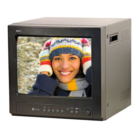
This manual provides installation and operation proce-
dures for the VM615 15-Inch High-Resolution Color
Monitor. The monitor is available in two model variations:
VM615, designed for use with the EIA/NTSC
television system and a 120 V, 60 Hz power
source.
television system and for a 230 V, 50 Hz
power source.
Both models will be referred to as the VM615 in this
manual, unless specified otherwise.
This monitor should only be installed by qualified per-
sonnel using approved materials and practices in con-
formance with federal, state, and local codes. Read these
instructions thoroughly before beginning an installation.
Failure to comply with these instructions may result in
personal injury and/or damage to the equipment.
The VM615 is intended for use in closed-circuit televi-
sion (CCTV) systems. Horizontal resolution is an ex-
tremely high 600 TV lines. Inputs are provided for
standard composite video (NTSC RS-170A or CUR/PAL,
depending on monitor model) and for separate Y/C signals
for playback of S-VHS tapes. Composite or S-VI-IS input
channels are selected with front-panel pushbuttons. The
monitor also features a built-in speaker. Controls include
This monitor should only be installed by qualified per-
sonnel using approved materials and practices in con-
formance with federal, state, and local codes.
WARNING: TO PREVENT RISK OF FIRE OR ELECTRICAL SHOCK, DO NOT EXPOSE THIS UNIT TO RAIN OR MOISTURE.
Product specifications subject to change without notice.
Copyright 0 1997 Vicon Industries Inc. All rights reserved.
TOLL FREE: l-800-645-91 16
1. INTRODUCTION
brightness, contrast, chroma (color saturation), phase
(tint), vertical and horizontal hold, vertical and horizon-
tal position, and vertical size. Refer to Figure 1.
Standard connectors are provided for all signal inputs:
BNC connectors for composite video, miniature four-
pin DIN connector for S-VHS video, and RCA connec-
tors for audio. The monitor is housed in a steel cabinet
with generous provision for air circulation to dissipate
heat. The cabinet is provided with a carrying handle. A
detachable power cord that plugs into a standard IEC
320 power cord connector is supplied. The fuse is housed
in a fuse tray built into the IEC 320 connector for easy
access without having to remove the monitor case.
A looping output connector (BNC) is provided for com-
posite video, along with a switch for selecting 75-ohm
or high-impedance video termination. A looping output
connector (RCA) is also provided for audio.
The VM615 meets FCC requirements for a Class A
device. The VM615-P complies with European Com-
munity EMC Directive 89/336. The product was sub-
jected to the testing outlined in European Normalization
Standard EN 50081-l (Electromagnetic Compatibility
mercial, and Light Industry), and EN 50082-l (Electro-
magnetic Compatibility - Generic Immunity Standard
Part 1: Residential, Commercial, and Light Industry).
2. INSTALLATION
CAUTION:
A
location that provides adequate air circulation
for cooling. Do not blockany of the air circulation
openings in the cabinet.
Vicon and its logo are registered trademarks of Vicon Industries Inc.
UK: 44/(O) 1489/577775
l
All monitors must be installed in a
Vicon part number 8006-8916-00-00
TEL: .516-952~CC-W
FAX: 516-951XCTV
l
l
. INFOFAX: 1-800-287-i 207
Advertisement
Table of Contents

Related Manuals for Vicon VM615


Summary of Contents for Vicon VM615
-
Page 1: Installation And Operation
The cabinet is provided with a carrying handle. A detachable power cord that plugs into a standard IEC Both models will be referred to as the VM615 in this 320 power cord connector is supplied. The fuse is housed manual, unless specified otherwise. -
Page 2: Important Safeguards
6. Attachments - Do not use attachments not recommended by Vicon 16. Overloading - Do not overload wall outlets and extension cords as they may cause hazards. -
Page 3: Fcc Notice
Take all necessary precau- Relocate the equipment away from the receiver. tions to prevent static discharge. 2.1 Unpacking and Inspection All Vicon equipment is inspected and tested before 2.1.2 INSPECTION FOR CONCEALED leaving the factory. It is the carrier’s responsibility to DAMAGE... -
Page 4: Front Panel
FRONT PANEL 1 Main power switch 6 Tint (phase) control (vertical line) is ON; (circle) is OFF. Rotate to obtain the most natural looking colors on the monitor. 2 Composite video channel selector Saturation (chroma) control Push to select the composite video input (input to BNC connector). Rotate to increase or decrease the intensity of colors on the monitor. -
Page 5: Operation
2.2.1.1 Composite Video 2.2.1.3 RGB Video If the video source generates standard EIA/NTSC RS-170A RGB video is input at the g-pin D-shell connector or CClR/PAL color or monochrome video, connect acoaxial (Figure 1, item 17). The mating connector must be wired according to Figure 3. -
Page 6: Maintenance
4. MAINTENANCE a damp cloth from time to time to remove dust. Do not The VM615 monitor does not require scheduled main- spray a glass cleaner directly on the screen. 4.1 Fuse Replacement 2. - Page 7 5. REFERENCE COAXIAL CABLE RECOMMENDATIONS The shield must be copper braid providing 95% or better CAUTION: Careful selection of the proper cable is essen- coverage. Installation Tips when cables other than those recommended are in- Do not stretch cable or subject it to sharp bends. stalled.
- Page 8 (R.A.) at one of the locations listed below. Record the unit the name of the Vicon employee who issued the R.A. b . Name of the Vicon employee who issued the R.A. VICON INDUSTRIES INC. c. R.A. number 89 Arkay Drive...
Need help?
Do you have a question about the VM615 and is the answer not in the manual?
Questions and answers