Table of Contents
Advertisement
Quick Links
Installation and Operation Guide
XX-223-10-00
VM-610LCD
Flat Panel LCD Monitor
Vicon Industries Inc., 89 Arkay Drive, Hauppauge, New York 11788
Tel: 631-952-CCTV (2288) Fax: 631-951-CCT (2288) Toll Free: 800-645-9116
24-Hour Technical Support: 800-34-VICON (800-348-4266) UK: 44/(0) 1489-566300
Vicon Industries Inc. does not warrant that the functions contained in this equipment will meet your requirements or that the
operation will be entirely error free or perform precisely as described in the documentation. This system has not been designed
to be used in life-critical situations and must not be used for this purpose.
www.vicon-security.com
Document Number: 8009-8223-10-00
Issued: 1110
Product specifications subject to change without notice.
Copyright © 2010 Vicon Industries Inc. All rights reserved.
Advertisement
Table of Contents

Related Manuals for Vicon VM-610LCD


Summary of Contents for Vicon VM-610LCD
- Page 1 24-Hour Technical Support: 800-34-VICON (800-348-4266) UK: 44/(0) 1489-566300 Vicon Industries Inc. does not warrant that the functions contained in this equipment will meet your requirements or that the operation will be entirely error free or perform precisely as described in the documentation. This system has not been designed to be used in life-critical situations and must not be used for this purpose.
- Page 3 SAFETY INSTRUCTION ………………………………………………………………….. 2 ~ 3 CAUTIONS ………………………………………………………………......4 ~ 5 FCC RF INTERFERENCE STATEMENT ……………………………......CONNECTING WITH EXTERNAL EQUIPMENT ………………………………………. CONTROLS AND FUNCTIONS ………………………………………………………….. 8 ~ 25 MOUNTING GUIDE ……………………………………………………………………….. 26 ~ 27 D-SUB CONNECTOR PIN ASSIGNMENTS ……………………………………………. POWER MANAGEMENT …………………………………………………………………. SPECIFICATIONS ………………………………………………………………………….
-
Page 4: Important Safeguards - Indoor Use
Important Safeguards – Indoor Use GRAPHIC SYMBOL EXPLANATION 12. Lightning - Disconnect the product from its power source and The lightening bolt symbol alerts the user to the presence of cable system when possible to prevent damage due to lightning dangerous voltage that may present the risk of electric shock. - Page 5 Important Safeguards – Indoor Use (Cont) 22. For Rack-Mounted Units Only – The following precautions apply to all rack-mounted units. Elevated Operating Ambient - If installed in a closed or multi- unit rack assembly, the operating ambient temperature of the rack environment may be greater than room ambient.
-
Page 6: Instruction Manual
CAUTION The power supply cord is used as the main disconnect device, ensure that the socket-outlet is located/installed near the equipment and is easily accessible. ATTENTIONN Le cordon d`alimentation est utillsé comme interrupteur général. La prise de courant doit être située ou installée à... - Page 7 "Rack Mount Instructions - The following or similar rack-mount instructions are included with the installation instructions: A) Elevated Operating Ambient - If installed in a closed or multi-unit rack assembly, the operating ambient temperature of the rack environment may be greater than room ambient. Therefore, consideration should be given to installing the equipment in an environment compatible with the maximum ambient temperature (Tma) specified by the manufacturer.
-
Page 8: Fcc Notice
FCC Notice Note: Complies with Federal Communications Commission Rules & Regulations Part 15, Subpart B for a Class A digital device. WARNING This equipment generates and uses radio frequency energy and if not installed and used properly, that is, in strict accordance with the manufacturer’s instruction, may cause interference to radio and television reception. -
Page 9: Trigger Input
A. BACK 1. TRIGGER INPUT Sensor Signal Input 2. AUDIO IN 3.5Φ STEREO IN 3. S-VIDEO IN Y/C separated signal input 4. AV1 IN Composite signal Input for AV1 5. AV1 OUT Video looping output for AV1 6. AV2 IN Composite signal Input for AV2 7. -
Page 10: Power On/Off
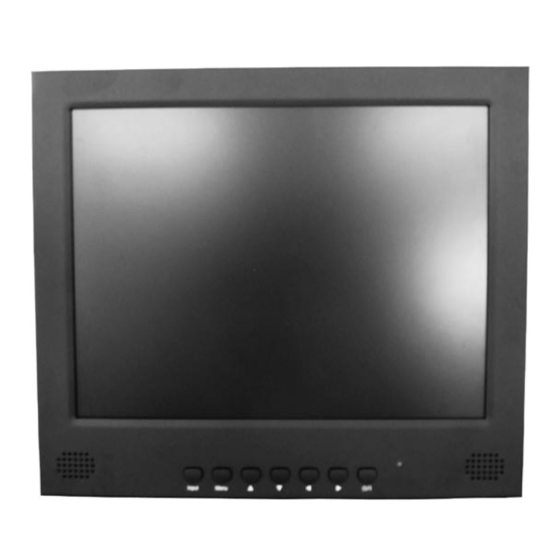
B. FRONT 1. INPUT Select input source. 2. MENU Activates and exits the On Screen Display. This button can also be used to move previous menu or status. OSD MENU(MAIN) : Input Source, Screen, Audio, OSD, Color, Utility, Exit. 3/4. ▲ / ▼ This button allows user to enter the sub-menu of the activated function ▼... - Page 11 OSD Menu Description of This Monitor A: CUSTOM MENU (For AV1, AV2 & S-Video Input) 1) Press the MENU button and then press the up(▲) or down(▼) button to select the Custom. 2) Press the up(▲) or down(▼) button to select the sub menu. 3) Press the left(◀) or right(▶) button to adjust the picture setting.
-
Page 12: Picture Mode
B. Picture / Sound Menu (For AV1, AV2 & S-Video) 1. Picture Mode 1) Press the MENU button and then press the up(▲) or down(▼) button to select the Picture / Sound. 2) Press the right(▶) or INPUT button. 3) Press the up(▲) or down(▼) button to select the Picture Mode. 4) Press the right(▶) or INPUT button. - Page 13 3. Mute 1) Press the up(▲) or down(▼) button to select the Mute. 2) Press the right(▶) or INPUT button. 3) Press the up(▲) or down(▼) button to select the On or Off. 4) Press the MENU button to save. 4.
- Page 14 5. Size 1) Press the up(▲) or down(▼) button to select the Size 2) Press the right(▶) or INPUT button. 3) Press the up(▲) or down(▼) button to select the Size option. 4) Press the MENU button to save. 6. NR 1) Press the up(▲) or down(▼) button to select the NR.
- Page 15 7. 3D Comb 1) Press the up(▲) or down(▼) button to select the 3D Comb. 2) Press the right(▶) or INPUT button. 3) Press the up(▲) or down(▼) button to select the On or Off. 4) Press the MENU button to save. 8.
- Page 16 B. Picture / Sound Menu (For PC Input) 1. Picture Mode 1) Press the MENU button and then press the up(▲) or down(▼) button to select the Picture/Sound. 2) Press the right(▶) or INPUT button. 3) Press the up(▲) or down(▼) button to select the Picture Mode. 4) Press the right(▶) or INPUT button.
- Page 17 3) Press the left(▶) or INPUT button again. 4) Press the up(▲) or down(▼) button to select the Color Tone option. 5) Press the MENU button to save. 2-2. Color Tone (Custom) 1) Press the up(▲) or down(▼) button to select the Custom in the Color Tone. 2) Press the Menu button to save.
- Page 18 3) Press the up(▲) or down(▼) button to select the Red(R), Green(G) or Blue(B). 4) Press the left(◀) or right(▶) button to adjust color density. 5) Press the MENU button to save. Input 4. PC control (Only PC 1) Press the up(▲) or down(▼) button to select the PC. 2) Press the right(▶) or INPUT button.
-
Page 19: Setup Menu
C. SETUP MENU 1) Press the MENU button and then press the up(▲) or down(▼) button to select the Setup. 1. Reset 1) Press the right(▶) or INPUT button 2) Press the right(▶) or INPUT button again. 3) Press INPUT button to execute the reset. Reset: All settings go to the factory initialization. - Page 20 2. Language 1) Press the up(▲) or down(▼) button to select the Language. 2) Press the right(▶) or INPUT button. 3) Press the up(▲) or down(▼) button to select language. 4) Press the MENU button to save. 3. OSD Tone 1) Press the up(▲) or down(▼) button to select the OSD Tone.
- Page 21 4. Blue Screen 1) Press the up(▲) or down(▼) button to select the Blue Screen. 2) Press the right(▶) or INPUT button. 3) Press the up(▲) or down(▼) button to select the On or Off. 4) Press the MENU button to save. 5.
-
Page 22: Trigger Enable
6. Trigger 1) Press the up(▲) or down(▼) button to select the Trigger. 2) Press the right(▶) or INPUT button. 6-1. Trigger Enable 1) Press the up(▲) or down(▼) button to select the Trigger Enable. 2) Press the right(▶) or INPUT button. 3) Press the up(▲) or down(▼) button to select the On or Off. - Page 23 6-2. Trigger Input 1) Press the up(▲) or down(▼) button to select the Trigger Input . 2) Press the right(▶) or INPUT button. 3) Press the up(▲) or down(▼) button to select the Trigger Input option. 4) Press the Menu button to save. 6-3.
- Page 24 6-4. Trigger Time 1) Press the up(▲) or down(▼) button to select the Trigger Time. 2) Press left( ) ◀ or right(▶) button to adjust Trigger Time setting. 3) Press the MENU button to save. 6-5 Trigger Option 1) Press the up(▲) or down(▼) button to select the Trigger Option. 2) Press the right(▶) or INPUT button.
-
Page 25: Auto Switching
7. Auto switching 1) Press the up(▲) or down(▼) button to select the Auto switching. 2) Press the right(▶) or INPUT button. 7-1. Auto switching On/Off 1) Press the right(▶) or INPUT button. 3) Press the up(▲) or down(▼) button to select the On or Off . 4) Press the Menu button to save. - Page 26 7-2. Auto switching Inputs enabled 1) Press the up(▲)or down(▼) button to select the Inputs enabled. 2) Press the right(▶) or INPUT button. 3) Press the up(▲) or down(▼) button to select the Input. 4) Press the right(▶) or INPUT button. 5) Press the up(▲) or down(▼) button to select the On or Off and then press the Menu button to save.
- Page 27 7-3. Auto switching Time 1) Press the up(▲) or down(▼) button to select the Time. 2) Press the left(◀) or right(▶) button to adjust the Time and then press the MENU button to save. INSTRUCTION MANUAL ……………………………………………………………………. 25...
- Page 28 A. Wall mount(Optional) 1) Using the 75 mm VESA holes. 2) Using the VESA standard wall mount design and the 75mm hole pattern on the back side to install the LCD monitor to the wall. TRIGGER TRIGGER TRIGGER TRIGGER TRIGGER TRIGGER INPUT INPUT...
- Page 29 B. Rack mount(Optional) 1) Install the monitor in the Pre-Rack using the 75 mm VESA holes. 2) Install the Pre-Rack in the Open Rack using side mounting holes. ※ The Pre-Rack is available rotation of 360° on the Open Rack. INSTRUCTION MANUAL …………………………………………………………………….
- Page 30 ▶ PIN ASSIGNMENTS Pin 1 RED VIDEO GREEN VIDEO SIGNAL CABLE DETECT BLUE VIDEO GROUND GROUND SDA(for DDC) GROUND H-SYNC.(or H+V SYNC.) RED GROUND V-SYNC. GREEN GROUND SCL(for DDC) BLUE GROUND ACCESSORY ▶ 1. Power cord 2. User’s manual 3. PC cable 4.
-
Page 31: Power Consumption
This monitor features a power management system to “power down” upon receipt of the VESA DPMS(The display power management signaling) from a VESA DPMS video card. The VESA DPMS-compliant video card performs this signaling system through not sending horizontal, vertical, or sync signal. This monitor enters an appropriate mode through identifying each of the three modes of the signaling system. - Page 32 10.4” 10.4˝ Diagonal AM-TFT(Active-Matrix) Pixel pitch(mm) : 0.264(H) x 0.264(V) BRIGHTNESS: 300cd/㎡(Typical) LCD-Type CONTRAST RATIO: 500:1(Typical) VIEWING ANGLE: 150°/110°(H/V) RESPONSE TIME: 30msec(Typical) RESOLUTION (H x V) 800X600@60Hz FREQUENCY HORIZONTAL: 37.5kHz, VERTICAL: 60Hz VIDEO(2ch input 1.0Vp-p, 75Ω terminated, loop-through out) S-VIDEO(1ch input (Y/C)) INPUT SIGNAL PC RGB PC Stereo In...
-
Page 33: Weee Symbols
WEEE Symbols Correct Disposal of This Product (Waste Electrical & Electronic Equipment) (Applicable in the European Union and other European countries with separate collection systems) This marking shown on the product or its literature, indicates that it should not be disposed with other household wastes at the end of its working life. - Page 34 MEMO...
- Page 35 Vicon Standard Equipment Warranty Vicon Industries Inc. (the “Company”) warrants your equipment to be free from defects in material and workmanship under Normal Use from the date of original retail purchase for a period of three years, with the following exceptions: VCRs, all models: Labor and video heads warranted for 120 days from date of original retail purchase.
- Page 36 Vicon Industries Inc. Corporate Headquarters 89 Arkay Drive Hauppauge, New York 11788 631-952-CCTV (2288) 800-645-9116 Fax: 631-951-CCTV (2288) Vicon Europe Headquarters Brunel Way Fareham, PO15 5TX United Kingdom +44 (0) 1489 566300 Fax: +44 (0) 1489 566322 Vicon Germany Kornstieg 3...
Need help?
Do you have a question about the VM-610LCD and is the answer not in the manual?
Questions and answers