Table of Contents
Advertisement
Quick Links
Advertisement
Table of Contents

Related Manuals for StarTech.com 1UCABCONS


Summary of Contents for StarTech.com 1UCABCONS
- Page 1 Cabinet Console 1UCABCONS 1UCABCONS17 1UCABCONS19...
- Page 2 Where they occur these references are for illustrative purposes only and do not represent an endorsement of a product or service by StarTech.com, or an endorsement of the product(s) to which this manual applies by the third-party company in question. Regardless of any direct acknowledgement elsewhere in the body of this document, StarTech.com hereby acknowl-...
-
Page 3: Table Of Contents
Instruction Manual Instruction Manual Table of Contents Introduction ................... 1 System requirements ..............2 Assembly ..................5 Installation ..................10 Connecting to a USB Controlled Computer .........10 Connecting to a PS2 Controlled Computer .........11 Connecting to a KVM Switch ............11 Operation .................. -
Page 4: Introduction
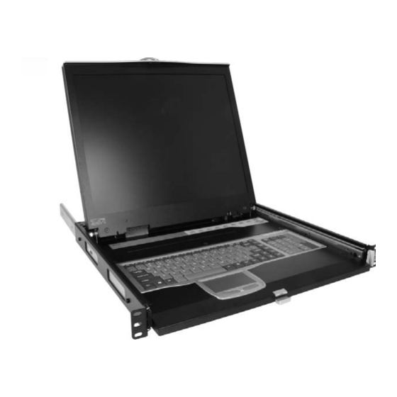
Instruction Manual Introduction Thank you for purchasing a StarTech.com 1U Cabinet Console. This console offers the ultimate in computer management, especially for applications where space is at a premium. The console drawer can be pulled out from the rack for operation, on sliding rails that latch in the extended position;... -
Page 5: System Requirements
Note: the following length is measured between front and rear poles, inside the rack cabinet not the outside depth of a rack Front pole to rear pole distance 1UCABCONS 1UCABCONS17 1UCABCONS19 ( Depth ) inch... - Page 6 Instruction Manual Overhead Diagram KVM Module KVM Module Console Console Drawer Drawer The KVM Module can be connected to a console, or be used as a stand- alone KVM Switch. There are three major categories: PS/2, USB and Sun Interfaces: Type PS/2 KVM Model name...
- Page 7 Instruction Manual Type Hybrid KVM Model name CAB831HD CAB1631HD Interface PS/2, USB No. of Console Ports No. of Computer Ports OSD Menu Height Cable Type PS2 – SVECONx USB - SVECONUSx Type IP KVM Model name CAB1641HDI Interface PS/2, USB No.
-
Page 8: Assembly
Instruction Manual Assembly 1. Choose a proper position for the rack drawer. Mount the rear brackets (from the Rear bracket & extension kit) and lightly fasten them onto the rear vertical poles. Both will be removed later. 2. Remove the safety stopper from the console drawer. The safety stopper is designed to prevent the drawer from sliding out during transportation. - Page 9 Instruction Manual 3. Slide the assembled drawer into the rack cabinet from the front and insert the two slide rails of the assembled drawer into the pockets of the rear brackets. 4. Fasten the assembled drawer onto the front brackets using the four screws provided.
- Page 10 Instruction Manual 6. Attach the extensions (from the Rear bracket & extension kit) to both sides of the KVM switch module. Please note the length of the extensions and mount them as shown. For a 2U module, the extensions are mounted to the lower half of the module. NOTE: the orientation of the wide side of the extension 7.
- Page 11 Instruction Manual 8. Push the KVM switch module evenly toward the drawer: 9. Slide the console drawer out and fasten both units together using the screws provided:...
- Page 12 Instruction Manual 10. Make sure the C-36 connectors are firmly connected: 8mm (5/16”) C36 Connector 11. Connect the power supply to the power jack on the KVM module to complete the assembly.
-
Page 13: Installation
USB port not both simultaneously. Connecting to a USB Controlled Computer Connect the standard VGA cable and a USB A-B cable to the computer and 1UCABCONS as shown below. The computer can be a USB-ready PC, Sun, HP server, or a Mac. Male-to-Female... -
Page 14: Connecting To A Ps2 Controlled Computer
Connecting to a PS2 Controlled Computer Connect the standard VGA cable and two mini-DIN6 male-to-male cables to the computer and 1UCABCONS as shown below. There are two mini- DIN6 female connectors marked with keyboard and mouse, be sure not to swap the connections. -
Page 15: Operation
Instruction Manual Operation Front Panel Functions KVM Control and Status: (This section is effective only when a KVM switch module is connected.) 1. Computer Selection Pad - Press one of these pushbuttons to select a computer. For 16 port models, 1-8 represent the lower 8 ports, while A-H indicates the higher 8 ports. -
Page 16: Keyboard Replacement
Instruction Manual Keyboard Status and LCD Panel Power Switch: 7. Num Lock - Keyboard Num Lock status 8. Caps Lock - Keyboard Caps Lock status 9. Scroll Lock - Keyboard Scroll Lock status 10. LCD Panel Power Switch Keyboard Replacement The keyboard is replaceable, in the event of language changes or maintenance. -
Page 17: Touchpad Replacement
Instruction Manual Touchpad Replacement The built-on Touchpad offers “wheel mouse” functionality. The area of the Touch Pad to the right side of the two small triangular marks is the simulated “wheel” as shown below: Triangular Marker Scroll Wheel Area Left Mouse Button Right Mouse Button To remove the Touch Pad, press the tab underneath it upward to release the latch, then slide it outwards until the Touch Pad can be lifted up clear from the notches, as shown in the figure below (right side). -
Page 18: Specifications
Instruction Manual Specifications 1UCABCONS 1UCABCONS17 1UCABCONS19 304.1 x 376.32 x Active Display 337.920 x Area (mm) 270.336 228.1 301.056 0.297(H) x 0.264 (H) x 0.294(H) x Pixel Pitch (mm) 0.297(V) 0.264 (V) 0.294(V) 1024 x 768 1280 x 1024 Resolution... - Page 19 Instruction Manual 2 CCFLs 4 CCFLs edge-light Backlight Unit edge-light (top/bottom) (top/bottom) Operating 0 to +50 (°C) Temperature Storage -20 to +60 (°C) Temperature Operating Relative Humidity 8% ~ 95% Humidity Non-Operating 95% RH Humidity Power Supply Full range, 100V AC to 240V AC Input Voltage Regulatory CE, FCC for the product.
-
Page 20: Technical Support
Limitation of Liability In no event shall the liability of StarTech.com Ltd. and StarTech.com USA LLP (or their officers, directors, employees or agents) for any damages (whether direct or indirect, special, punitive, incidental, consequential, or otherwise), loss of profits, loss of business, or any pecuniary loss, arising out of or related to the use of the product exceed the actual price paid for the product. - Page 21 Cable Finder, Parts Finder and the KVM Reference Guide. StarTech.com makes it easy to complete almost any IT or A/V solution. Find out for yourself why our products lead the industry...
Need help?
Do you have a question about the 1UCABCONS and is the answer not in the manual?
Questions and answers