
Related Manuals for StarTech.com SAT3550ESR


Summary of Contents for StarTech.com SAT3550ESR
- Page 1 SATA RAID Drive Enclosure 5 Drive 3.5” eSATA to SATA RAID Drive Enclosure SAT3550ESR Instruction Manual Actual product may vary from photo...
- Page 2 StarTech.com. Where they occur these references are for illustrative purposes only and do not represent an endorsement of a product or service by StarTech.com, or an endorsement of the product(s) to which this manual applies by the third-party company in question.
-
Page 3: Table Of Contents
Partition Configured Volumes ......18 Administering the SAT3550ESR Drive Enclosure .....20 Configuring the SAFE Volume Rebuild Storage Policy . -
Page 4: Introduction
I I n n t t r r o o d d u u c c t t i i o o n n Thank you for purchasing a StarTech.com 5 Drive 3.5” eSATA to SATA RAID Drive Enclosure. A cost-effective storage solution, SAT3550ESR provides enhanced data protection, high-performance storage and plug-and-play functionality, making it a simple solution for professional or home users to replicate data and maintain data security. -
Page 5: Host Controller Installation
In order to provide a software and hardware link between the host computer and the SAT3550ESR Drive Enclosure, it is required that the included PCI Express Host Controller be installed on the host computer. You may also use another Host Controller, provided it features port multiplier support, however it is not guaranteed that all host controllers with port multiplier support are compatible with the drive enclosure. -
Page 6: Hardware Guide
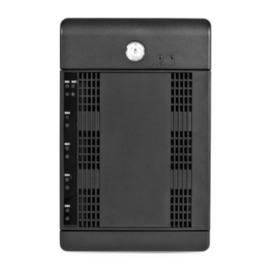
Instruction Manual Hardware Guide Front Panel (closed) Rear Panel Power Power Port Button eSATA port Front Panel (open) Error Condition Indicator OK Indicator Drive Bays Key Lock Safety latch Front Panel Door... -
Page 7: Hard Drive Installation
1/4 turn in a clockwise direction. Connecting the Drive Enclosure to the computer To connect the SAT3550ESR Drive Enclosure to the host computer : Connect one end of a standard eSATA cable to the port located on the rear panel of the Drive Enclosure;... -
Page 8: Configuration
Instruction Manual C C o o n n f f i i g g u u r r a a t t i i o o n n Introduction Windows 1. Click on the Start button, and select All Programs. Click on Sil 4726 Manager to launch the configuration program. -
Page 9: Status Window
Capacity Information Elements of the Status window System Status section Temp : Indicates the current internal temperature of the SAT3550ESR Drive Enclosure Fan Speed : Indicates the system fan status. Use this data to monitor possible malfunctions Drive Status section... - Page 10 Instruction Manual Capacity Information section Policy : Shows the storage policy configured for each volume. Total : Shows the combined capacity of the volume. Drive # : Shows capacity information for each hard disk . Capacity : Shows the full amount of storage space (in GB) available on each hard disk. Volume : Shows the total volume capacity and the drive capacities assigned to each volume.
-
Page 11: Basic Configuration
The Wizard defines volumes based on a selected storage policy. An end-user cannot modify volume counts or capacities. To protect against unintentional changes, the SAT3550ESR prompts for a password for first time access of the Wizard. The default password is admin. (For additional information on the default password, please see the section entitled Change Password.) - Page 12 Instruction Manual Write configuration from system to a file Saves a configuration to a file on the host computer. Restore configuration to last commit Cancels proposed changes Command buttons on the Basic Configuration Wizard To Advanced Mode : Opens the Advanced Configuration Wizard Apply : Submits configuration changes to the Drive Enclosure, and closes the Configuration Wizard.
- Page 13 Instruction Manual ***Basic Storage Policy Options: JBOD (bypass) : Creates a logical volume for each physical hard disk. SAFE (RAID 1) : Creates two volumes. For each volume, one hard disk is mirrored onto a second drive. Makes the remaining drive the Hot Spare for both volumes.
-
Page 14: Advanced Configuration
A A d d v v a a n n c c e e d d C C o o n n f f i i g g u u r r a a t t i i o o n n The following section details how to use the Advanced Configuration Wizard to apply more than one storage policy to volumes in the SAT3550ESR Drive Enclosure. While the Basic Configuration provides six predefined storage policies to quickly configure the Drive Enclosure, the Advanced Configuration Wizard allows you to configure up to ten volumes, each with different storage policies and capacities. - Page 15 Delete selected volume volume list. Deletes all configured volumes. Delete all volumes Copy configuration Copies the configuration of another SAT3550ESR to the from other device in the current SAT3550ESR. system Command buttons on the Advanced Configuration Wizard To Basic Mode : Opens the Basic Configuration Wizard.
-
Page 16: Multiple Volume Configuration
The same sequence of steps applies to any configuration you choose to implement; only the storage policy and capacity allocation vary for different configuration options. NOTE: Before reconfiguring an existing SAT3550ESR Drive Enclosure with a new configuration, backup the data. Use the Disk Management utility provided by your OS to delete all partitions - except the unallocated, un-initialized disk that represents the SteelVine processor. - Page 17 Instruction Manual Select SAFE (RAID1) as the Storage Policy. Click on the Use check boxes underneath Drives 0 and 1. Move the slide to 50. Safe Mode Uncheck Hot Spare Move Slider 7. Click Update Volume. 8. When prompted whether to create a Hot Spare for the SAFE volume, click No. In some configurations, you may want the added redundancy of a Hot Spare.
- Page 18 Instruction Manual 12. Move the slider beneath Drive 0 all the way to the right to allocate the remaining capacity on the two drives to the FAST volume. If you wish, you can allocate less than the total remaining capacity to the new volume. However, doing so makes the unallocated capacity unavailable and unused.
-
Page 19: Manage Configuration Files
(storage policy). The Save to Config File command from the File menu in the Basic Configuration Wizard exports an SAT3550ESR Drive Enclosure configuration to a file. Each of the procedures in the Basic Configuration chapter prompts you to save a configuration file. - Page 20 Instruction Manual Save a Configuration File 1. Select Configure Box from the Edit menu or click the Configure Box toolbar button in the Status window to open the Basic Configuration Wizard. 2. Select Save to Config File from the File menu in the Basic Configuration Wizard. 3.
-
Page 21: Partition Configured Volumes
Instruction Manual P P a a r r t t i i t t i i o o n n C C o o n n f f i i g g u u r r e e d d V V o o l l u u m m e e s s This chapter explains how to partition volumes after configuring them with the SiI 4726 Manager software. - Page 22 Instruction Manual 7. Assign a drive letter or mount path and click Next. 8. Select the appropriate file system, name the partition and click Next. 9. Review the file system settings and click Finish to create the logical partition. 10. Repeat steps 1 through 9 to partition any remaining disks you configured in the SiI 4726 Manager software.
-
Page 23: Administering The Sat3550Esr Drive Enclosure
Instruction Manual 8. You will receive a warning that “ Partitioning a disk will destroy all information on the disk ”. Click Partition to acknowledge the warning. Disk Utility mounts the created partition and represents it with an icon on the desktop. The icon is labeled with the partition name. -
Page 24: Configuring The Safe Volume Rebuild Storage Policy
Instruction Manual Set up a remote connection Before a remote connection can be established, the following conditions must be true: • The Daemon is installed and running on a host computer connected to the Drive Enclosure • The user interface is installed and running on a remote host computer. •... -
Page 25: Email Notification
Instruction Manual Enclosure are actively monitored, the Automatic Rebuild should be set up to minimize the possibility of data loss. Please Note: In case No is selected in response to a rebuild prompt, select Scan Devices from the File menu of the Status window to trigger a new prompt. Please Note: Once the Daemon rebuilds to a designated Hot Spare, a designated Hot Spare will not exist. - Page 26 Instruction Manual Setup E-mail Notification Setting-up Email Notification 1. The box available for the SMTP Server Name can be left blank. The SiI 4726 Manager software will perform a DNS lookup and automatically find the correct address. 2. The box available for the SMTP Server Port# uses Port 25 as a default. 3.
-
Page 27: Install New Firmware & Software
1. Click the Specify Firmware toolbar button or select Specify Firmware from the Edit menu of the Status window. The Firmware Selection dialog displays all of the SAT3550ESR Drive Enclosures attached to the host, the integrated circuit (IC) revision, and the current firmware installed on each Drive Enclosure (assuming more than one SAT550ESR is in use). -
Page 28: Editing The Userconfig.xml
Instruction Manual 5. Click OK to dismiss a message box that states the firmware was successfully downloaded. Editing the UserConfig.xml The UserConfig.xml file is used to define the Status Screen Title Bar and allow configuration of the Policy Change as well as the Advanced Configuration features. The UserConfig.xml file can be found in the following location: C:\Program Files\SiI4726\SiI 4726 Manager\SiI 4726 Config To edit this file, Right Click on the file name, select Open With, and select Notepad. - Page 29 Instruction Manual The ‘AllowAdvancedConfig’–True–turns on the Advanced Config feature. If the end- user changes the XML tag value to False, the general Configure feature will still be available, but the Advanced button (inside the Configuration feature) will not be available: <AllowAdvancedConfig>False </AllowAdvancedConfig>...
-
Page 30: Monitoring And Troubleshooting
Instruction Manual M M o o n n i i t t o o r r i i n n g g a a n n d d T T r r o o u u b b l l e e s s h h o o o o t t i i n n g g Monitoring drive status The color of the drives in the Status window indicates the status of the hard disk drives: Color... - Page 31 Instruction Manual Monitoring fan status Color Value Description Resoluti Both system and power supply fans Green System + PS are functioning within limits. The system fan is not spinning or System spinning is slower than expected. The power supply fan is not spinning Repair spinning slower required.
- Page 32 LED 0 LED 1 When SAT3550ESR is powered on, the host scans the disks in sequence, as indicated by a brief flash of lights on LED 1. Once the host scan is complete, LED 1 is lit for each drive present. During disk operations, LED 0 flashes as data is transferred to and from the drive and the host.
- Page 33 Instruction Manual Status Indicators for ! and OK LEDs Description Startup or ON indication. OK LED will flash during reset and will remain green in all other cases. ERROR. The‘!’LED will light as a result of an EEPROM error during boot or following a runtime error.
-
Page 34: Storage Policies Glossary
S S t t o o r r a a g g e e P P o o l l i i c c i i e e s s G G l l o o s s s s a a r r y y SAT3550ESR provides the following storage policies, for mapping physical to virtual drives. - Page 35 Instruction Manual A storage policy in which one-half of the available storage space is concatenated, while the other half mirrors the first half to provide full data redundancy. SAFE and BIG In the SAFE and BIG storage policy, the Basic Configuration Wizard mirrors the concatenated disks to create a volume consisting of four disk drives, designating the remaining hard disk drive as a Hot Spare.
-
Page 36: Specifications
Limitation of Liability In no event shall the liability of StarTech.com Ltd. and StarTech.com USA LLP (or their officers, directors, employees or agents) for any damages (whether direct or indirect,... - Page 37 Visit www.startech.com for complete information about all our products and to access exclusive interactive tools such as the Parts Finder and the KVM Reference Guide. StarTech.com makes it easy to complete almost any IT solution. Find out for yourself why our products lead the industry in performance, support, and value.
Need help?
Do you have a question about the SAT3550ESR and is the answer not in the manual?
Questions and answers