Table of Contents
Advertisement
WARNING: Antenna Pedestal must be properly restrained (stowed) to
prevent damage to wire rope isolators, isolator springs and/or antenna pedestal
mechanism during underway conditions when power is removed from the
antenna assembly.
Sea Tel, Inc.
4030 Nelson Avenue
Concord, CA 94520
Tel: (925) 798-7979
Fax: (925) 798-7986
Email: seatel@cobham.com
Web: www.cobham.com\seatel
April 23, 2009
INSTALLATION AND OPERATION MANUAL
FOR SEA TEL MODEL
DTV04 HD 5LNB TVRO ANTENNA
Sea Tel Inc doing business as Cobham SATCOM
Sea Tel Europe
Unit 1, Orion Industrial Centre
Wide Lane, Swaythling
Southampton, UK S0 18 2HJ
Tel: 44 (0)23 80 671155
Fax: 44 (0)23 80 671166
Email: seatel@cobham.com
Web: www.cobham.com\seatel
Document. No. 130099 Revision A
Advertisement
Table of Contents
Troubleshooting

Subscribe to Our Youtube Channel
Related Manuals for Sea Tel DTV04


Summary of Contents for Sea Tel DTV04
- Page 1 Southampton, UK S0 18 2HJ Fax: (925) 798-7986 Tel: 44 (0)23 80 671155 Email: seatel@cobham.com Fax: 44 (0)23 80 671166 Web: www.cobham.com\seatel Email: seatel@cobham.com Web: www.cobham.com\seatel Sea Tel Inc doing business as Cobham SATCOM April 23, 2009 Document. No. 130099 Revision A...
- Page 2 All Rights Reserved. The information contained in this document is proprietary to Sea Tel, Inc.. This document may not be reproduced or distributed in any form without the consent of Sea Tel, Inc. The information in this document is subject to change without notice.
- Page 4 Revision History ECO# Date Description April 23, 2009 Initial Release...
-
Page 5: Table Of Contents
DTV04 HD TVRO Antenna Table of Contents 1. INTRODUCTION ................................... 1-1 1.1. G ............................1-1 ENERAL ESCRIPTION OF SYSTEM 1.2. G ............................1-2 ENERAL SCOPE OF THIS MANUAL 1.3. Q ............................1-2 UICK VERVIEW OF CONTENTS 2. OPERATION ...................................... 2-1 2.1. - Page 6 Table of Contents DTV04 HD TVRO Antenna 4.8. P – O ..........................4-3 OWER BSERVE THE NTENNA 4.9. S ......................................4-3 ETUP 5. SETUP ........................................5-1 5.1. I .................................... 5-1 NITIAL ETUP 5.2. D – DTV04 HD A ................5-1...
-
Page 7: Introduction
This input will be distributed to all of your satellite TV receivers which will provide the Audio/Video to your televisions. The DTV04 HD system is a fully stabilized antenna that has been designed and manufactured so as to be inherently reliable, easy to maintain, and simple to operate. Except for start-ups, or when changing to operate with different transponders, the equipment essentially permits unattended operation. -
Page 8: General Scope Of This Manual
1.2. General scope of this manual This manual describes the Sea Tel Model DTV04 HD Antenna (also called the Above Decks Equipment), its operation and installation. The Below Decks Equipment is described in the manuals provided with your DAC-2202 Antenna Control Unit 1.3. -
Page 9: Operation
DTV04 HD TVRO Antenna Operation Operation Operation of your system is accomplished from the Antenna Control Unit (ACU). Please refer to the operation section of the DAC-2202 Antenna Control Unit manual. 2.1. System Power-up Turn ON the power switch on the front panel of the ACU. The DTV 04 HD Antenna receives its DC power from the Antenna Control Unit (ACU) when the ACU is energized. -
Page 10: Tracking Operation
Tracking Operation The design of this system allows for simultaneous reception of 5 satellites, 3 at Ku-Band and 2 at Ka-Band. For the DTV04 HD Antenna system all tracking parameter entries are based on signal level received from 101°W. Tracking optimizes the antenna pointing, in very fine step increments, to maximize the level of the satellite signal being received. -
Page 11: Basic System Information
Your DTV04 HD antenna is designed to be used with DIRECTV Satellites that operate at both the Ku-Band (12.2-12.7GHz) and Ka-Band (18.3 – 18.8GHz and 19.7 – 20.2GHz) in this orbit that have a strong enough receive signal level in your location. - Page 12 Basic System Information DTV04 HD TVRO Antenna Blockage - Blockage is loss due to an object in the path of the signal from the satellite to the dish. If an object that is large and dense is positioned in the path of the signal from the satellite, it will prevent sufficient signal from arriving at the dish.
-
Page 13: Signal Level
Satellites may transmit their signals in one of two different polarization modes, linear (like a flat ribbon down from the satellite) or circular (like a twisted ribbon spiraling down from the satellite). The DTV04 HD antennas are designed to receive circular satellite signals only. 3.2. Antenna Basics Figure 3-5 Satellite Signal Polarization The satellite dish is mounted on a three jointed pedestal. -
Page 14: Antenna Reflector/Feed Assembly
Stabilization Reflector/Feed Assembly The DTV04 HD antennas are stabilized in three axes of motion. Stabilization is the process of de- coupling the ships motion from the antenna. Simply put, this allows the antenna to remain pointed at the satellite while the boat turns, rolls or pitches under it. To accomplish this, the Pedestal Control Unit (PCU) on the antenna pedestal senses any motion of the antenna and immediately applies drive to the appropriate motor (s) to oppose the sensed motion. -
Page 15: Tracking
3.2.7. Tracking The DTV04 HD antenna actively optimizes the pointing of the dish for maximum signal reception. This process is called tracking and is accomplished by continuously making small movements of the dish while monitoring the level of the received signal from DIRECTV at 101°W. Evaluation of this information is used to continuously make minor pointing corrections to keep the signal level “peaked”... -
Page 16: Components Of The
The DTV04 04 Antenna system is comprised of two major sections: The Above-Decks Equipment (ADE) is comprised solely of the DTV04 HD antenna radome assembly which is mounted outside, on the boats upper deck or mast location. The Below-Decks Equipment (BDE) includes the Antenna Control Unit, may include the optional Touch Screen Controller panel, satellite receiver(s), TV set(s) and all other ancillary equipment that is mounted in various locations throughout the interior of the boat. -
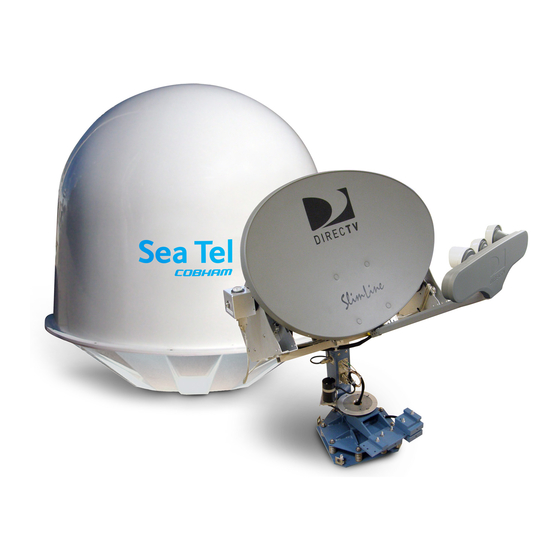
Page 17: Antenna Ade Assembly
Frequencies, 250-750MHz and 1650- 2150MHz for Ka-Band Converted Frequencies) signals from the antenna Figure 3-9 DTV04 HD Above Decks Equipment assembly directly to the DIRECTV 5LNB compatible active matrix switch as well as the DC Voltage & Tone switching from the Matrix Switch to the LNB. -
Page 18: Power Supply
DAC2202. Multiswitch’s are available at the time of purchase from Sea Tel for 12 outputs (SMS 41209 WBP Sea Tel P/N 130010-1) for support of up to 11 receivers and 16 outputs (SMS 41609 WBP Sea Tel P/N 130010-2) for support of up to 15... -
Page 19: Installation
The following instructions describe the installation procedures for installing the Series 04 Antenna (ADE). 4.1. General Cautions & Warnings CAUTION - Allow only an authorized dealer to install or service the your Sea Tel Television Receive Only System components. Unauthorized installation or service can be dangerous and can invalidate the warranty. -
Page 20: Preparing For The Installation
Installation DTV04 HD TVRO Antenna If these conditions cannot be entirely satisfied, the site selection will inevitably be a “best” compromise between the various considerations. However, the warranty of the antenna will not cover physical or electrical (RF) damage of the antenna due to the compromised location. -
Page 21: Antenna Pedestal Mechanical Checks
DTV04 HD TVRO Antenna Installation 4.5. Antenna Pedestal Mechanical Checks 1. Open the radome hatch, or remove the top, to access the antenna pedestal. 2. Inspect the pedestal assembly and reflector for signs of shipping damage. 3. Remove the web strap shipping restraints from the pedestal. Save these straps to restrain the antenna in the event that the AC power will be turned off while the ship is underway. - Page 22 Installation DTV04 HD TVRO Antenna This Page Intentionally Left Blank...
-
Page 23: Initial Setup
Default Setup Parameters – DTV04 HD Antenna System The following table shows the factory default parameters for the DAC-2202 interfaced to a DTV04 HD Antenna. When the installation & setup of your system is finished you should record the “optimized”... -
Page 24: Optimize Targeting
Setup DTV04 HD TVRO Antenna AZ LIMIT 4 EL LIMIT 34 AZ LIMIT 5 AZ LIMIT 6 EL LIMIT 56 AZ LIMIT 7 AZ LIMIT 8 EL LIMIT 78 TX POLARITY TRACK DISP 0000 0000* * Do NOT adjust these parameters to any other values that that from factory default. - Page 25 DTV04 HD TVRO Antenna Setup LEFT & RIGHT arrow keys to select appropriate digits then use the 6. Use the ‘UP & DOWN’ arrow keys to change value to the “IF Tracking Frequency” recorded above. ___________ □ ENTER arrow key to submit value to RAM. _____________________________ □...
- Page 26 Setup DTV04 HD TVRO Antenna LEFT & RIGHT arrow keys to skew antenna in azimuth to bring 26. Press either of the displayed AGC to any value above the threshold value recorded in Step 23. ___________________ □ LEFT arrow key drives antenna CCW (decrements AZ value) RIGHT arrow key drives antenna CW (increments AZ value) TRACK key to enable tracking.
-
Page 27: Reflector Skew
DTV04 HD TVRO Antenna Setup LEFT & RIGHT arrow keys to select appropriate digits then use the 42. Use the ‘UP & DOWN’ arrow keys to change EL TRIM parameter to value recorded in Step 33. (Pressing the Down □... -
Page 28: Pointing Angles Reference Chart
Setup DTV04 HD TVRO Antenna 5.5.1. Pointing Angles Reference Chart For Targeting purposes, your system will calculate the Azimuth (referenced to True North), Elevation (referenced to horizon), and Reflector Skew (referenced to horizon) angles based on the vessels current latitude & longitude and the satellite located at 101ºW every time the system sends a target command. - Page 29 DTV04 HD TVRO Antenna Setup Major Cities Great Lakes/North East (West to East) City Latitude Longitude Azimuth Elevation Reflector Skew Rochester 43.7Nº 77.4ºW 212.3 34.3 Buffalo 42.56ºN 78.44ºW 211.6 35.8 Cleveland 41.24ºN 81.51ºW 240.6 21.1 Detroit 42.25ºN 83.1ºW 205.7 37.9 Chicago 41.47ºN...
- Page 30 Setup DTV04 HD TVRO Antenna THIS PAGE INTENTIONNALY LEFT BLANK...
-
Page 31: Functional Testing
ACU / Antenna System Check 1. Press RESET on the ACU front panel to initialize the system. Verify the display shows "SEA TEL INC - MASTER" and the ACU software version number. Wait 10 seconds for the display to change to "SEA TEL INC - REMOTE"... -
Page 32: Four Quadrant Tracking Test
6.5. Four Quadrant Tracking Test The 4 Quadrant Tracking Test is one of the best tests that can be performed on any Sea Tel 3-axis antenna. It verifies good antenna operation including antenna drive, ACU receiver operation, and tracking operation. -
Page 33: Troubleshooting And Maintenance
Trouble shooting section of the DAC-2202 for additional troubleshooting details. 7.1. Warranty Information Sea Tel Inc. supports its DTV04 HD Antenna systems with a 2 YEAR warranty period on parts and 1YEAR warranty period on labor. What’s Covered by the Limited Warranty? The Sea Tel DTV04 HD Limited Warranty is applicable for parts and labor coverage to the complete antenna system, including all above-decks equipment (radome, pedestal, antenna, motors, electronics, wiring, etc.) -
Page 34: Troubleshooting
Troubleshooting and Maintenance DTV04 HD TVRO Antenna 1. Radome Inspection - The radome top/bottom flanges are properly sealed to prevent wind, saltwater spray and rain from being able to enter the radome. Re-seal any open (“leaky”) areas with marine approved silicone sealant. If heavy condensation, or standing water, is found inside the radome, isolate and seal the source of the leak, and then dry out the radome. -
Page 35: Antenna Position Error Monitoring
DTV04 HD TVRO Antenna Troubleshooting and Maintenance The Pedestal Control Unit (PCU) uses inputs from the level cage sensors to calculate the amount of torque required in each axis to keep the antenna pointed within +/-0.5 degrees. The primary sensor input for each loop is the rate sensor mounted in the Level Cage Assembly. - Page 36 Troubleshooting and Maintenance DTV04 HD TVRO Antenna 7.3.4. Reference Sensor Testing The ACU provides a means for monitoring the output of the 3 solid state rate sensors and the 3 reference sensors for diagnostic purposes. The rate sensors and reference sensors are the primary inputs to the PCU for stabilization.
-
Page 37: To Disable/Enable Dishscan
DTV04 HD TVRO Antenna Troubleshooting and Maintenance 7.3.7. To Disable/Enable DishScan For testing and calibration purposes you may need to temporarily disable DishScan (and thus the drive is produces). To turn DISHSCAN drive off: 1. Using the ACU front panel, Select the Setup Remote Parameter “DISHSCAN”: 2. -
Page 38: To Read/Decode An Acu Error Code 0008 (Pedestal Error)
Troubleshooting and Maintenance DTV04 HD TVRO Antenna 7.3.9. To Read/Decode an ACU Error Code 0008 (Pedestal Error): Using the DAC2202, Select the REMOTE COMMAND window on the ACU and; 1. Using the LEFT/RIGHT and UP/DOWN arrow keys set the Remote Command value to ""S0000"... -
Page 39: Get Remote Gps Lat/Lon Position
(North or South), LON will be followed by E or W (East or West), then a status character and finally a checksum character. Furuno default value is in Japan at 34.4N 135.2E (@3444,N,13521,E,,_). After acquiring a good fix at Sea Tel the string is @3800,N,12202,W,A^ for our 38N 122W Latitude and Longitude position. - Page 40 7.3.11. Troubleshooting using DacRemP While troubleshooting a Sea Tel 3-Axis Antenna System, you must classify the fault you are dealing with as a failure within one of 3 major system functions, Targeting, Stabilization, and Tracking. Should there be a failure with any one of these functions, your system will not operate properly. A few simple checks may help determine which fault (if any) that you are dealing with.
-
Page 41: Antenna Loop Error Monitoring
DTV04 HD TVRO Antenna Troubleshooting and Maintenance 7.3.12. Antenna Loop Error Monitoring The DacRemP DISPIVC graph chart provides a means for monitoring the accumulated velocity errors of the antenna for diagnostic purposes. If this error is excessive, it indicates external forces are acting on the antenna. -
Page 42: Reference Sensor Monitoring
Troubleshooting and Maintenance DTV04 HD TVRO Antenna Elevation Axis physically moved CW. (reflector slightly pushed up) and then physically moved CCW. (reflector slightly pushed down.) At the end of chart recording shows DishScan Drive turned Off, notice the lack of accumulated IVC errors. - Page 43 DTV04 HD TVRO Antenna Troubleshooting and Maintenance The Level tilt display should plot on the red reference line when the level cage is level, referenced to the horizon. It should decrease (plots below red line) when the antenna is tilted forward (EL down) and increase (plots above red line) when tilted back (EL up).
-
Page 44: Open Loop Rate Sensor Monitoring
Troubleshooting and Maintenance DTV04 HD TVRO Antenna 7.3.14. Open Loop Rate Sensor Monitoring The DacRemP DISPW graph chart provides a means for monitoring the output of the 3 solid state rate sensors (located inside the Level Cage Assembly) for diagnostic purposes. The rate sensors are the primary inputs to the PCU for stabilization. -
Page 45: Fine Balance And Monitoring Motor Drive Torque
DTV04 HD TVRO Antenna Troubleshooting and Maintenance 7.3.15. Fine Balance and Monitoring Motor Drive Torque The DacRemP DISPTC graph chart provides a means for monitoring torque commands required for each motor for diagnostic purposes and verifying antenna balance. By observing each trace, the required drive of the antenna via the motor driver PCB may be established. -
Page 46: Open Loop Motor Test
Troubleshooting and Maintenance DTV04 HD TVRO Antenna The Azimuth display should decrease (plots below red line) as the antenna is driven CCW and increase (plots above red line) as the antenna is rotated CW. 7.3.16. Open Loop Motor Test The DacRemP Comm Diagnostics Window provides a means to enter in Remote Commands for driving each individual torque motor to test that motors functionality. - Page 47 DTV04 HD TVRO Antenna Troubleshooting and Maintenance 7.3.17. Remote GPS LAT/LON Position: The above decks equipment has an integrated on board Furuno GPS antenna system. The Latitude and Longitude position information provided are utilized to calculate the Azimuth, Elevation, Cross-level and Polarity pointing angles of the desired satellite.
-
Page 48: Maintenance
Furuno default value is in Japan at 34.4N 135.2E (@3444,N,13521,E,,_). After acquiring a good fix at Sea Tel the string is @3800,N,12202,W,A^ for our 38N 122W Latitude and Longitude position. The status character tells you the status of the GPS. - Page 49 "N0004" and press ENTER. The display should now show "N0004". Press ENTER several times to select REMOTE PARAMETERS. Press LEFT arrow and then ENTER to save the system type in the PCU. 3. Press RESET and the displayed Remote Version Number should now display "DTV04 VER N.nn". 7-17...
- Page 50 Troubleshooting and Maintenance DTV04 HD TVRO Antenna THIS PAGE INTENTIONNALY LEFT BLANK 7-18...
-
Page 51: Specifications
DTV04 HD TVRO Antenna Specifications Specifications The specifications of your DTV04 HD antenna system are below. 8.1. Installed Weight General Assembly: 100 lbs. (45.4 kg) Radome Assembly (dry*): 75 lbs. (34.0 kg) Total Weight (dry): 175 lbs. (79.4 kg) 8.2. -
Page 52: Stabilized Pedestal Assembly
Specifications DTV04 HD TVRO Antenna 8.4. Stabilized Pedestal Assembly Stabilization: Three axis: Azimuth, Cross-level, and Level Positioning: Three Axis: Azimuth, Elevation, and Reflector Skew AZ Drive motor: Double stacked size 23 Brushless DC Motor w/Encoder EL/CL Drive motors: Size 23 Brushless DC Motors... -
Page 53: Environmental Conditions
5 Coax cables are required for your antenna system. It is also recommended that a 6 cable be installed as a spare. Due to the dB losses across the length of the RF coaxes at L-Band, Sea Tel recommends the following 75 ohm coax cable types (and their equivalent conductor size) for our... - Page 54 Specifications DTV04 HD TVRO Antenna This Page Intentionally Left Blank...
-
Page 55: Drawings
Drawings This section contains all the drawings that apply to your Sea Tel Model DTV04 HD Antenna. Spare parts kits are included as a quick reference to the most common part numbers you might need. The drawings are organized into two groups: 9.1. - Page 56 Drawings DTV04 HD TVRO Antenna This Page Intentionally Left Blank...
- Page 57 1 EA 129413 POLANG ASS'Y, DTV04 HD 1 EA 129131-1 A1 PEDESTAL ASS'Y, 3004 1 EA 122203-3 F1 PCU ENCLOSURE ASS'Y, DTV04 HD 1 EA 121966-2 D1 GPS ANTENNA, RETERMINATED, 21.0 L 1 EA 122937-1 LEVEL CAGE ASS'Y, BOTTOM EXIT, 080 P,...
- Page 59 SINGLE LEVEL MFG BILL OF MATERIAL FIND QTY PART NO REV DESCRIPTION REFERENCE DESIGNATOR 1 EA 129472-1 ANTENNA ASS'Y, 5 LNB, DTV04 HD 1 EA 129131-4 A1 PEDESTAL ASS'Y, 3004, DTV04 HD 1 EA 130160-1 BALANCE WEIGHT KIT, DTV04 HD 1 EA 121655-5...
- Page 60 Tel. 925-798-7979 Fax. 925-798-7986 X.XXX = .005 APPROVED BY: TITLE: ANGLES: .5 GENERAL ASS'Y INTERPRET TOLERANCING PER ASME Y14.5M - 1994 MATERIAL: APPROVED DATE: DTV04 HD FINISH: SIZE SCALE: DRAWING NUMBER 129471 DETAIL A DTV04 HD 3rd ANGLE 1 OF 1...
- Page 61 2 EA 114593-209 SCREW, SOCKET HD, 1/4-20 x 1, S.S. 12 EA 114580-029 WASHER, FLAT, 1/4, S.S. 3 EA 114583-029 NUT, HEX, 1/4-20, S.S. ANTENNA ASS'Y, 5 LNB, DTV04 HD PROD FAMILY EFF. DATE DRAWING SHT 1 OF COMMON 4/23/2009...
- Page 62 X.XXX = .005 APPROVED BY: TITLE: ANGLES: .5 FOR CLARITY. ANTENNA ASS'Y,5 LNB INTERPRET TOLERANCING PER ASME Y14.5M - 1994 MATERIAL: APPROVED DATE: DTV04 HD REFERENCE DRAWINGS FINISH: SIZE SCALE: DRAWING NUMBER 129945 SYSTEM BLOCK DIAGRAM NONE 129472 DTV04 HD...
- Page 63 4 EA 114178 O ADAPTER, F(F)-F(F) (BULLET), 1.10 IN .1 OZ 116702 ADHESIVE/SEALANT, E6000 2 EA 110481-3 G DECAL, LOGO, SEA TEL, 25.8 X 10 IN 1 EA 109783-2 WRENCH, L 1 EA 123549 KIT, RADOME HARDWARE MOUNTING 2 EA 114588-148 SCREW, PAN HD, PHIL, 6-32 x 1/2, S.S.
Need help?
Do you have a question about the DTV04 and is the answer not in the manual?
Questions and answers