Table of Contents
Advertisement
Quick Links
FOR SEA TEL 4009-9 BROADBAND-AT-SEA
Sea Tel, Inc.
4030 Nelson Avenue
Concord, CA 94520
Tel: (925) 798-7979
Fax: (925) 798-7986
Web:
http://www.cobham.com/seatel
Sea Tel Inc is also doing business as Cobham SATCOM - Maritime
August 19, 2013
INSTALLATION MANUAL
TRANSMIT / RECEIVE SYSTEM
Sea Tel Europe
Unit 1, Orion Industrial Centre
Wide Lane, Swaythling
Southampton, UK S0 18 2HJ
Tel: 44 (0)23 80 671155
Fax: 44 (0)23 80 671166
Web:
http://www cobham com/seatel
Document. No. 140055 Revision A
Advertisement
Table of Contents
Troubleshooting

Related Manuals for Sea Tel 4009-9 BROADBAND-AT-SEA


Summary of Contents for Sea Tel 4009-9 BROADBAND-AT-SEA
- Page 1 Southampton, UK S0 18 2HJ Fax: (925) 798-7986 Tel: 44 (0)23 80 671155 Web: http://www.cobham.com/seatel Fax: 44 (0)23 80 671166 Web: http://www cobham com/seatel Sea Tel Inc is also doing business as Cobham SATCOM - Maritime August 19, 2013 Document. No. 140055 Revision A...
- Page 2 The Sea Tel Series 09 & 10 antennas will meet the off-axis EIRP spectral density envelope set forth in FCC 47 C.F.R. § 25.222(a)(1) when the input power density limitations, listed in our FCC Declaration, are met..
- Page 4 2009 version of FCC 47 C.F.R. § 25.222. Sea Tel hereby declares that the antennas listed below will meet the off-axis EIRP spectral density requirements of § 25.222 (a)(1)(i) with an N value of 1, when the following Input Power spectral density limitations are met: *0.6 Meter Ku Band, Models 2406 and USAT-24 are limited to...
-
Page 5: Table Of Contents
Table of Contents 4009-9 Installation Manual 1. 09 SERIES SYSTEM CONFIGURATION(S) ..................1-1 1.1. 09 B ....................1-1 ERIES ASIC YSTEM NFORMATION 1.2............................ 1-1 YSTEM ABLES 1.3........................ 1-1 THER NPUTS TO THE YSTEM 1.4. 09 S ................. 1-1 IMPLIFIED LOCK IAGRAM OF A... - Page 6 4009-9 Installation Manual Table of Contents 3.6.1. General Cautions & Warnings ....................3-11 3.6.2. Preparing BDE Location ......................3-11 3.6.3. System Configuration ......................3-12 3.6.4. Installing the Below Deck Equipment ..................3-12 3.7................... 3-12 ONNECTING THE ELOW ECKS QUIPMENT 3.7.1.
- Page 7 Table of Contents 4009-9 Installation Manual 8.3. EL TRIM ............................. 8-2 8.4. AZ TRIM ............................. 8-2 9. SETUP – HOME FLAG OFFSET ....................... 9-1 9.1. ) ........9-1 LECTRONIC ALIBRATION OF ELATIVE NTENNA OSITION FFSET 9.1.1. You Found a Large AZ TRIM value: .................... 9-2 9.1.2.
- Page 8 4009-9 Installation Manual Table of Contents 13.1. S ..........................13-1 KEW SETTING 13.2. P (POLANG) P .................... 13-1 OLARITY NGLE ARAMETERS 13.3. O ................13-2 PTIMIZING OLARIZATION ON ECEIVE IGNAL 13.4. O ................ 13-2 PTIMIZING OLARIZATION ROSS SOLATION 14. SETUP – OTHER PARAMETERS ....................14-1 14.1.
- Page 9 Table of Contents 4009-9 Installation Manual 18.5. R ADE B ..................18-3 EMOVING THE LUETOOTH ARDWARE 18.6. R BDE B ..................18-4 EMOVING THE LUETOOTH ARDWARE 18.7. I ....................18-4 NSTALLING OFTWARE VIA LUETOOTH 18.8. N ......................... 18-4 ORMAL PERATION 19.
- Page 10 4009-9 Installation Manual Table of Contents 20.11.2. Terminal Mounting Strip (TMS) ....................20-6 20.11.3. Satellite Modem ........................20-6 20.11.4. Router ........................... 20-6 20.12. C .............................. 20-7 ABLES 20.12.1. Antenna Control Cable (Provided from ACU to the Base MUX) ..........20-7 20.12.2.
-
Page 11: Series System Configuration(S)
09 Series System Configuration(s) 4009-9 Installation Manual 09 Series System Configuration(s) The 09 Series Stabilized Antenna system is used for Transmit/Receive (TX/RX) satellite communications. It is comprised of two major groups of equipment: the Above Decks Equipment (ADE) and the Below Decks Equipment (BDE). There will also be interconnecting cables between the ADE &... -
Page 12: Dual Antenna Configuration
4009-9 Installation Manual 09 Series System Configuration(s) B. Below-Decks Equipment Group Antenna Control Unit • Terminal Mounting Strip Assembly. • Base Modem Panel • Customer Furnished Equipment - Satellite Modem and other below decks equipment required for the • desired communications purposes (including LAN and VOIP equipment). Appropriate Coax, Ethernet, and telephone cables •... -
Page 13: Dual Antenna Arbitrator
09 Series System Configuration(s) 4009-9 Installation Manual When one antenna is blocked, its blockage output will command the arbitrator panel to switch services to the modem from that antenna to the other antenna. The arbitrator panel provides a logic latch to prevent excess switching when the ship heading is yawing, therefore, causing if the antenna to be repeatedly blocked –... -
Page 14: Open Antenna-Modem Interface Protocol (Openamip™) Specification
ACU/PCU (setup parameters) are actually compatible for the intended satellite(s). 1.7.2. Interface requirements: 1.7.2.1. Hardware Sea Tel Antenna Control Units Model DAC-2202 or DAC-2302. Any Satellite modem manufacturer that is compatible with OpenAMIP CAT5 Patch cable 1.7.2.2. Software Sea Tel model DAC-2202: ACU software version 6.06 or greater... -
Page 15: Site Survey
Site Survey 4009-9 Installation Manual Site Survey There are three objective of the site survey. The first is to find the best place to mount the antenna and the BDE. The second is to identify the length and routing of the cables and any other items or materials that are required to install the system. -
Page 16: Antenna Shadowing (Blockage) And Rf Interference
The height of the pedestal should be kept as short as possible, taking into account recommendations given in other Sea Tel Guidelines. 2. The minimum height of the pedestal above a flat deck or platform to allow access into the radome for maintenance should be 0.6 meters (24 inches). -
Page 17: Mounting Height
Site Survey 4009-9 Installation Manual to the ship should be properly braced with triangular gussets (see graphic above). Care should be taken to align the pedestal gussets to the ship’s stiffeners as much as possible. Doublers or other reinforcing plates should be considered to distribute the forces when under-deck stiffeners are inadequate. -
Page 18: Mast Configurations
2.5. Mast Configurations Sea Tel recommends mounting the ADE in a location that has both a clear line-of-sight to the target satellites in all potential azimuth/elevation ranges and sufficient support against vibration excitement. If possible, mounting the ADE pedestal directly to ship deckhouse structures or other box stiffened structures is preferred. However, in many cases, this imposes limits on the antenna system’s clear line-of-sight. -
Page 19: Girder Masts
For every 100 kilograms of ADE weight over 250 kilograms, the depth of the platform stiffeners should be increased by 50 millimeters and thickness by 2 millimeters. Sea Tel does not have a recommended arrangement for a truss mast – the variability of truss mast designs means that each installation needs to be evaluated separately. -
Page 20: Below Decks Equipment Location
The ADE should be installed using good electrical practice. Sea Tel recommends referring to IEC 60092-352 for specific guidance in choosing cables and installing cables onboard a ship. Within these guidelines, Sea Tel will provide some very general information regarding the electrical installation. -
Page 21: Air Conditioner Power Cable
Site Survey 4009-9 Installation Manual Power cables shall comply with the provisions of IEC 60092-350 and -351 as practical. Power cables may be routed through the same conduit as the signal cable from the junction box to the base of the ADE. Power cables shall pass through separate radome penetrations from the signal cable. - Page 22 4009-9 Installation Manual Site Survey This Page Intentionally Left Blank...
-
Page 23: Installation
Installation 4009-9 Installation Manual Installation Your antenna pedestal comes completely assembled in its radome. This section contains instructions for unpacking, final assembling and installing of the equipment. It is highly recommended that trained technicians install the system. Your antenna may have been ordered in any one of a variety of different diameter radomes. The installation instructions for most common radome sizes for your system are below. -
Page 24: Installing The Ade
4009-9 Installation Manual Installation CAUTION: The antenna/radome assembly is very light for its size and is subject to large swaying motions if hoisted under windy conditions. Always ensure that tag lines, attached to the radome base frame, are attended while hoisting the antenna assembly to its assigned location aboard ship. -
Page 25: Installing The 50, 60 Or 66" Radome Assembly
Installation 4009-9 Installation Manual 4. Remove four equally spaced bolts around the radome flange. Save these nuts and bolts to be reinstalled later. Install four lifting eyebolts in the vacant holes in the flange of the radome.. (Hardware provided in the radome installation kit). - Page 26 MUCH thicker, requiring longer strain reliefs than the ones provided by Sea Tel. Refer to the strain relief installation procedure provided in the Drawings chapter of this manual. 9. Man the tag line and have the crane continue lifting the ADE up and hover above the mounting site on the ship.
- Page 27 Installation 4009-9 Installation Manual 11. Allow enough service loop to terminate these cables to the circuit breaker assembly and connector bracket respectively (see cable termination information below). HINT: It may be easier to connect, or tie-wrap, the coaxes and power cable temporarily. 12.
- Page 28 4009-9 Installation Manual Installation 17. Pass the coaxes and power cable through the cable mounting frame. HINT: Again, It may be easier to connect, or tie-wrap, the coaxes and power cable temporarily. 18. Re-install the cable mounting frame onto cable passage channel using the four screws and flat washers that were removed in step 7 above.
-
Page 29: Grounding The Pedestal
Braid is the conductor of choice where flexibility is required. Sea Tel uses braid to cross axes of the antenna pedestal and to connect various subassemblies together. -
Page 30: Removing The Az Shipping/Stow Restraint
4009-9 Installation Manual Installation 3.5. Removing the shipping/Stow restraints 3.5.1. Removing the AZ Shipping/Stow Restraint The AZ shipping/stow restraint is formed by a buckle web strap wound around the azimuth post toe weight and passed through stow clips in the base of the radome. - Page 31 Installation 4009-9 Installation Manual To un-restrain the elevation axis of the antenna, unthread the two hex nuts. Using a ¾” open end wrench, remove the hex nuts and washer from the stow pin-bolt. 4. Remove the stow pin-bolt from the bracket. Remove the washer from the stow pin-bolt and thread one of the two hex nuts onto the bolt and tighten.
-
Page 32: Removing The Cl Shipping/Stow Restraint
4009-9 Installation Manual Installation 8. Tighten the hex nut to prevent the hardware from loosening while in the un-stowed configuration. 9. Verify that the antenna rotates freely through its full elevation range of motion. 3.5.3. Removing the CL Shipping/Stow Restraint The CL shipping/stow restraint is formed by a red locking bar with adjustable bumpers at each end of the bar. -
Page 33: Installing The Below Decks Equipment
Assure that the Gyro Compass output is turned OFF when handling and connecting wiring to the Terminal Mounting Strip. CAUTION - Allow only an authorized dealer to install or service the your Sea Tel System components. Unauthorized installation or service can be dangerous and may invalidate the warranty. -
Page 34: System Configuration
4009-9 Installation Manual Installation 3.6.3. System Configuration Figure 3-1 Series 09 Simplified Block Diagram 3.6.4. Installing the Below Deck Equipment Install the ACU in the front of the standard 19” equipment rack or other suitable location. The DAC-2202 ACU is one rack unit high. 2. -
Page 35: Connecting The Bde Ac Power Cables
Installation 4009-9 Installation Manual 3.7.2. Connecting the BDE AC Power Cables Connect the AC power cables that supply power to the Below Decks Equipment (ACU, satellite modem, phone, fax, computer and all other equipment) to an outlet strip fed from a suitably rated breaker or UPS. -
Page 36: Radio Control Serial Cable
4009-9 Installation Manual Installation 3.7.6. Radio Control Serial Cable If desired, connect the radio control serial cable from the base multiplexer to the COM port of a customer furnished computer. 3.7.7. Terminal Mounting Strip (TMS) Connections Connect the Ships Gyro Compass input to the appropriate screw terminals on this strip. The satellite modem must also be connected to provide compliance with FCC Order 04-286 and WRC-03 Resolution 902. - Page 37 Installation 4009-9 Installation Manual Open provides a DC Voltage directly from the modem into the ACU when the modem supplies a DC Voltage output. This hardware connection is also routed to the Console and OBM RJ45 ports. JP5 Voltage Output Select - Select 12VDC or 24VDC. Default is 12VDC. JP6 GPS NMEA Output Select - Default is SHORTED.
- Page 38 4009-9 Installation Manual Installation a GND reference from the modem. The expected signal from the modem allows 0VDC to +15VDC. Low voltage indicates modem lock, high voltage indicates modem unlock. • Testing - The input connections from the modem can be tested by selecting the external AGC input and monitoring the displayed value.
-
Page 39: Other Bde Connections
“SEA TEL – RCVR and SCPC VER 5.xx” followed by, “SEA TEL – IO MOD and COMMIF VER 1.xx” followed by, “SEA TEL – REMOTE and INITIALIZING”. After initialization, the bottom line of the remote display will display the antenna model number and the software version from the PCU. -
Page 40: Maintenance
4009-9 Installation Manual Installation 3.10. Antenna Maintenance 3.10.1. Balancing the Antenna The antenna and equipment frame are balanced at the factory however, after disassembly for shipping or maintenance, balance adjustment may be necessary. The elevation and cross-level motors have a brake mechanism built into them, therefore, power must be ON to release the brakes and DishScan®... - Page 41 Installation 4009-9 Installation Manual • In all axes, tracing centered on the reference line means that that axis drive is neutral. Tracing above the reference line means that that axis is being driven CCW. Tracing below the reference line means that that axis is driving CW. •...
- Page 42 4009-9 Installation Manual Installation • The Azimuth display plots below the red line as the antenna is driven CW and plots above the red line as the antenna is driving CCW. 3-20...
-
Page 43: Basic Setup Of The Acu
Basic Setup of the ACU 4009-9 Installation Manual Basic Setup of the ACU 4.1. Operator Settings Refer to the Operation chapter of this manual to set the ship information. Latitude and longitude should automatically update when the GPS engine mounted on the antenna pedestal triangulates an accurate location, but you may enter this information manually to begin. -
Page 44: Save New Parameters
4009-9 Installation Manual Basic Setup of the ACU POL TYPE Setup – Optimizing Polarity POL OFFSET & Cross Pol Isolation POL SCALE AZ LIMIT 1 AZ LIMIT 2 EL LIMIT 12 AZ LIMIT 3 AZ LIMIT 4 Setup – Blockage & RF Radiation Hazard Zones EL LIMIT 34 AZ LIMIT 5 AZ LIMIT 6... -
Page 45: Setup - Ships Gyro Compass
Setup – Ships Gyro Compass 4009-9 Installation Manual Setup – Ships Gyro Compass The Ships Gyro Compass connection provides true heading (heading of the ship relative to true North) input to the system. This allows the ACU to target the antenna to a “true” azimuth position to acquire any desired satellite. After targeting this input keeps the antenna stabilized in azimuth (keeps it pointed at the targeted satellite azimuth). - Page 46 4009-9 Installation Manual Setup – Ships Gyro Compass This Page Intentionally Left Blank...
-
Page 47: Setup - Tracking Receiver - Vsat
Setup – Tracking Receiver – VSAT 4009-9 Installation Manual Setup – Tracking Receiver – VSAT 6.1. Determining the IF Tracking Frequency (MHz) The IF Tracking frequency parameter is a value entered into the ACU’s MHZ Sub-Menu. The value itself may be provided by your air-time provider and the MHz value will be entered directly in this sub-menu. -
Page 48: Tone
4009-9 Installation Manual Setup – Tracking Receiver – VSAT 6.4. Tone 6.4.1. VSAT Application In VSAT antenna system, there is no need for below decks band selection and thus there is no applicable use for tone control. For VSAT antenna systems that have voltage and tone controlled multiband LNB’s installed, you will use the tracking band selection to control/toggle the tone state of a 22 KHz tone generator (installed in the above decks equipment). -
Page 49: Setup - Band Selection
Tone are used to select the desired band of dual-band, tri-band and quad-band LNBs. The Aux function controls the Cross- Pol/Co-Pol select switch. Sea Tel provides quad-band LNBs as a default LNBs on the 09 Series antennas; therefore, the default TRACK DISP parameter for Cross-Pol only systems is 0170 and 0130 for 09 antennas with Cross-Pol AND Co-Pol LNBs. - Page 50 4009-9 Installation Manual Setup – Band Selection This Page Intentionally Left Blank...
-
Page 51: Setup - Targeting
Setup – Targeting 4009-9 Installation Manual Setup – Targeting The procedure for optimizing the targeting of the antenna to land on or near a desired satellite (within +/-1 degree) is outlined below. 8.1. AUTO TRIM The Auto Trim function will automatically calculate and set the required Azimuth and Elevation trim offset parameters required to properly calibrate the antennas display to the mechanical angle of the antenna itself, while peaked ON satellite. -
Page 52: El Trim
4009-9 Installation Manual Setup – Targeting (displayed as 0022). After these trims values had been set, your peak on satellite Azimuth and Elevation displays would be very near 180.2 and 30.0 respectively. 8.3. EL TRIM Elevation trim offset parameter is entered in tenths of degrees. Adjusts display to correct for antenna alignment errors or imbalances in the antenna system. -
Page 53: Setup - Home Flag Offset
Setup – Home Flag Offset 4009-9 Installation Manual Setup – Home Flag Offset Home Flag Offset is used to calibrate the relative azimuth value of the antenna to the bow line of the ship. This assures that the encoder input increments/decrements from this initialization value so that the encoder does not have to be precision aligned. -
Page 54: You Found A Large Az Trim Value
4009-9 Installation Manual Setup – Home Flag Offset 9.1.1. You Found a Large AZ TRIM value: If Targeting has been optimized by entering a large value of AZ TRIM: First, verify that you are able to repeatedly accurately target a desired satellite (within +/- 1.0 degrees). Then you can use the AZ TRIM value to calculate the value of HFO you should use (so you can set AZ TRIM to zero). -
Page 55: You Observe "Home" Pointing Is Right Of The Bow-Line
Setup – Home Flag Offset 4009-9 Installation Manual 9.1.3. You Observe “Home” Pointing is RIGHT of the Bow-line: In this example, I observe that the Home position is past the bow line. 2. I estimate that it is about 90 degrees. -
Page 56: Mechanical Calibration Of Relative Antenna Position (Home Flag Offset)
4009-9 Installation Manual Setup – Home Flag Offset When completed, you must save the desired HFO value. Press ENTER several times to select the REMOTE PARAMETERS display. Press the LEFT or RIGHT arrow key to enter writing mode and then press the ENTER to save the HFO value in the PCUs NVRAM. You must drive the antenna CW in azimuth until the home switch is actuated, or re-initialize the antenna to begin using the new HFO value you have entered and saved. - Page 57 Setup – Home Flag Offset 4009-9 Installation Manual should be set to zero and mechanical position of the metal Home Flag tab should be left at the 0° (default) position. Any small mechanical mount error will be compensated when “Optimizing Targeting” is accomplished to correct for small variations of up to +/- 5.0 degrees.
- Page 58 4009-9 Installation Manual Setup – Home Flag Offset This Page Intentionally Left Blank...
-
Page 59: Setup - Searching
Setup – Searching 4009-9 Installation Manual Setup – Searching 10.1. Searching Operation The ACU will initiate an automated search pattern after AGC falls below the current Threshold setting (indicates that satellite signal has been lost). The SEARCH DELAY parameter sets the amount of delay, in seconds that the ACU will wait after AGC has fallen below the threshold value before it starts a search. -
Page 60: Inclined Orbit Search Pattern
4009-9 Installation Manual Setup – Searching If the desired signal is found (AND network lock is achieved in the satellite modem) at this position, or anywhere within the search pattern, the ACU will terminate search and go into Tracking mode. If the desired signal is not found the ACU will wait SEARCH DELAY seconds and then begin the search pattern again. -
Page 61: No Gyro Search Pattern
Setup – Searching 4009-9 Installation Manual satellite arc), search up along the polarization angle SWEEP INCR degrees, step two Search Increments to the left, search down, etc expanding out in the search pattern until Search Limit is reached. When the end of the search pattern is reached, the ACU will retarget the antenna to the calculated Azimuth and Elevation point. -
Page 62: Changing The Search Parameters
4009-9 Installation Manual Setup – Searching 10.2. Changing the Search Parameters The information above described what some of these parameters need to be set to for a specific search pattern. Below are some additional pieces of information on the other parameters and the steps to change any one of these parameters. -
Page 63: Az Step Size
Setup – Searching 4009-9 Installation Manual Use the LEFT or RIGHT arrow key to move the cursor left or right to select other characters to modify. When you are finished modifying press ENTER to execute the new value OR press NEXT to abort and exit setup mode. -
Page 64: Sweep Inc
4009-9 Installation Manual Setup – Searching To manually update, press the LEFT arrow key to bring the cursor under the least significant character. Continue to move the cursor until the desired character to be edited is underscored (selected). Use the UP or DOWN arrow keys to increment or decrement the selected character. -
Page 65: Setup - Blockage & Rf Radiation Hazard Zones
BLOCKED condition to test SW2 logic output. When used as simple “BLOCKED” logic output for a single Sea Tel antenna, this output could be used to light a remote LED and/or sound a buzzer to alert someone that the antenna is blocked, and therefore signal is lost. - Page 66 TX output signal from the Satellite TXRX Modem whenever the antenna is within the RF Radiation Hazard zone(s). When used for “FCC TX Mute” logic output for a single Sea Tel TXRX antenna, this output is used to suppress RF transmissions whenever the antenna is mis-pointed 0.5 degrees or more, is blocked, searching, targeting or unwrapping.
- Page 67 0000. If your ACU software includes 5 volt polarization you will not see these AZ & EL LIMIT parameters. EXAMPLE 2 - Three blockage Zones, Dual Antenna configuration: A ship has 2 Sea Tel antennas, “Antenna A” mounted on the port side and “Antenna B” mounted on the starboard side.
- Page 68 4009-9 Installation Manual Setup – Blockage & RF Radiation Hazard Zones EXAMPLE 3 - One blockage Zone: A ship has a Sea Tel antenna mounted on the center line of the ship. A mast is forward and an engine exhaust stack is aft. In this example the Stack does NOT block the satellite, only the mast forward does.
-
Page 69: Save New Parameters
Setup – Blockage & RF Radiation Hazard Zones 4009-9 Installation Manual ZONE 3 begins (AZ LIMIT 5) at 155 degrees Relative and ends (AZ LIMIT 6) at 205 degrees Relative. Multiply these Relative positions by 10. Enter AZ LIMIT 5 value of 1550 and AZ LIMIT 6 value of 2050. - Page 70 4009-9 Installation Manual Setup – Blockage & RF Radiation Hazard Zones This Page Intentionally Left Blank 11-6...
-
Page 71: Setup - Modem Connections, Setup And Test
Setup – Modem Connections, Setup and Test 4009-9 Installation Manual Setup – Modem Connections, Setup and Test In order to be compliant with FCC Order 04-286 and WRC-03 Resolution 902, the Satellite Modem MUST be connected to the ACU/TMS to provide TX Mute control functionality. The FCC/WARC requirements have been adopted by ITU and ETSI for them to publish similar requirements. -
Page 72: Idirect Modems
4009-9 Installation Manual Setup – Modem Connections, Setup and Test that require continuity control (short or open) to switch. This hardware connection is also routed to the Console and OBM RJ45 ports. JP3 SW3 (reserved) - Reserved for future use. Default is OPEN. JP4 AGC (external AGC input) - Input from Satellite Modem which is used to provide a positive satellite Network Lock (RX Sync) ID when the modem is on the correct network. -
Page 73: Comtech Modems
Setup – Modem Connections, Setup and Test 4009-9 Installation Manual 12.3. Comtech Modems Terminal Mounting Strip Jumpers: JP1 = Open JP2 = Shorted JP3 = Open JP4 = Shorted JP5 must be set to 12VDC JP6 = Shorted Model Lock output Mute input Recommended GPS Input... -
Page 74: Connections (Acu To Satellite Modem)
4009-9 Installation Manual Setup – Modem Connections, Setup and Test 12.6. Connections (ACU to Satellite Modem) 12.6.1. iDirect Modems Infinity 3100 - Use an RJ-45 straight serial cable connected from the Terminal Mounting Strip “Console Port” connector to the Console Port connector on the rear panel of the modem. Infinity 5100 - Use an RJ-45 straight serial cable connected from the Terminal Mounting Strip “Console Port”... - Page 75 Setup – Modem Connections, Setup and Test 4009-9 Installation Manual sink of 0.5 amps max to control below decks dual antenna coax switches or TX Mute control to a satellite modem (for radiation hazard control or TX mute requirements for FCC compliance). •...
-
Page 76: Blockage Simulation Test - Dac-2202
RF Radiation Hazard zone(s). • When used for “FCC TX Mute” logic output for a single Sea Tel TX/RX antenna, this output could be used to suppress RF transmissions whenever the antenna is mis-pointed 0.5 degrees or more, is blocked, searching, targeting or unwrapping. -
Page 77: Blockage Simulation Test - Sw2 Trigger State: Logic Level High
Within the System Setup Parameters, Set System Type of the ACU to 16 (Do Not Save this Parameter Setting) 2. Press the NEXT key until the Status main menu is displayed. (SEA TEL INC – Remote and antenna software display). Press the ENTER key one time to access the Tracking Control sub-menu. -
Page 78: Save New Parameters
4009-9 Installation Manual Setup – Modem Connections, Setup and Test 12.10. Save New Parameters Parameters that have been changed are only temporarily changed until they are SAVED. If changes are made and not stored, they will still be effective but will be lost when power is removed or the RESET key is pressed. Simultaneously press, and quickly release the LEFT and RIGHT arrow keys to access “SAVE NEW PARAMETERS”... -
Page 79: Setup -Optimizing Ku-Band Polarity And Cross-Pol Isolation
Setup –Optimizing Ku-Band Polarity and Cross-Pol Isolation 4009-9 Installation Manual Setup –Optimizing Ku-Band Polarity and Cross-Pol Isolation The only way to optimize the polarization of the antenna properly is to peak the polarity angle while the system is in auto- polarization mode. -
Page 80: Optimizing Auto-Polarization On Receive Signal
4009-9 Installation Manual Setup –Optimizing Ku-Band Polarity and Cross-Pol Isolation 13.3. Optimizing Auto-Polarization on Receive Signal This procedure optimizes the linear polarization of the feed based on the received signal level. Verify that tracking is ON and that the antenna is peaked on your targeted satellite (targeting calculates the azimuth, elevation and polarization angles). -
Page 81: Setup - Other Parameters
Setup – Other Parameters 4009-9 Installation Manual Setup – Other Parameters 14.1. SETUP Parameter display and entry menus. Press and hold BOTH the LEFT and the RIGHT arrow keys for 6 seconds to access to the system setup parameters (at the EL TRIM selection). Press BOTH the LEFT and the RIGHT arrow keys momentarily to access to the SAVE NEW PARAMETERS parameter. -
Page 82: Satellite Reference Mode
4009-9 Installation Manual Setup – Other Parameters If DishScan® is OFF and the Step Integral parameter is set to 0000, you will get a constant ERROR 0016 (DishScan® error) and you will see zeros flashing in the lower left of the Azimuth and Elevation ENTRY menu displays. -
Page 83: Functional Testing
Turn ACU power ON. Turn antenna pedestal/RF equipment power ON 2. Press RESET on the ACU front panel. Verify the display shows "SEA TEL INC - MASTER" and the ACU software version number. Wait 10 seconds for the display to change to "SEA TEL INC - REMOTE" and the PCU software version number. -
Page 84: Four Quadrant Tracking Test
4009-9 Installation Manual Functional Testing 15.4. Four Quadrant Tracking Test A Four Quadrant Tracking Test is the best way to test tracking (regardless of which tracking mode is being used). This tests each of the 4 quadrants (UP, DOWN, LEFT & RIGHT of peak signal AZ/EL pointing) to assure that the tracking mode being used drives the dish back to peak satellite signal level. -
Page 85: Test Broadband Operation
RF Radiation Hazard zone(s). • When used for “FCC TX Mute” logic output for a single Sea Tel TX/RX antenna, this output could be used to suppress RF transmissions whenever the antenna is mis-pointed 0.5 degrees or more, is blocked, searching, targeting or unwrapping. - Page 86 4009-9 Installation Manual Functional Testing This Page Intentionally Left Blank 15-4...
-
Page 87: Installation Troubleshooting
Original installation of the system must be accomplished by, or under the supervision of, an authorized Sea Tel dealer for the Sea Tel Limited Warranty to be valid and in force. -
Page 88: Acu Display Is Blank
4009-9 Installation Manual Installation Troubleshooting the problem. Refer to the Drawings section of this manual and your antenna manual for any/all pertinent block diagrams, schematics, wiring diagrams and assembly drawings to aid in diagnosing any type of failure. Try pressing RESET first and then in some cases you may want to turn Power OFF for a short period of time then turn it back ON to see if that restores normal operation. -
Page 89: 1:1 Synchro
Installation Troubleshooting 4009-9 Installation Manual 16.3.2. 1:1 SYNCHRO Observe the ship's heading display on the ACU. Compare its movement with that of the ship. If it does not move at all go to step 1. If it moves but in the wrong direction (even if it does not display the correct heading) go to step 2. - Page 90 4009-9 Installation Manual Installation Troubleshooting 2. The display changes in the direction opposite of the movement of the ship. Switch the secondary leads S1 and S2. Caution: there is 90 VAC between them! Verify that when the ship changes direction the display shows change in the same direction. If the direction is correct but the heading is incorrect go to step C.
-
Page 91: Stowing The Antenna
Stowing the Antenna 4009-9 Installation Manual Stowing the Antenna This antenna must be properly stowed if the ship will be underway while AC power to the Above Decks Equipment (ADE) is de-energized. Failure to do so may void your warranty. CAUTION: There are three stow restraints that MUST be installed on this antenna pedestal if the ship will be underway while the Above Decks Equipment is de- energized. -
Page 92: Installing The El Shipping/Stow Restraint
4009-9 Installation Manual Stowing the Antenna 17.1.2. Installing the EL Shipping/Stow Restraint The EL shipping/stow restraint is formed by a stow pin-bolt mounted through a bracket and is engaged into a hole/slot in the elevation driven sprocket when the dish is at zenith (90 degrees elevation). - Page 93 Stowing the Antenna 4009-9 Installation Manual Remove the washer from the stow pin-bolt and unthread the hex nut from the bolt. 6. Put one of the washers onto the stow pin- bolt and insert it into the bracket toward the elevation driven sprocket.
-
Page 94: Installing The Cl Shipping/Stow Restraint
4009-9 Installation Manual Stowing the Antenna 17.1.3. Installing the CL Shipping/Stow Restraint The CL shipping/stow restraint is formed by a red locking bar with adjustable bumpers at each end of the bar. This mechanism is placed under the cross-level beam to lock it in place (at level). -
Page 95: Removing The Az Shipping/Stow Restraint
Stowing the Antenna 4009-9 Installation Manual 17.2.1. Removing the AZ Shipping/Stow Restraint The AZ shipping/stow restraint is formed by a buckle web strap wound around the azimuth post toe weight and passed through stow clips in the base of the radome. - Page 96 4009-9 Installation Manual Stowing the Antenna To un-restrain the elevation axis of the antenna, unthread the two hex nuts. Using a ¾” open end wrench, remove the hex nuts and washer from the stow pin-bolt. 4. Remove the stow pin-bolt from the bracket. Remove the washer from the stow pin-bolt and thread one of the two hex nuts onto the bolt and tighten.
- Page 97 Stowing the Antenna 4009-9 Installation Manual 8. Tighten the hex nut to prevent the hardware from loosening while in the un-stowed configuration. 9. Verify that the antenna rotates freely through its full elevation range of motion. 17-7...
-
Page 98: Removing The Cl Shipping/Stow Restraint
4009-9 Installation Manual Stowing the Antenna 17.2.3. Removing the CL Shipping/Stow Restraint The CL shipping/stow restraint is formed by a red locking bar with adjustable bumpers at each end of the bar. This mechanism is placed under the cross-level beam to lock it in place. -
Page 99: Bluetooth Installation & Operation
To use a Bluetooth device, as described in the information below, the MINIMUM requirements are: • You must have a Sea Tel Series 09 antenna with MK2 PCU, a Series 10 antenna or a Series 11 antenna. • The PCU on your antenna must have software ver 2.03 or later. -
Page 100: Installing The Bde Bluetooth Hardware
Bluetooth device. 6. Once COM port is selected, open a compatible Sea Tel diagnostic program (ProgTerm or DacRemP). In the Sea Tel diagnostic program select the appropriate COM port for the Bluetooth (refer to help in ProgTerm or DacRemP as appropriate). -
Page 101: Diagnostic Mode
Bluetooth Installation & Operation 4009-9 Installation Manual 18.4. Diagnostic Mode If you are doing diagnostics and will NOT be using the system in normal operation, follow the instructions below. If you WILL be operating normally, refer to the next section. If you are diagnosing a problem (using DacRemP), use the desired diagnostic recording module(s). -
Page 102: Removing The Bde Bluetooth Hardware
18.6. Removing the BDE Bluetooth Hardware At the computer, remove the Bluetooth Transmitter from the computer USB port. 2. Close the Sea Tel diagnostic programs (ProgTerm or DacRemP) which were being used. You are now ready to return to normal operation of your Sea Tel antenna system. -
Page 103: Dac-2202 Technical Specifications
DAC-2202 Technical Specifications 4009-9 Installation Manual DAC-2202 Technical Specifications The technical specifications for the DAC-2202 ACU and some of the specifications for general Below Decks are: 19.1. DAC-2202 Antenna Control Unit The technical specifications for the DAC-2202 ACU are: 19.1.1. General Physical Dimensions: Rackmount: 1.75"... -
Page 104: J4A "Antenna" Pedestal M&C Interface
4009-9 Installation Manual DAC-2202 Technical Specifications 19.1.4. J4A “Antenna” Pedestal M&C Interface Communications Parameters: 9600 Baud, 8 bits, No parity, 1Stop Bit Interface Protocol: Full Duplex RS-422 Base Modem Power: 30 Volts DC Interface Connector: 9 pin male D-Subminiature 19.1.5. J4B “Antenna”... -
Page 105: Dvb Compliant Tracking Receiver
DAC-2202 Technical Specifications 4009-9 Installation Manual 19.1.10. DVB Compliant Tracking Receiver Internal Satellite Identification Receiver Tuning range 950 to 2150 MHz in 1 MHz increments in DVB Mode. Input RF Level -85 to -25 dBm typical Output RF Level Input level +/- 1 dB typical Sensitivity 30 mV / dB typical Bandwidth... -
Page 106: Control Interface
4009-9 Installation Manual DAC-2202 Technical Specifications 19.2.3. Control Interface 19.2.3.1. External AGC External AGC or Satellite Modem Lock Input. Connections 2 screw terminal connections (AGC and GND) Voltage Level: 0-5 VDC Impedance: 30K ohm Control: Low Level (<1.25Vdc) = Modem Lock* High Level (>1.25Vdc) = Modem Unlock* *The logic sense of the external Satellite Modem Lock input can be reversed by adding 128 to the SYSTEM TYPE Parameter. -
Page 107: Dac-2202 Ac Power Consumption
DAC-2202 Technical Specifications 4009-9 Installation Manual 19.4. DAC-2202 AC Power Consumption Voltage: 100-240 VAC, 1 Phase Cycle: 47-63Hz Power: 160 Watts (max) 19.5. Cables 19.5.1. IF Signal Cables Please refer to the “Antenna L-Band IF Coax Cables” section of the specification chapter of your antenna manual for coaxial cable recommendations. - Page 108 4009-9 Installation Manual DAC-2202 Technical Specifications This Page Intentionally Left Blank 19-6...
-
Page 109: Antenna Reflector/Feed 4009
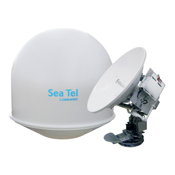
4009-9 Technical Specifications 4009-9 Installation Manual 4009-9 Technical Specifications The specifications of your antenna system are below. 20.1. Antenna Reflector/Feed 4009 The antenna assembly is comprised of the Dish, feed assembly and LNB. A variety of LNBs could be used, refer to LNB specification for the LNB that is provided with your system.: Reflector Diameter 1.0 m (40.0 inch) -
Page 110: Mk 2 Pedestal Control Unit (Pcu)
4009-9 Installation Manual 4009-9 Technical Specifications 20.4. MK 2 Pedestal Control Unit (PCU) The PCU Assembly contains 3 Printed Circuit Boards (PCBs). Connectors AC Power 100-240 VAC, 2A-1A Mini USB GPS Input RJ-11 connector Motor Control DA-15S connector 70/140 MHz SMA (on 4 ch Modem) 70/140 MHz input Rotary Joint L-Band... -
Page 111: Mh Z Base & Pedestal Unlimited Azimuth Modems (3 Channel )
4009-9 Technical Specifications 4009-9 Installation Manual 20.6. 400 MHz Base & Pedestal Unlimited Azimuth Modems (3 Channel) Combined Signals (-1,-2) Pass-Thru 950-3200 MHz RX IF, Injected 22Khz Tone DC LNB Voltage Select 400 MHz Pedestal M&C Connectors: RX IF L-Band SMA female Rotary Joint SMA female... -
Page 112: Radome Assembly , 50
0.5 G (See chart below). For Naval Engineering level information on this subject, please refer to Antenna Installation Guideline – Site Arrangement, document number 130040 available on the Sea Tel Dealer Support Site. 20.8. Radome Assembly, 50” Type... -
Page 113: Ade Pedestal Power Requirements
4009-9 Technical Specifications 4009-9 Installation Manual Cable Passage - The radome base is designed with a bottom center cable passage and Roxtec® Multidiameter® blocks for cable strain relief. Bottom center cable passage is recommended, however, a strain relief kit is provided with the system if off-center cable entry is required. -
Page 114: Mechanical Conditions
4009-9 Installation Manual 4009-9 Technical Specifications 20.10.3. Mechanical Conditions Environmental Condition Test Level Systematic Vibration Amplitude 5.0 millimeters Acceleration 2.0 G (20 m/s2) Frequency Range 1Hz-150 Hz Shock (Transient Vibration) Response Spectrum Peak Accel., m/s2 Duration, ms Number of Cycles 3 each direction Directional Changes Shock (Bump) -
Page 115: C Ables
20.12.2. Antenna L-Band IF Coax Cables (Customer Furnished) Due to the loss across the length of the RF coaxes at L-Band, Sea Tel recommends the following 50 ohm coax cable types (and their equivalent conductor size) for our standard pedestal installations. Type N... - Page 116 4009-9 Installation Manual 4009-9 Technical Specifications This Page Intentionally Left Blank 20-8...
-
Page 117: Drawings
DRAWINGS 4009-9 Installation Manual DRAWINGS The drawings listed below are provided as a part of this manual for use as a diagnostic reference. 21.1. DAC-2202 Antenna Control Unit Drawings Drawing Title 125411-1_R DAC-2202 w/ DVB Rackmount General Assembly 21-3 125411-3_R DAC-2202 w/ SCPC Rackmount General Assembly 21-5 21.2. - Page 118 4009-9 Installation Manual DRAWINGS This Page Intentionally Left Blank 21-2...
- Page 119 SINGLE LEVEL MFG BILL OF MATERIAL FIND QTY PART NO REV DESCRIPTION REFERENCE DESIGNATOR 1 EA 124265 G ENCLOSURE, 1U RACKMOUNT, DAC-2200 SER 1 EA 122300 LID, DAC-2200 SERIES ENCLOSURE 1 EA 120385-2 BRACKET, LID, ACU ASS'Y, 4-40 PEM 1 EA 122445 B1 FRONT PANEL ASS'Y, DAC-2202 1 EA 122307-1 DVB RECEIVER ASS'Y, STD ACU...
- Page 120 SINGLE LEVEL MFG BILL OF MATERIAL FIND QTY PART NO REV DESCRIPTION REFERENCE DESIGNATOR 1 EA 125193 1.16 SOFTWARE, DAC-2202 ACU, COMM_IF 1 EA 124871 6.08 SOFTWARE, DAC-2202 ACU, GP32, STD 1 EA 108929-2 D POWER CORD, 110V AC (NOT SHOWN) , 1 EA 109752-3 POWER CORD, 220V AC (NOT SHOWN) ,...
- Page 121 SINGLE LEVEL MFG BILL OF MATERIAL FIND QTY PART NO REV DESCRIPTION REFERENCE DESIGNATOR 1 EA 124265 G ENCLOSURE, 1U RACKMOUNT, DAC-2200 SER 1 EA 122300 LID, DAC-2200 SERIES ENCLOSURE 1 EA 120385-2 BRACKET, LID, ACU ASS'Y, 4-40 PEM 1 EA 122445 B1 FRONT PANEL ASS'Y, DAC-2202 1 EA 127166-1 D1 SCPC RECEIVER ASS'Y, ACU / PCU, V5...
- Page 122 SINGLE LEVEL MFG BILL OF MATERIAL FIND QTY PART NO REV DESCRIPTION REFERENCE DESIGNATOR 1 EA 125193 1.16 SOFTWARE, DAC-2202 ACU, COMM_IF 1 EA 124871 6.08 SOFTWARE, DAC-2202 ACU, GP32, STD 1 EA 108929-2 D POWER CORD, 110V AC (NOT SHOWN) , 1 EA 109752-3 POWER CORD, 220V AC (NOT SHOWN) ,...
- Page 126 SINGLE LEVEL MFG BILL OF MATERIAL FIND QTY PART NO REV DESCRIPTION REFERENCE DESIGNATOR 1 EA 139838-1 GENERAL ASS'Y, 4009-9, MK2, ADVANTECH 1 EA 129165-1 RADOME ASS'Y, GA INSTALL, 50 IN, TX/R 1 EA 131081-1 4W BUC, ADVANTECH, SME-KU3600F 1 EA 131082-1 DUAL BAND LNB, ADVANTECH, SME-VJ1 1 EA 125411-3 DAC-2202, SCPC RCVR, 9 WIRE IF...
- Page 127 Sea Tel - Strictly Confidential & Proprietary. Do Not Copy, Distribute or Disclose Without Prior 139837 Written Approval From Sea Tel. 4009 3rd ANGLE 1 OF 1 Copyright c Sea Tel, Inc 2011 - Unpublished Work FIRST USED: SHEET NUMBER PROJECTION...
- Page 128 SINGLE LEVEL MFG BILL OF MATERIAL FIND QTY PART NO REV DESCRIPTION REFERENCE DESIGNATOR 1 EA 139838-1 GENERAL ASS'Y, 4009-9, MK2, ADVANTECH 1 EA 128043-2 FEED ASS'Y, 4009, KU-BAND 1 EA 131082-1 DUAL BAND LNB, ADVANTECH, SME-VJ1 SEE SYSTEM BOM , 1 EA 131081-1 4W BUC, ADVANTECH, SME-KU3600F SEE SYSTEM BOM ,...
- Page 129 SINGLE LEVEL MFG BILL OF MATERIAL FIND QTY PART NO REV DESCRIPTION REFERENCE DESIGNATOR 1 EA 128534-4 WAVEGUIDE, WR-75, H-BEND W/ FULL FLEX 1 EA 115551-320 E4 WAVEGUIDE, WR-75, EXTENSION, 2 IN, GR 1 EA 128716-1 A1 WAVEGUIDE, WR-75, KU BAND, 4006RZA 1 EA 115477-6 WAVEGUIDE, WR-75, ROTARY JOINT, L-STY 1 EA 125411-3...
- Page 130 SINGLE LEVEL MFG BILL OF MATERIAL FIND QTY PART NO REV DESCRIPTION REFERENCE DESIGNATOR INTERFAC SYSTEM BLOCK DIAGRAM, 4009-9, MK2 PROD FAMILY EFF. DATE DRAWING SHT 3 OF 8/19/2013 NUMBER 139836-1...
- Page 133 SINGLE LEVEL MFG BILL OF MATERIAL FIND QTY PART NO REV DESCRIPTION REFERENCE DESIGNATOR 1 EA 131057-1 K1 ENCLOSURE ASS'Y, PCU, 09G2, 3 CH, 232 1 EA 123861 MOUNTING PLATE 2 EA 126288-17 UNISTRUT, 1-5/8 H-CHANNEL, 17 IN, AL 8 EA 126279-3 A4 NUT, 1 5/8 UNISTRUT, 1/4-20, W/SPRING 4 EA 124588-1021 STANDOFF, HEX, F/F, 1/4-20 X .50 OD X...
- Page 134 Sea Tel - Strictly Confidential & Proprietary. Do Not Copy, Distribute or Disclose Without Prior 133931 Written Approval From Sea Tel. 4009 3rd ANGLE 1 OF 1 Copyright c Sea Tel, Inc 2011 - Unpublished Work FIRST USED: SHEET NUMBER PROJECTION...
- Page 135 SINGLE LEVEL MFG BILL OF MATERIAL FIND QTY PART NO REV DESCRIPTION REFERENCE DESIGNATOR 1 EA 123861 MOUNTING PLATE 2 EA 126288-17 UNISTRUT, 1-5/8 H-CHANNEL, 17 IN, AL 2 EA 139899-1 BRACKET, ADVANTECH BUC, 4009-9, MK2 8 EA 126279-3 A4 NUT, 1 5/8 UNISTRUT, 1/4-20, W/SPRING 4 EA 114586-537 SCREW, HEX HD, 1/4-20 x 3/4, S.S.
- Page 136 Sea Tel - Strictly Confidential & Proprietary. Do Not Copy, Distribute or Disclose Without Prior 139841 Written Approval From Sea Tel. 4009 3rd ANGLE 1 OF 1 Copyright c Sea Tel, Inc 2011 - Unpublished Work FIRST USED: SHEET NUMBER PROJECTION...
- Page 138 Purpose. To define the installation procedure for installing strain reliefs in “smooth base” radomes. Scope. This installation procedure applies to fiberglass radomes having Sea Tel’s standard four-hole mounting pattern, and M12 mounting hardware , in the 80-180 cm (34-66 in) nominal size range, typically referred to as “smooth”...
- Page 139 Procedure, Radome Strain Relief Installation Making the holes PLANNING: Space has been allowed for up to 5 ea. strain reliefs, but, install only as many as needed. (Typically only 2-3 for TX/RX systems). Refer to Fig 2 then plan which hole positions to use. For 76-inch radomes lowest holes may be approx 1.5 inches from inside wall corner with floor (ref drawing 129416).
- Page 140 Procedure, Radome Strain Relief Installation Measure, mark and drill pilot holes CAUTION: The hole locations cannot be determined accurately from outside of the radome. Using full scale drawing 132234, provided in the strain relief kit, measure mark and drill pilot holes from the inside out, and using only light pressure, use the small drill bit, (~1/8”...
- Page 141 Procedure, Radome Strain Relief Installation Fig. 5 – Outside view. Rotate General Assembly (G.A.) Once cables have been installed, rotate General Assembly (G.A.), to ensure cables are routed properly and do not interfere with azimuth rotation. Fig. 6 – Inside view. Records.
- Page 142 Procedure, Radome Strain Relief Installation Strain relief positioning for 80-180 cm (34-66 in) smooth based radomes, (May use Sea Tel drawing 132234 as template.) Document No Page 5 of 6 131226 Rev A Form # 117140-B...
- Page 143 Procedure, Radome Strain Relief Installation Strain relief positioning for 193 cm (76-inch) radomes. (May use Sea Tel drawing 132234 as template.) Document No Page 6 of 6 131226 Rev A Form # 117140-B...
- Page 144 SINGLE LEVEL MFG BILL OF MATERIAL FIND QTY PART NO REV DESCRIPTION REFERENCE DESIGNATOR 2 EA 118169-4 A2 CONNECTOR, MODULAR PLUG, RJ45 60 IN 119678 CABLE, FLAT MODULAR LINE CORD CABLE ASS'Y, RJ-45 SERIAL, 60 IN. PROD FAMILY EFF. DATE DRAWING SHT 1 OF COMMON...
- Page 146 SINGLE LEVEL MFG BILL OF MATERIAL FIND QTY PART NO REV DESCRIPTION REFERENCE DESIGNATOR 37 IN 117950-5 CABLE, SHIELD CONTROL 9535 2 EA 121899-24 WIRE PIN TERMINAL, CRIMP, 24 AWG, LT 3 EA 112267-13 SOCKET, SNAP N CRIMP, DB, 24-20 AWG 1 EA 110935-38 K1 CONNECTOR, D-SUB, DA-15S 1 EA 112570-12...
- Page 148 SINGLE LEVEL MFG BILL OF MATERIAL FIND QTY PART NO REV DESCRIPTION REFERENCE DESIGNATOR 1 EA 112657 MACHINING, TERMINAL MOUNTING STRIP 1 EA 126865-2 G PCB ASS'Y, TERMINAL MOUNTING STRIP, 5 1 EA 112936-36 D1 CABLE ASS'Y, D-SUB, 25 PIN, 36 IN 1 EA 116669-36 B1 CABLE ASS'Y, D-SUB, 9-PIN, 36 IN.
- Page 150 SINGLE LEVEL MFG BILL OF MATERIAL FIND QTY PART NO REV DESCRIPTION REFERENCE DESIGNATOR 1 EA 112657 MACHINING, TERMINAL MOUNTING STRIP 1 EA 126865-2 G PCB ASS'Y, TERMINAL MOUNTING STRIP, 5 1 EA 112936-36 D1 CABLE ASS'Y, D-SUB, 25 PIN, 36 IN 1 EA 116669-36 B1 CABLE ASS'Y, D-SUB, 9-PIN, 36 IN.
- Page 152 SINGLE LEVEL MFG BILL OF MATERIAL FIND QTY PART NO REV DESCRIPTION REFERENCE DESIGNATOR 1 EA 116880 G PANEL MACHINING, RACK, BASE MUX 1 EA 129613-2 E1 MODEM ASS'Y, 400MHZ FSK, 3 CH, BDE, R 1 EA 116388 D BRACKET, CONNECTOR 1 EA 115492-1 C8 ADAPTER, N(F)-SMA(F), W/FLANGE 8 EA 114588-107...
Need help?
Do you have a question about the 4009-9 BROADBAND-AT-SEA and is the answer not in the manual?
Questions and answers