Table of Contents
Advertisement
Quick Links
Sea Tel, Inc.
4030 Nelson Avenue
Concord, CA 94520
Tel: (925) 798-7979
Fax: (925) 798-7986
Email: seatel@cobham.com
Web: :
www.cobham.com\seatel
December 29, 2009
INSTALLATION AND OPERATION MANUAL
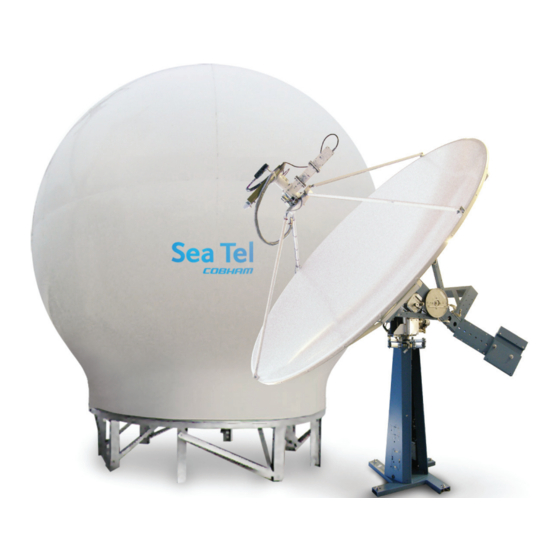
9497B-1 C/KU-BAND TVRO ANTENNA
Sea Tel Inc doing business as Cobham SATCOM
FOR SEA TEL MODEL
Sea Tel Europe
Unit 1, Orion Industrial Centre
Wide Lane, Swaythling
Southampton, UK S0 18 2HJ
Tel: 44 (0)23 80 671155
Fax: 44 (0)23 80 671166
Email: seatel@cobham.com
Web:
Document. No. 128365 Revision B
www.cobham.com\seatel
Advertisement
Table of Contents
Troubleshooting

Related Manuals for Sea Tel 9497B-1


Summary of Contents for Sea Tel 9497B-1
- Page 1 Southampton, UK S0 18 2HJ Fax: (925) 798-7986 Tel: 44 (0)23 80 671155 Email: seatel@cobham.com Fax: 44 (0)23 80 671166 Web: : www.cobham.com\seatel Email: seatel@cobham.com Web: www.cobham.com\seatel Sea Tel Inc doing business as Cobham SATCOM December 29, 2009 Document. No. 128365 Revision B...
- Page 2 All Rights Reserved. The information contained in this document is proprietary to Sea Tel, Inc.. This document may not be reproduced or distributed in any form without the consent of Sea Tel, Inc. The information in this document is subject to change without notice.
- Page 4 Revision History ECO# Date Description September 24, 2008 Initial Production Release November 3, 2008 Updated logo and font 6990 December 29, 2009 Updated with GSR2 software information...
-
Page 5: Table Of Contents
Table of Contents INTRODUCTION ......................................1-1 1.1..................................1-1 ENERAL YSTEM ESCRIPTION 1.2........................................... 1-1 URPOSE 1.3......................................1-1 YSTEM OMPONENTS 1.4..................................1-2 ENERAL SCOPE OF THIS MANUAL 1.5..................................1-2 UICK VERVIEW OF CONTENTS OPERATION ........................................2-1 2.1....................................... - Page 6 Table of Contents 4.3.4. Preparing BDE Location ................................4-2 4.3.5. Installing The System Cables ..............................4-2 4.4. ADE......................................4-2 SSEMBLING THE 4.4.1. 126” Radome, Baseframe and Antenna Pedestal System Assembly ..............4-3 4.4.2. 144” Radome, Baseframe and Antenna Pedestal System Assembly ..............4-6 4.4.3.
- Page 7 ONFIGURATION 7.5.1. To configure the PCU; ................................7-20 7.5.2. MODEL CONFIGURATION NUMBERS ..........................7-20 7.6................................... 7-20 NTENNA TOWING ROCEDURE 9497B-1 TECHNICAL SPECIFICATIONS ............................. 8-1 8.1. 9497 A ..................................... 8-1 NTENNA EFLECTOR 8.2........................................8-1 SSEMBLIES 8.2.1. TVRO-1 C/Ku Linear/Circular Feed Assembly ......................... 8-1 8.3.
- Page 8 Table of Contents 9.1..................................... 9-1 ODEL PECIFIC RAWINGS 9.2. 97B & 00B G ..............................9-1 ERIES ENERAL RAWINGS viii...
-
Page 9: Introduction
9497B-1 C/Ku-Band TVRO Introduction Introduction 1.1. General System Description Your Series 97 system is a fully stabilized antenna that has been designed and manufactured so as to be inherently reliable, easy to maintain, and simple to operate. Except for start-ups, or when changing to operate with different transponders or satellites, the equipment essentially permits unattended operation. -
Page 10: General Scope Of This Manual
1.4. General scope of this manual This manual describes the Sea Tel Series 97 Antenna (also called the Above Decks Equipment), its’ operation and installation. Refer to the manual provided with your Antenna Control Unit for its’ installation and operating instructions. -
Page 11: Operation
9497B-1 C/Ku-Band TVRO Operation Operation 2.1. System Power-up Turn the Power switch on the louvered panel of the antenna pedestal ON. This will energize the antenna pedestal and the associated RF equipment. Turn the Power switch on rear panel of the Antenna Control Unit (ACU) ON. -
Page 12: Low Noise Block Converter Operation
Operation 9497B-1 C/Ku-Band TVRO When you have a Circular feed installed, polarization adjustment. is NOT required. You should set the POL TYPE parameter in your ACU to 0000. When you have a Linear feed installed, polarization may be operated manually from the ACU but Auto-Polarization mode is the default polarization mode of operation from the ACU and is strongly recommended (set POL TYPE parameter in your ACU to 0072). -
Page 13: Basic System Information
9497B-1 C/Ku-Band TVRO Basic System Information Basic System Information This section provides you with some additional information about the satellites you will be using, basics of your Series antenna system and some of the other equipment within your system configuration. -
Page 14: Satellite Footprints
Basic System Information 9497B-1 C/Ku-Band TVRO satellite signal level required for your size of antenna (refer to the Specifications section of this manual) to provide suitable reception. This limits the number of satellites that can be used and the geographic areas where the ship can travel where the signal level is expected to be strong enough to continue providing uninterrupted reception. -
Page 15: Feed Assembly
9497B-1 C/Ku-Band TVRO Basic System Information operations of the antenna. The actual elevation pointing angle to the satellite is determined by your latitude & longitude and the longitude of the satellite. In general terms the elevation angle will be low when you are at a high latitudes and will increase as you get closer to the equator. -
Page 16: Components Of The System Configuration
Basic System Information 9497B-1 C/Ku-Band TVRO 3.3. Components of the System Configuration Figure 3-2 TVRO Simplified Block Diagram The following text provides a basic functional overview of the system components and component interconnection as referred to in the simplified block diagram for your Series antenna. Also, refer to the appropriate page of the System... -
Page 17: Antenna Ade Assembly
9497B-1 C/Ku-Band TVRO Basic System Information 3.3.1. Antenna ADE Assembly The Above Decks Equipment consists of an Antenna Pedestal inside a Radome assembly. The pedestal consists of a satellite antenna dish & feed with a linear, or a circular Low Noise Block converter (LNB) with polarization motor mounted on a stabilized antenna pedestal. -
Page 18: Above Decks Ac Power Supply
A matrix switch must be installed with all of the antenna IF coax cables connected to its’ LNB inputs. A coax cable (RG-6 OR greater) is connected from each matrix switch output to each satellite receiver. Sea Tel recommends that an ACTIVE Matrix be used in all installations. Matrix switches with 4, 8, 12 and 16 outputs are available. -
Page 19: Installation
9497B-1 C/Ku-Band TVRO Installation Installation This section contains instructions for unpacking, final assembly and installation of the equipment. It is highly recommended that final assembly and installation of the Antenna system be performed by trained technicians. Read this complete section before starting. -
Page 20: Site Survey
Installation 9497B-1 C/Ku-Band TVRO 4.2. Site Survey The radome assembly should be installed at a location aboard ship where: The antenna has a clear line-of-sight to as much of the sky (horizon to zenith at all bearings) as is practical. -
Page 21: 126" Radome, Baseframe And Antenna Pedestal System Assembly
9497B-1 C/Ku-Band TVRO Installation 4.4.1. 126” Radome, Baseframe and Antenna Pedestal System Assembly Refer to the System Block diagram, General Assembly, Radome Assembly and Base frame Assembly drawings for your system. WARNING: Assure that all nut & bolt assemblies are tightened according the tightening torque... - Page 22 Installation 9497B-1 C/Ku-Band TVRO Open each seam wide enough to install a good bead of silicone caulk, then firmly tighten all the bolts in that flange. Clean excess caulking off the inside and outside of each flange. Repeat until all flanges are sealed.
- Page 23 9497B-1 C/Ku-Band TVRO Installation 17. Fasten the antenna pedestal assembly, complete with base stand, to the base pan using the 1/2-13 x 1 1/2 (or the 3/8-16 x 1 1/2) inch bolts inserted from the bottom up and install a flat washer, a lock washer and a nut in each mounting hole.
-
Page 24: 144" Radome, Baseframe And Antenna Pedestal System Assembly
Installation 9497B-1 C/Ku-Band TVRO 21. Loosely attach the upper and lower halves of the radome using the hardware provided. Do NOT tighten the bolts at this time. 22. Insert wedges between the upper side panel assembly and the lower side panel assembly... -
Page 25: Preparing The Ade For Lift
9497B-1 C/Ku-Band TVRO Installation Set the lower half of the radome assembly on the base pan aligning the painted numbers on the radome panels. Loosely attach the lower side panel assembly to the base frame using the hardware provided. Do NOT tighten the bolts at this time. Lift the lower side panel assembly wide enough to install a good bead of silicone caulk between it and the base pan, then firmly tighten all the bolts. -
Page 26: Install Antenna/Radome/Baseframe
Sea Tel recommends that separate, dedicated, AC Power be provided for the Marine Air Conditioner (Do NOT combine with the AC Power provided for the Antenna Pedestal and RF Equipment). This AC Power cable is routed into the Marine Air Conditioner and terminated to the AC terminals inside. -
Page 27: Home Flag Position
9497B-1 C/Ku-Band TVRO Installation sequence of steps to initialize the level cage, elevation, cross-level and azimuth to predetermined starting positions. Each phase must complete properly for the antenna to operate properly (post-initialization). Refer to the initialization text in the Troubleshooting section in this manual. Observe the Initialization of the antenna pedestal. - Page 28 Installation 9497B-1 C/Ku-Band TVRO This Page Intentionally Left Blank 4-10...
-
Page 29: Setup
9497B-1 C/Ku-Band TVRO Setup Setup Below are basic steps to guide you in setting up the ACU for your specific antenna pedestal. Assure that the Antenna Pedestal (ADE) has been properly installed before proceeding. Refer to the Setup section of you ACU manual for additional parameter setting details. -
Page 30: Sat Skew Setting
Setup 9497B-1 C/Ku-Band TVRO 5.1. Sat Skew setting The Satellite Skew setting in the Satellite – Tracking Receiver sub-menu (prior to NID) is used to enter the skew of the satellite to optimize polarity angle. This feature will replace the use of POL OFFSET to optimize polarization of the feed. From here on out, POL OFFSET will serve to calibrate the feed itself. -
Page 31: To Calculate Hfo
9497B-1 C/Ku-Band TVRO Setup The Home Switch is a micro switch with a roller arm which is actuated by cam mounted on the azimuth driven sprocket, or it is a hall sensor which is actuated by a magnet mounted on the azimuth driven sprocket, which produces the “Home Flag”... -
Page 32: To Enter The Hfo Value
Setup 9497B-1 C/Ku-Band TVRO have to drive). Refer, in general terms, to the Optimizing Targeting procedure. If the antenna stopped before it got to the bow-line; When you initially target a satellite, the antenna will also stop prior to the satellite position, so you that will have to drive the Azimuth of the antenna UP to actually find the satellite. -
Page 33: Radiation Hazard And Blockage Mapping (Az Limit Parameters)
9497B-1 C/Ku-Band TVRO Setup When completed, you must save the desired HFO value. Press ENTER several times to select the REMOTE PARAMETERS display. Press the LEFT or RIGHT arrow key to enter writing mode and then press the ENTER to save the HFO value in the PCUs NVRAM. -
Page 34: Acu Factory Default Parameter Settings - Series 97B & 00B Antennas
Setup 9497B-1 C/Ku-Band TVRO 5.8. ACU Factory Default Parameter Settings – Series 97B & 00B Antennas The following table shows the factory default parameters for the ACU interfaced to a Series 97B/00B Antenna. You may need to optimize some of these parameters. Refer to the individual parameter setting information in the Setup section of your ACU manual. -
Page 35: Functional Testing
ACU / Antenna System Check Press RESET on the ACU front panel to initialize the system. Verify the display shows "SEA TEL INC - MASTER" and the ACU software version number. Wait 10 seconds for the display to change to "SEA TEL INC - REMOTE"... -
Page 36: Blockage Simulation Test
• When used as simple “BLOCKED” logic output for a single Sea Tel antenna, this output could be used to light a remote LED and/or sound a buzzer to alert someone that the antenna is blocked, and signal is lost. -
Page 37: Maintenance And Troubleshooting
Original Installation of the Series 97 system must be accomplished by or under the supervision of an authorized Sea Tel dealer for the Sea Tel Limited Warranty to be valid and in force. Should technical assistance be required to repair your system, the first contact should be to the agent/dealer you purchased the equipment from. -
Page 38: Azimuth & Elevation Drive
Maintenance and Troubleshooting 9497B-1 C/Ku-Band TVRO 7.2.4. Azimuth & Elevation Drive Refer to the Azimuth & Elevation Drive check procedure in the Functional Testing section of this manual. 7.2.5. Test Tracking Refer to the four quadrant Tracking check procedure in the Functional Testing section of this manual. -
Page 39: Series 97B-1 1C(Linear/Circular)/1Ku (Linear Only) Tvro Rf Flow
9497B-1 C/Ku-Band TVRO Maintenance and Troubleshooting air currents within the radome. These motors are also used to re-position the antenna in azimuth and elevation. The Pedestal Control Unit (PCU) uses inputs from the level cage sensors to calculate the amount of torque required in each axis to keep the antenna pointed within +/-0.2 degrees. -
Page 40: Troubleshooting Using Dacremp
7.3.4. Troubleshooting using DacRemP While troubleshooting a Sea Tel 3-Axis Antenna System, you must classify the fault you are dealing with as a failure within one of 3 major system functions, Targeting, Stabilization, and Tracking. Should there be a failure with any one of these functions, your system will not operate properly. A few simple checks may help determine which fault (if any) that you are dealing with. -
Page 41: Antenna Loop Error Monitoring
9497B-1 C/Ku-Band TVRO Maintenance and Troubleshooting Pedestal Gain Verification DISPIVC (Loop Error) Stabilization Home switch (flag) verification (Unlimited Az DISPV (Ref) Stabilization systems only) Remote Tilt Verification DISPV (Ref) Targeting Stabilization Level cage alignment Verification (sensor DISPV (Ref) Targeting alignment) -
Page 42: Reference Sensor Monitoring
Maintenance and Troubleshooting 9497B-1 C/Ku-Band TVRO • Cross-Level Axis physically moved CCW (down to the left.) and then CW (up to the right.) Elevation Axis physically moved CW. (reflector slightly pushed up) and then physically moved CCW. (reflector slightly pushed down.) At the end of chart recording shows •... - Page 43 9497B-1 C/Ku-Band TVRO Maintenance and Troubleshooting • The normal trace display for the Tilt Sensor, after performing remote tilt calibration, will be ± 4 divisions from the red reference line. Any trace line average plotted above this is of concern and troubleshooting required.
-
Page 44: Open Loop Rate Sensor Monitoring
Maintenance and Troubleshooting 9497B-1 C/Ku-Band TVRO 7.3.7. Open Loop Rate Sensor Monitoring The DacRemP DISPW graph chart provides a means for monitoring the output of the 3 solid state rate sensors (located inside the Level Cage Assembly) for diagnostic purposes. The rate sensors are the primary inputs to the PCU for stabilization. -
Page 45: Open Loop Motor Test
9497B-1 C/Ku-Band TVRO Maintenance and Troubleshooting 7.3.8. Open Loop Motor Test The DacRemP Comm Diagnostics Window provides a means to enter in Remote Commands for driving each individual torque motor to test that motors functionality. By driving each axis and observing the resulting motion of the antenna, a coarse operational status of the motor and motor driver may be established. -
Page 46: To Read/Decode An Acu Error Code 0008 (Pedestal Function Error)
Maintenance and Troubleshooting 9497B-1 C/Ku-Band TVRO input is corrupt, not stable or not consistently accurate the tracking errors will become large enough to cause the antenna to be mis-pointed off satellite. Satellite Reference Mode will uncouple the gyro reference from the azimuth rate sensor control loop. This... - Page 47 9497B-1 C/Ku-Band TVRO Maintenance and Troubleshooting Left mouse click on the icon. Right mouse click on the icon. This will display a list box with the status of the above decks pedestal filtered into 3 sections. Items preceded with a check marks indicate a flagged status.
-
Page 48: Remote Gps Lat/Lon Position
Maintenance and Troubleshooting 9497B-1 C/Ku-Band TVRO State Description PCU Status (Word 1) Slow Scan Indicates antenna is in a specialized mode, Slow Scan, which is required when ever a test requires driving the antenna >5°/sec Sat Reference Indicates that satellite reference mode is enabled. - Page 49 9497B-1 C/Ku-Band TVRO Maintenance and Troubleshooting Select the “Comm Diagnostics” window under to the Tools submenu or Press “CTRL + C” Left mouse click on the icon. Left Mouse click on the “?@ PCU GPS position, 1 min (1 Nm)”...
-
Page 50: Maintenance
Furuno default value is in Japan at 34.4N 135.2E (@3444,N,13521,E,,_). After acquiring a good fix at Sea Tel the string is @3800,N,12202,W,A^ for our 38N 122W Latitude and Longitude position. The status character tells you the status of the GPS. -
Page 51: Linear/Circular Mode Selection Verification And Alignment
9497B-1 C/Ku-Band TVRO Maintenance and Troubleshooting one location on the equipment frame to the same location on the opposite side of the equipment frame (ie from the top left of the reflector mounting frame to the top right of the reflector mounting frame). - Page 52 Maintenance and Troubleshooting 9497B-1 C/Ku-Band TVRO POL Pot Calibration Loosen the screw that secures the POL Pot mounting plate to the feed Scalar plate. Slide mounting plate out until the POL Pot sprocket is no longer engaged with the OMT sprocket.
-
Page 53: To Adjust Tilt
9497B-1 C/Ku-Band TVRO Maintenance and Troubleshooting Enter in the 5V OFFSET and the 5V SCALE parameters found in the SETUP menu. 5V OFFSET=CCW value ( recorded in step 2 – 5V SCALE=Center value ( 5V OFFSET recorded in step 3) - Page 54 Maintenance and Troubleshooting 9497B-1 C/Ku-Band TVRO either the ACU front panel or DacRemP diagnostic software by connecting the ACU’s RS-422 M&C Port to an available serial port on a Laptop/Desktop computer using a standard 9 pin serial cable. Step 1 Turn Off DishScan Drive.
-
Page 55: 7.4.4. To Reset/Reinitialize The Antenna
9497B-1 C/Ku-Band TVRO Maintenance and Troubleshooting From antenna: Observe the bubble for approximately 3-5 minutes to ensure it remains centered. Using DacRemP: Select the reference sensor graph. Verify the CL and LV displays are steady and within 4 divisions of nominal. (Anything more... -
Page 56: Pedestal Control Unit Configuration ( Xx 97B
Maintenance and Troubleshooting 9497B-1 C/Ku-Band TVRO 7.5. Pedestal Control Unit Configuration (xx97B & xx00) The PCU is designed to be used with a variety of antenna pedestal configurations. The configuration information that is unique to each pedestal type is stored in a Non Volatile Random Access Memory (NVRAM) in the PCU enclosure. If the PCU is replaced or the NVRAM in the PCU should become corrupt, the PCU must be re-configured to operate with the pedestal it is installed on. - Page 57 Maintenance and Troubleshooting The normal operating condition for the Sea Tel Antenna system is to remain powered up at all times. This ensures that the antenna remains actively stabilized to prevent physical damage to the antenna pedestal and reduce condensation and moisture in the radome to prevent corrosion.
- Page 58 Maintenance and Troubleshooting 9497B-1 C/Ku-Band TVRO This Page Intentionally Left Blank 7-22...
-
Page 59: 9497B-1 Technical Specifications
9497B-1 C/Ku-Band TVRO 9497B-1 Technical Specifications 9497B-1 Technical Specifications The technical specifications for your Series Above Decks Equipment subsystems are listed below: Refer to your ACU manual for its’ Specifications. 8.1. 9497 Antenna Reflector Type Hydro Formed Aluminum Parabola Diameter (D) 2.4 Meter (94 inches) -
Page 60: Stabilized Antenna Pedestal Assembly
9497B-1 Technical Specifications 9497B-1 C/Ku-Band TVRO 8.3. Stabilized Antenna Pedestal Assembly Type: Three-axis (Level, Cross Level and Azimuth) Stabilization: Torque Mode Servo Stab Accuracy: 0.3 degrees MAX, 0.15 degrees RMS in presence of specified ship motions (see below). LV & CL motors: Size 34 Brushless DC Servo motor with integrated brake. -
Page 61: 126" Radome Assembly
Withstand relative average winds up to 100 MPH from any direction. Ingress Protection Rating All Sea Tel radomes have an IP rating of 56 NOTE: Radome panels can absorb up to 50% moisture by weight. Soaked panels will also have higher attenuation. -
Page 62: Environmental Conditions (Ade)
2, 4 or 6 cables are required dependant upon which feed/LNB configuration your antenna is fitted with. Due to the dB losses across the length of the RF coaxes at L-Band, Sea Tel recommends the following 75 ohm coax cable types (and their equivalent conductor size) for our standard pedestal installations:... -
Page 63: Ac Power Cable Above Decks (Customer Furnished)
9497B-1 C/Ku-Band TVRO 9497B-1 Technical Specifications 8.7.3. AC Power Cable Above Decks (Customer Furnished) Voltage: 110 or 220 volts AC, 50/60 Hz., single phase 100 Watts MAX, pedestal only Power: 8.7.4. Gyro Compass Interface Cable (Customer Furnished) Type: Multi-conductor, Shielded... - Page 64 9497B-1 Technical Specifications 9497B-1 C/Ku-Band TVRO This Page Intentionally Left Blank...
-
Page 65: Model 9497B-1 Drawings
System, Model 9497B-1, 126” Radome 128354-1_A1 System, Model 9497B-1, 144” Radome 128357-2_B System Block Diagram – Model 9497B-1 128265-3_B1 General Assembly – Model 9497B-1 & -2 9-10 128358_A Antenna System Schematic – Model 9497B-1 9-12 128269-2_C Antenna Assembly, 2.4M, Dual C/Quad Ku... - Page 66 Model 9497B-1 Drawings 9497B-1 C/Ku-Band TVRO This Page Intentionally Left Blank...
- Page 67 FIND QTY PART NO REV DESCRIPTION REFERENCE DESIGNATOR 1 EA 128265-3 B1 GENERAL ASS'Y, 9497B-1 & -2, TVRO 1 EA 111678-9 K2 RADOME ASS'Y, 126 INCH, WHITE/SIDE AC 1 EA 123723-1 B1 RADOME BASE ASS'Y, 75 IN., STL, NO AC...
- Page 69 SINGLE LEVEL MFG BILL OF MATERIAL FIND PART NO DESCRIPTION REFERENCE DESIGNATOR 128265-3 GENERAL ASS'Y, 9497B-1 & -2, TVRO 111365-17 RADOME ASS'Y, 144 INCH, WHITE/SIDE A 123723-1 RADOME BASE ASS'Y, 75 IN., STL, NO AC, 128269-2 ANTENNA ASS'Y, 9497B-1 TVRO...
- Page 71 SINGLE LEVEL MFG BILL OF MATERIAL FIND QTY PART NO REV DESCRIPTION REFERENCE DESIGNATOR 1 EA 128265-3 B1 GENERAL ASS'Y, 9497B-1 & -2, TVRO 1 EA 128269-2 ANTENNA ASS'Y, 9497B-1 TVRO 1 EA 123649 A1 FEED ASS'Y, C/KU, TVRO DISHSCAN 1 EA 113770-2...
- Page 72 1 EA 128253-6 X2 HARNESS ASS'Y, 4 CH, RG-59, F(M) TO F 1 EA 111115-6 CABLE ASS'Y, F(M)-F(M), 6 FT. 4 EA 109391 ADAPTER, F(F)-F(F) (BULLET), 0.84 IN SYSTEM BLOCK DIAGRAM, 9497B-1 PROD FAMILY EFF. DATE DRAWING SHT 2 OF 12/29/2009...
- Page 74 B1 ELECT. EQ. FRAME, XX97B-1 & -2, TVRO 1 EA 121655-1 LABELS INSTALLATION 1 EA 123530-4 GROUND BONDING KIT, XX97, TVRO (NOT SHOWN) GENERAL ASS'Y, 9497B-1 & -2, TVRO PROD FAMILY EFF. DATE DRAWING SHT 1 OF 97 TVRO 12/29/2009...
- Page 77 WASHER, FLAT, 1/4, S.S. 4 EA 114586-623 SCREW, HEX HD, 3/8-16 x 1, S.S. 8 EA 114580-031 WASHER, FLAT, 3/8, S.S. 4 EA 114583-031 NUT, HEX, 3/8-16, S.S. ANTENNA ASS'Y, 9497B-1 TVRO PROD FAMILY EFF. DATE DRAWING SHT 1 OF COMMON 12/29/2009...
- Page 79 SINGLE LEVEL MFG BILL OF MATERIAL FIND PART NO DESCRIPTION REFERENCE DESIGNATOR 123648-1 SCALAR PLATE ASS'Y, C/KU-BAND, RX ON 116286-4 OMT, DUAL BAND, 2-PORT 110256-2 WAVEGUIDE FILTER, WR-229, 3.7-4.2GHz 114540 LNB, C-BAND 113770-2 LNB, KU-WIDEBAND 112729 BRACKET, FEED COUNTERWEIGHT 119820-113 SCREW, HEX HD, M4 X 12 S.S.
- Page 81 SINGLE LEVEL MFG BILL OF MATERIAL FIND PART NO DESCRIPTION REFERENCE DESIGNATOR NOT SHOWN 113741 HARDWARE KIT, 126 INCH RADOME NOT SHOWN 117762-1 SILICONE ADHESIVE, WHT RTV 122, 10.1 115931-9 RADOME FAB ASS'Y, 126 INCH, WHITE/FO 124903-1 STRAIN RELIEF ASS'Y 114586-538 SCREW, HEX HD, 1/4-20 x 1, S.S.
- Page 83 SINGLE LEVEL MFG BILL OF MATERIAL FIND PART NO DESCRIPTION REFERENCE DESIGNATOR NOT SHOWN 117762-1 SILICONE ADHESIVE, WHT RTV 122, 10.1 NOT SHOWN 110327 HARDWARE KIT, 144 INCH RADOME 109119-17 RADOME FAB ASS'Y, 144 INCH, WHITE/SID 124903-1 STRAIN RELIEF ASS'Y INCLUDED IN HARDWARE KIT 114586-538 SCREW, HEX HD, 1/4-20 x 1, S.S.
- Page 85 SINGLE LEVEL MFG BILL OF MATERIAL FIND PART NO DESCRIPTION REFERENCE DESIGNATOR 123724-1 RADOME BASE FRAME ASS'Y, 75 IN, STEE 123726-1 RADOME BASE PAN FAB, WHITE 123728-2 RADOME PAN ACCESS ASS'Y, WHITE 114586-540 SCREW, HEX HD, 1/4-20 x 1-1/4, S.S. 114580-029 WASHER, FLAT, 1/4, S.S.
- Page 86 NOTES: (UNLESS OTHERWISE SPECIFIED) 1-14-05 RELEASED TO PRODUCTION NONE 04-13-05 -9 ADDED 1. APPLY ADHESIVE PER SEA TEL SPEC. 121730. NONE 04-29-05 -9 BASE FRAME WS STL. LG. FOOT, BASE PAN WS P/N 123726-2 4888 05-31-05 FOR -5, -6, -8, -9 BASE PAN WAS P/N 123726-1.
- Page 89 SINGLE LEVEL MFG BILL OF MATERIAL FIND PART NO DESCRIPTION REFERENCE DESIGNATOR 123907-14569 BELT, TIMING, 1/5 PITCH, 145 GROOVES, 1 123907-17269 BELT, TIMING, 1/5 PITCH, 172 GROOVES, 1 116430-17525 BELT, TIMING, .080 PITCH, 175 GROOVES, BELT KIT, XX97B / XX00B PROD FAMILY EFF.
- Page 90 SINGLE LEVEL MFG BILL OF MATERIAL FIND PART NO DESCRIPTION REFERENCE DESIGNATOR 127903-1 EL MOTOR ASS'Y, WITH BRAKE, 9797B-76 127901-1 MOTOR ASS'Y, CROSS LEVEL, 9797B-76 125081-2 AZ TRAIN MOTOR ASS'Y, XX07, LH TERMI 122532-1 SHIELDED LEVEL CAGE MOTOR ASS'Y, .0 121880-1 MOTOR ASS'Y, POLANG, (PRI-FOCUS) 116463...
- Page 91 SINGLE LEVEL MFG BILL OF MATERIAL FIND PART NO DESCRIPTION REFERENCE DESIGNATOR 127513-1 PCU ASS'Y, XX97B, STD 117168-1 MODEM ASS'Y, PEDESTAL, 3 CH, 75 OHM 117168-2 MODEM ASS'Y, BASE, 3 CH, 75 OHM 122208-1 LEVEL CAGE ASS'Y, 90 DEG EL RANGE, IN 116024-3 SHIELDED POLANG RELAY ASS'Y 127602-2...
- Page 93 SINGLE LEVEL MFG BILL OF MATERIAL FIND PART NO DESCRIPTION REFERENCE DESIGNATOR 116880 PANEL MACHINING, RACK, BASE MUX 117168-2 MODEM ASS'Y, BASE, 3 CH, 75 OHM 118429 BRACKET, CONNECTOR 128001-8BLU CABLE ASS'Y, RG-179 COAX, F(M) TO SMA 114178 ADAPTER, F(F)-F(F) (BULLET), 1.0 IN L 114588-144 SCREW, PAN HD, PHIL, 6-32 x 1/4, S.S.
- Page 94 RELEASED TO PRODUCTION; WAS REV X2 NOTES: UNLESS OTHERWISE SPECIFIED APPLY ADHESIVE PER SEATEL SPEC. 121730. TORQUE THREADED FASTENERS PER SEATEL SPEC. 122305. IDENTIFY PER SEA TEL SPEC. 122930, APPROX. WHERE SHOWN. DRAWN BY: UNLESS OTHERWISE SPECIFIED DIMENSIONS ARE IN INCHES.
Need help?
Do you have a question about the 9497B-1 and is the answer not in the manual?
Questions and answers