Table of Contents
Advertisement
Quick Links
Sea Tel, Inc.
4030 Nelson Avenue
Concord, CA 94520
Tel: (925) 798-7979
Fax: (925) 798-7986
Email: seatel@seatel.com
Web:
www.seatel.com
September 26, 2007
INSTALLATION AND MAINTENANCE MANUAL
FOR SEA TEL MODEL
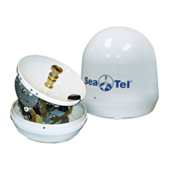
COASTAL 14 SATELLITE TV RECEIVE-ONLY ANTENNA
Look to the Leader. Look to Sea Tel.
Sea Tel Europe
Unit 1, Orion Industrial Centre
Wide Lane, Swaythling
Southampton, UK S0 18 2HJ
Tel: 44 (0)23 80 671155
Fax: 44 (0)23 80 671166
Email: europe@seatel.com
Web:
www.seatel.com
Document. No. 126352
Revision B
Advertisement
Table of Contents

Subscribe to Our Youtube Channel
Related Manuals for Sea Tel Coastal 14


Summary of Contents for Sea Tel Coastal 14
- Page 1 Southampton, UK S0 18 2HJ Fax: (925) 798-7986 Tel: 44 (0)23 80 671155 Email: seatel@seatel.com Fax: 44 (0)23 80 671166 Web: www.seatel.com Email: europe@seatel.com Look to the Leader. Look to Sea Tel. Web: www.seatel.com September 26, 2007 Document. No. 126352 Revision B...
- Page 2 All Rights Reserved. The information contained in this document is proprietary to Sea Tel, Inc.. This document may not be reproduced or distributed in any form without the consent of Sea Tel, Inc. The information in this document is subject to change without notice.
-
Page 3: Table Of Contents
AINTENANCE 3.4. F ................... 3-2 AULT SOLATION ROUBLE SHOOTING 3.5. R LNB......................3-3 EPLACING A EFECTIVE 4. COASTAL 14 TECHNICAL SPECIFICATIONS................... 4-1 4.1. I ........................4-1 NSTALLED EIGHT 4.2. R ............................4-1 ADOME 4.3. A ............................. 4-1 NTENNA 4.4. S ........................ - Page 4 Table of Contents 4.8. E .......................... 4-3 NVIRONMENTAL 5. COMPUTER INTERFACE ........................5-4 5.1. C ......................5-4 ONNECTING THE COMPUTER 6. DRAWINGS............................6-7 6.1. C 14 D ........................ 6-7 OASTAL RAWINGS...
-
Page 5: Installation
Installation of your Coastal Series Antenna system must be accomplished by or under the supervision of an authorized Sea Tel dealer for the Sea Tel Limited Warranty to be valid and in force. Good planning of the installation will provide the best results. Below is some guidance on issues that are important to consider when planning the installation. -
Page 6: Coastal 14 System Inventory
1.2. Coastal 14 System Inventory Please inventory the contents of the box. It should contain all items listed in the Coastal 14 Packing List Document number 126370 found in the back of this manual. 1.3. -
Page 7: Prepare The Satellite Receiver And Television Mounting Locations
Coastal 14 Ku-Band TVRO Installation 1.6. Prepare the Satellite Receiver and Television mounting locations Prepare the mounting locations for the satellite receiver and television set ( or monitor and stereo sound system). 1.7. Running the Cables 1.7.1. Antenna Cable Route the “F” connector end of the antenna cable down from the radome mounting location through the boat to the antenna control panel location. - Page 8 Installation Coastal 14 Ku-Band TVRO 2. Remove the radome top by removing the three screws that thread into the radome base. 3. Set the radome top aside in a safe location until you are ready to close the radome. 4. Cut the shipping tie-wraps to allow free movement of the antenna mechanism.
-
Page 9: Install The Antenna Control Panel
Coastal 14 Ku-Band TVRO Installation 7. Lift the base of the radome up and connect the antenna cable to the base of the antenna. 8. While being careful not to pinch or kink the antenna cable, set the radome base mounting bolts into the mounting holes. -
Page 10: Install The Satellite Receiver And Television Set
Installation Coastal 14 Ku-Band TVRO 4. Connect the antenna cable to the IN connector of the antenna control panel. This IN connection supplies 30VDC operating voltage and antenna control signals to the antenna and receives satellite signal from the antenna. -
Page 11: Setup
Coastal 14 Ku-Band TVRO Setup Setup 2.1. System Checkout 1. Press the ON key on the antenna control panel. Both LED’s (TRACKING and UNWRAP) should illuminate for 5 seconds verifying the DC power and LED cable connections between the antenna control panel and the antenna pedestal assembly. -
Page 12: Setting Auto Threshold For Proper Tracking
Setup Coastal 14 Ku-Band TVRO 2.3.2. Setting Auto Threshold for Proper Tracking Auto Threshold needs to be set to about 1/3 of the difference in AGC between noise floor (OFF satellite) signal level and peak (ON satellite) signal level. The most common value for the Coastal 14 is 60. - Page 13 Coastal 14 Ku-Band TVRO Setup 2.3.3.2. NAME Enter or edit the 6 character Name you want to use for this saved satellite. 1. Press the NEXT key to SELECT this sub-menu parameter for adjustment. 2. A cursor will appear under the leftmost character. Press ▼ & ▲ arrow keys to increment/decrement this character.
- Page 14 Setup Coastal 14 Ku-Band TVRO 4. Continue editing until all 4 digits have been set to the desired tracking Frequency for this satellite selection. Press the SAVE key to save the FREQ parameter for this SAT. 5. If you want to edit any of the other default values that are loaded with preset, press the ▼...
- Page 15 Coastal 14 Ku-Band TVRO Setup 2.3.3.7. Enter or edit the best Forward Error Correction rate for the receiver to use for this satellite. This choice presets all of the other sub-menu parameters to factory defaults for the satellite you choose to set this SAT to.
-
Page 16: Sat2 - Second Satellite Parameters
Setup Coastal 14 Ku-Band TVRO 3. Press the NEXT key to move the cursor to the digit to the left. Press ▼ & ▲ arrow keys to increment/decrement this digit. 4. Continue editing until all 4 digits have been set to the desired NID for this satellite selection. -
Page 17: Sat6 - Sixth Satellite Parameters
Accessing the Factory Settings parameters should ONLY be done by a qualified technician from an authorized Sea Tel dealer. The Model Serial Number can be found on the blue and silver label below the reflector, on the blue frame of the pedestal. The parameters are: 2.3.9.1. - Page 18 24 inch diameter reflector 30 inch diameter reflector 3. When the correct model value (Coastal 14) is displayed, press the SAVE key to save the Model Number parameters. This saves the drive, scale factors and limits for this antenna. If this parameter is NOT set correctly, the antenna WILL malfunction.
-
Page 19: Saving The Setup Parameters
Coastal 14 Ku-Band TVRO Setup 5. Press the NEXT key to move the cursor to the next character to the right. Press ▼ & ▲ arrow keys to toggle this character between E (East) and W (West). 6. Press the SAVE key to save the current ships longitude in the LON parameter. - Page 20 Setup Coastal 14 Ku-Band TVRO This Page Intentionally Left Blank 2-10...
-
Page 21: Maintenance
Original Installation of the Coastal Series system must be accomplished by or under the supervision of an authorized Sea Tel dealer for the Sea Tel Limited Warranty to be valid and in force. -
Page 22: Preventive Maintenance
Maintenance Coastal 14 Ku-Band TVRO 3.3. Preventive Maintenance As needed - Clean the outside surface of the radome with warm soapy water to remove dust, grime and salt residue. There is no other preventive maintenance required 3.4. Fault Isolation/Trouble-shooting The following table is provided to help isolate problems in the Coastal Series Antenna system. -
Page 23: Replacing A Defective Lnb
Coastal 14 Ku-Band TVRO Maintenance Antenna tracks well at the pier, but 1. Call dealer/agent for further assistance loses the satellite when underway Antenna does not stay on satellite 1. Check all coax cables for poor connection at pier, or underway 2. - Page 24 Maintenance Coastal 14 Ku-Band TVRO This Page Intentionally Left Blank...
-
Page 25: Coastal 14 Technical Specifications
Mounting 4 x ¼-20 fasteners Wind: Withstand relative average winds up to 100 MPH from any direction. Ingress Protection Rating All Sea Tel radomes have an IP rating of 56 4.3. Antenna Type Spun Aluminum reflector Size 14.5 inch (36.8cm) -
Page 26: Us Circular Lnb
Coastal 14 Technical Specifications Coastal 14 Ku-Band TVRO Elevation Pointing +/- 15 degrees of Roll 35 to 60 degrees +/- 25 degrees of Roll 40 to 50 degrees 4.5. US Circular LNB Sea Tel Part Number: 115075-1 Type: Single output... -
Page 27: Environmental
Coastal 14 Ku-Band TVRO Coastal 14 Technical Specifications 4.8. Environmental Temperature -20 to +55 degrees C. Humidity Up to l00% @ 40 degrees C. Rain Up to 4 inches per hour. Degraded RF performance when the radome surface is wet. -
Page 28: Computer Interface
Computer Interface Coastal 14 Ku-Band TVRO Computer Interface A computer can be connected to the antenna control panel to allow you to provide access to ALL the parameter settings of the query the Coastal Series antenna and view the responses it provides. The commands to set the parameters in the Coastal Series PCU are summarized below. - Page 29 Coastal 14 Ku-Band TVRO Computer Interface Check “Send line ends with line feeds”, “Echo typed characters locally” and “Append line feeds to incoming line ends”. Click OK. Type ^0086 and hit ENTER. Refer to the command information below to communicate with the antenna system. The Display Antenna Control Panel will be locked while you are connected to the computer.
- Page 30 Computer Interface Coastal 14 Ku-Band TVRO This Page Intentionally Left Blank...
-
Page 31: Drawings
Coastal 14 Ku-Band TVRO Drawings The following drawings are included with this manual for installation and maintenance reference. 6.1. Coastal 14 Drawings Drawing Title 125818_D System, Coastal 14 125699-1_C System Block Diagram 6-11 126340_A1 Antenna Schematic 6-13 125773_E General Assembly... - Page 32 Drawings Coastal 14 Ku-Band TVRO This page left blank intentionally...
- Page 33 CABLE ASS'Y, RF, RG6, 50 FT. 111115-6 CABLE ASS'Y, F(M)-F(M), 6 FT. (NOT SHOWN) 126305 HARNESS ASS'Y, DC POWER, COASTAL 1 (NOT SHOWN) 126372 CUSTOMER DOC PACKET, COASTAL 14 110567-11 ADAPTER, N(M)-F(F), STRAIGHT (NOT SHOWN) 126370 PACKING LIST, COASTAL 14 (NOT SHOWN) 126594-1...
- Page 34 CABLE ASS'Y, P/N: 125964-10 AND SMB CONNECTOR, P/N:125763-1 BEFORE INSTALLING CABLE. REFERENCE CABLE ASS'Y 125964-10 IN GENERAL ASS'Y 125773. REFERENCE DRAWINGS: 125699 SYSTEM BLOCK DIAGRAM, COASTAL 14 126340 SCHEMATIC, ANTENNA, COASTAL 14 DRAWN BY: UNLESS OTHERWISE SPECIFIED DIMENSIONS ARE IN INCHES.
- Page 35 PART NO DESCRIPTION REFERENCE DESIGNATOR 125773 GENERAL ASS'Y, COASTAL 14 125822 RADOME ASS'Y, COASTAL 14 125824 FEED, 14" ANTENNA, COASTAL 14 115075-1 LNB MOD, DUAL, US 123092 CONVERTER, HDTV 110 WEST 121966-2 GPS ANTENNA, RETERMINATED, 21.0 L 126068-1 PCU ENCLOSURE ASS'Y, 2-AXIS, COASTA...
- Page 38 125817 ANTENNA ASS'Y, COASTAL 14 125816 PEDESTAL ASS'Y, COASTAL 14 126068-1 PCU ENCLOSURE ASS'Y, 2-AXIS, COASTA 126403-1 COVER, PCU ENCLOSURE, COASTAL 14 126083 FSK ENCLOSURE ASS'Y, ADE, COASTAL 1 123092 CONVERTER, HDTV 110 WEST 121966-2 GPS ANTENNA, RETERMINATED, 21.0 L...
- Page 39 114588-196 SCREW, PAN HD, PHIL, 8-32 x 5/8, S.S. 119952-011 WASHER, STAR, INTERNAL TOOTH, #10, S 119952-007 WASHER, STAR, INTERNAL TOOTH, #6, S. GENERAL ASS'Y, COASTAL 14 PROD FAMILY EFF. DATE DRAWING NUMBER SHT 2 OF 2 SERIES 98 25-Sep-07...
- Page 40 Tel. 925-798-7979 Fax. 925-798-7986 X.XXX = .005 APPROVED BY: TITLE: ANGLES: .5 GENERAL ASSEMBLY INTERPRET TOLERANCING PER ASME Y14.5M - 1994 MATERIAL: APPROVED DATE: COASTAL 14 FINISH: SIZE SCALE: DRAWING NUMBER 125773 COASTAL 14 3rd ANGLE 1 OF 1 FIRST USED:...
- Page 41 SINGLE LEVEL MFG BILL OF MATERIAL FIND PART NO DESCRIPTION REFERENCE DESIGNATOR 125686 REFLECTOR, 14.5 INCH MACHINING 125824 FEED, 14" ANTENNA, COASTAL 14 123745 MOUNTING CUFF, LNB 115075-1 LNB MOD, DUAL, US 114593-104 SCREW, SOCKET HD, 4-40 x 3/8, S.S. 114587-148 SCREW, RND HD, PHIL, 6-32X 1/2, S.S...
- Page 42 Tel. 925-798-7979 Fax. 925-798-7986 X.XXX = .005 APPROVED BY: TITLE: ANGLES: .5 ANTENNA ASSEMBLY INTERPRET TOLERANCING PER ASME Y14.5M - 1994 MATERIAL: APPROVED DATE: COASTAL 14 FINISH: SIZE SCALE: DRAWING NUMBER 125817 COASTAL 14 3rd ANGLE 1 OF 1 FIRST USED:...
- Page 43 125697 RADOME TOP FAB, 16 IN 125763-1 ADAPTER, SMB (M) TO N (F), 75 OHM, BUL 110481-5 DECAL, LOGO, SEA TEL, 11.4 X 4 IN 127134-3 GASKET, FOAM RUBBER, 3" DIA. 114576-197 SCREW, FLAT HD, PHIL, 8-32 x 3/4, S.S.
- Page 44 Tel. 925-798-7979 Fax. 925-798-7986 X.XXX = .005 APPROVED BY: TITLE: ANGLES: .5 RADOME ASSEMBLY INTERPRET TOLERANCING PER ASME Y14.5M - 1994 STAR WASHER MATERIAL: APPROVED DATE: COASTAL 14 FOR ITEM #3 FINISH: SIZE SCALE: DRAWING NUMBER NUT FOR 125822 ITEM #3 3rd ANGLE...
- Page 45 4X 1/4 FLAT WASHER ANGLES: INSTALLATION ARRANGEMENT INTERPRET TOLERANCING PER ASME Y14.5M - 1994 4X 1/4 SMALL PATTERN FLAT WASHER MATERIAL: APPROVED DATE: COASTAL 14 4X 1/4-20 NUT, NYLON INSERT 4X 1/4-20 X 2-1/2 HEX HEAD SCREW FINISH: SIZE SCALE: DRAWING NUMBER...
- Page 46 Please inventory the contents of the box. It should contain: Checked Coastal 14 This is comprised of a 125773 GENERAL ASS'Y, COASTAL Antenna 14 inside a 125822 RADOME ASS'Y, COASTAL 14. Radome assembly SN: ____________________ 113480-1 Antenna Cable Assembly, RG-6, F(M) TO F(M), 50 FT...
- Page 47 126350 Manuals CD, Coastal 14 121879 Warranty Packet Checked By: __________ Date: __________ Packaged By: __________ Date: __________ Document No Page 2 of 2 126370 D...
Need help?
Do you have a question about the Coastal 14 and is the answer not in the manual?
Questions and answers